FINAL PROJECT
VIDEO
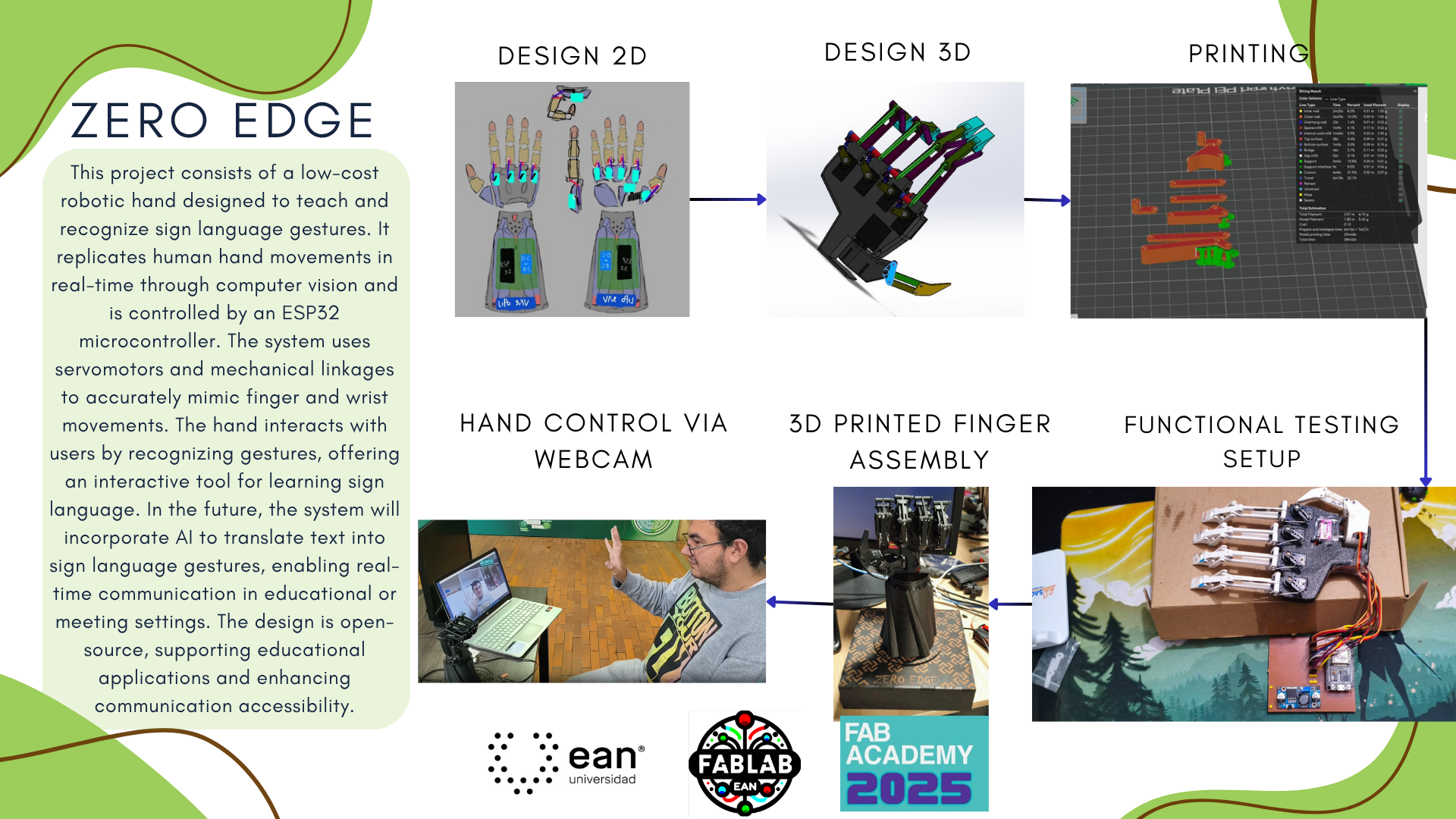
ZERO EDGE
Project Timeline (FabAcademy 2025)
Phase 1: Idea & Planning (April 15 – April 30, 2025)
- Define the social problem and technical solution (focus on helping teach sign language).
- Research on four-bar mechanisms and vision-based control.
- Early sketches and system architecture design.
- Component selection and system overview.
Phase 2: Early Prototyping (May 1 – May 10, 2025)
- CAD modeling of the robotic hand and finger joints.
- Develop basic vision system in Python using OpenCV.
- Initial testing of gesture detection and servo control.
Phase 3: Mechanical Fabrication (May 11 – May 17, 2025)
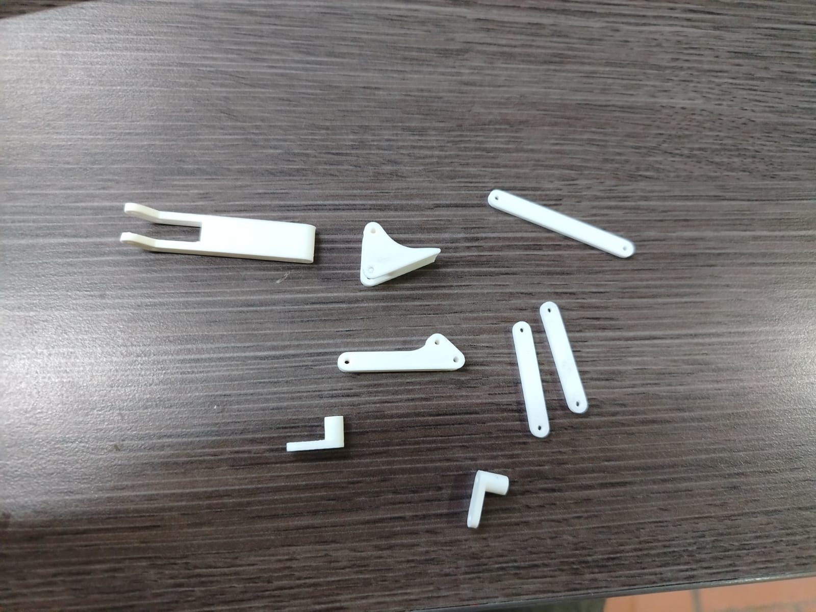
- 3D printing of the prosthetic structure and finger links.
- Assembly of four-bar mechanisms for each finger.
- Servo placement and mechanical motion verification.
Phase 4: Electronics & PCB Manufacturing (May 18 – May 24, 2025)
- Design and routing of the custom PCB.
- Milling and soldering of the board.
- Wiring of the system: ESP32, servos, power supply, and PCB.
Phase 5: System Integration (May 25 – May 31, 2025)
- Final assembly of all components.
- Communication between ESP32 and servos via GPIO/PWM.
- Full integration of the vision system with motor control.
Phase 6: Testing & Documentation (June 1 – June 7, 2025)
- Motion calibration and tuning.
- System validation with multiple gesture inputs (for sign language).
- Final documentation: BOM, source code, design files, images, and videos. Upload to the FabAcademy project page.
Project Idea Sketch
What is Zero Edge?
Zero Edge is a robotic prosthetic hand designed to teach and recognize sign language gestures. The project aims to provide an accessible and interactive tool for learning sign language by mimicking human hand movements. In the future, the system will incorporate artificial intelligence to translate sign language into spoken language, facilitating communication between individuals using sign language and those unfamiliar with it.
Key Features of Zero Edge
- Artificial Vision Control: Hand gestures are detected in real time using a USB camera, interpreted by the ESP32 using OpenCV.
- ESP32 as Core Processor: Handles image processing and gesture recognition, triggering servo actuation.
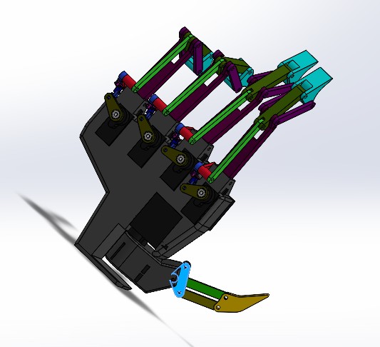
- Four-Bar Mechanisms: Each finger uses a mechanical system designed to replicate realistic finger articulation with efficiency and strength.
- Custom PCB: Built to streamline power distribution and simplify wiring between components.
- 3D Printed Structure: Lightweight, ergonomic design printed using PLA or PETG for durability.
- Two LiPo Batteries (3.7V): Ensures consistent energy to all servos and electronics.
- Real-time Movement Replication: Vision-based gesture input from the user is reflected immediately in the prosthetic movement.
- Open-source Architecture: All design files, code, and diagrams will be shared to promote accessibility and collaboration.
Future Enhancement: AI Integration
The long-term goal of Zero Edge is to integrate an AI system that translates sign language gestures into spoken language. This AI would analyze the movements made by the robotic hand and generate real-time verbal communication. This feature will allow individuals to communicate with a broader audience, making sign language more accessible.
Where will they come from?
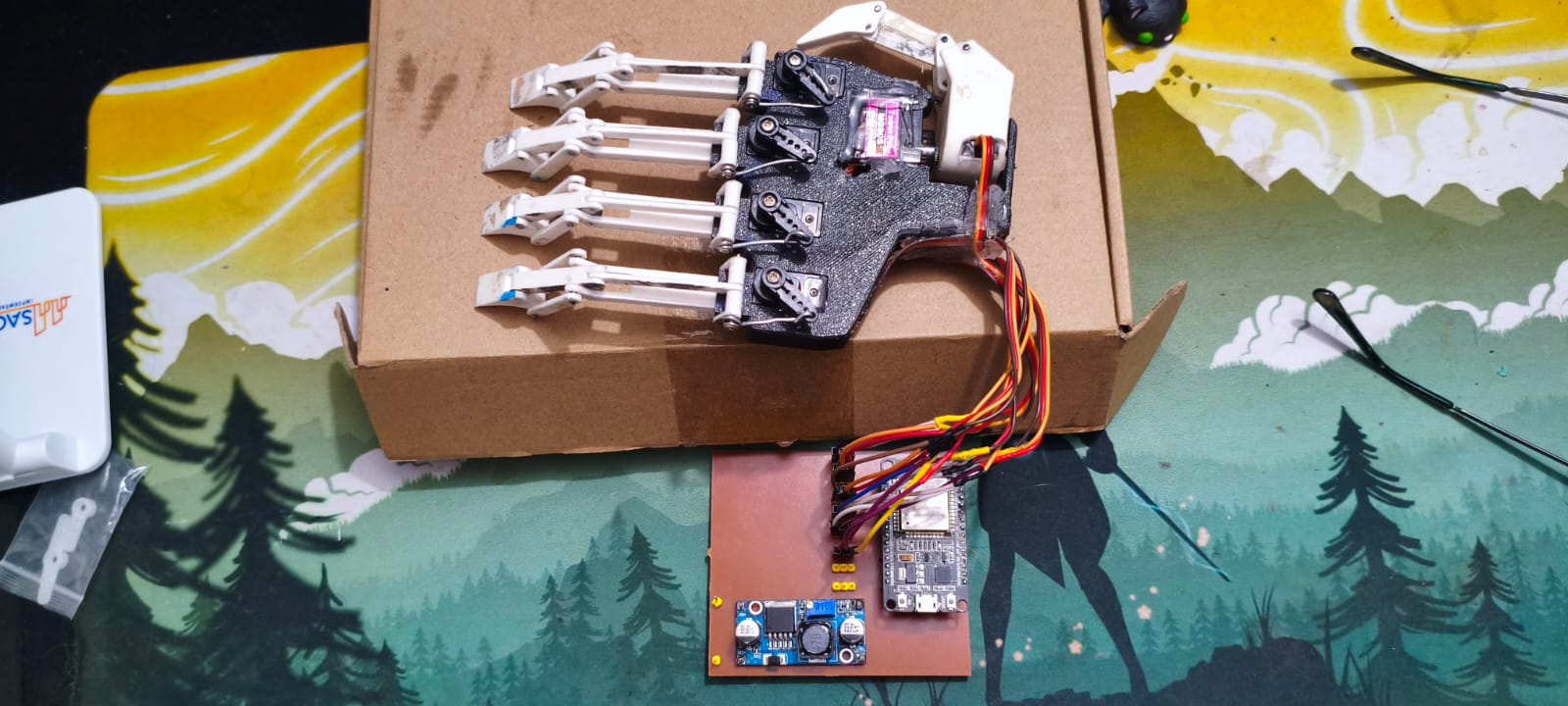
For the construction of my robotic hand, I used a combination of 3D printed parts and electronic components. The structural parts of the fingers and the palm were designed in CAD and printed using PLA PRO filament, which is known for its strength and precision. This filament was purchased specifically for the project.

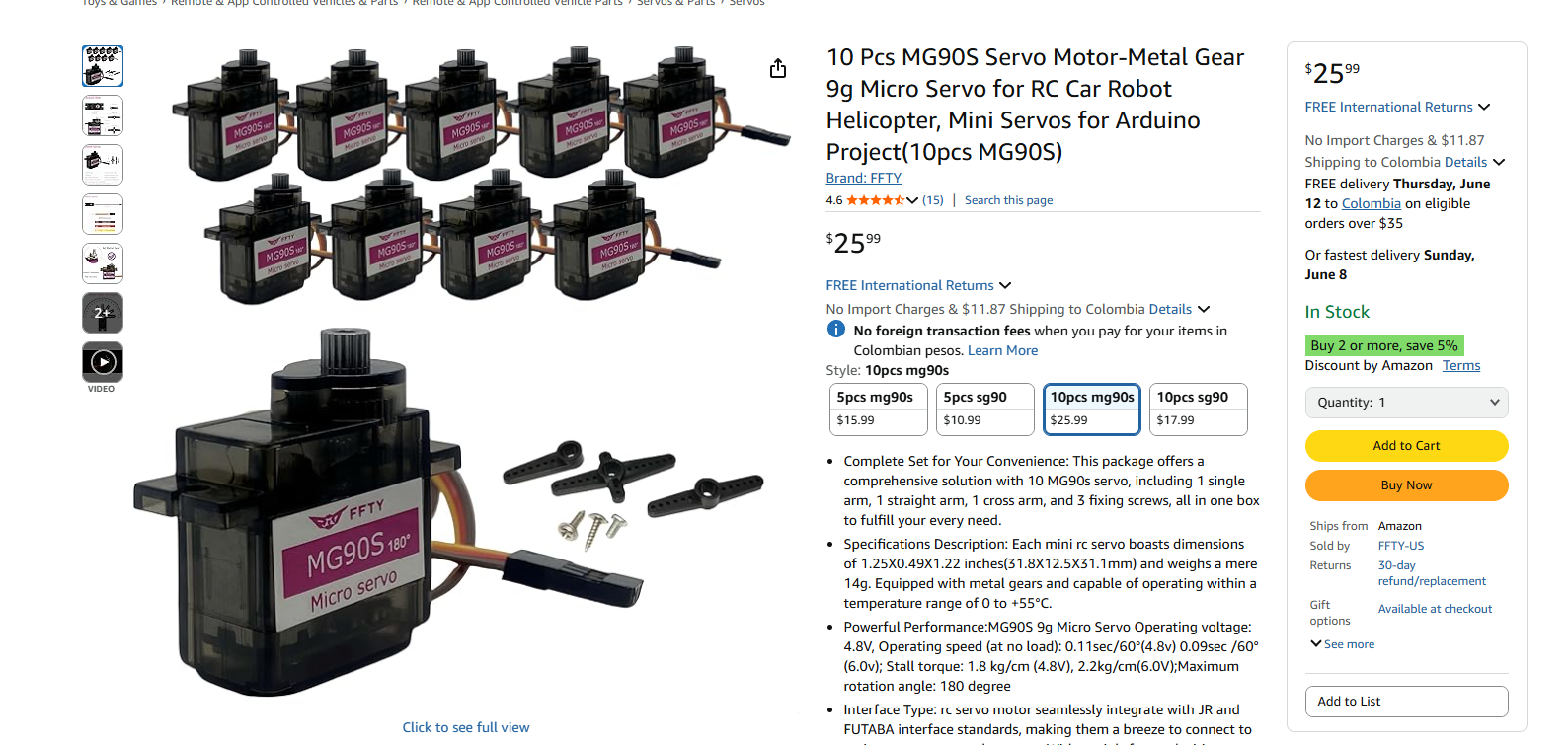
For the actuation of the fingers, I used MG90S micro servos, which are compact and provide enough torque for small robotic movements. I bought a pack of 6 servos, which allowed me to control multiple joints in the robotic hand. Each servo was connected to a custom PCB.
The custom PCB was made using copper-laminated FR4 single-side boards, which I cut and milled with the CNC machine available in the lab. This board allowed me to organize the wiring and distribute the signals and power to the different components more efficiently.
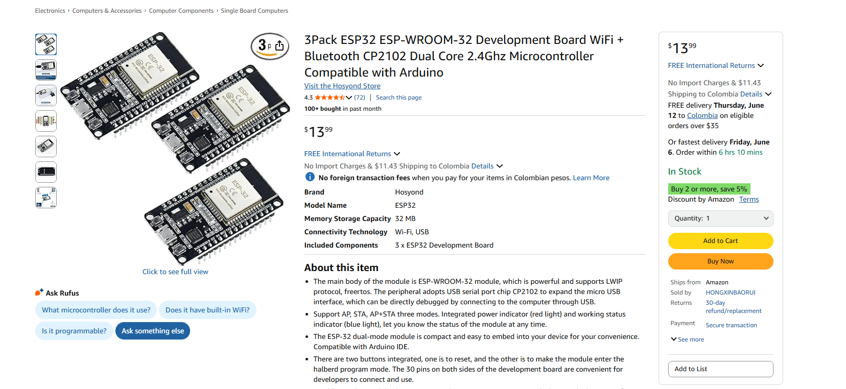
At the heart of the system is the ESP32 DevKit, a microcontroller that provides enough processing power and GPIOs for my project. It also includes WiFi and Bluetooth capabilities, which I plan to explore in future improvements.

All the components were mounted and connected manually. The design of the hand allows for each finger to move independently through the control of each servo motor. The system is powered via USB-C, and the code to control the hand was written in Python, using serial communication to send commands to the ESP32 DevKit.
How much will they cost?
| Component | Cost (COP) |
|---|---|
| ESP32 DevKit board | 70,644 |
| Servos (x6) | 46,854 |
| PLA filament (1kg) | 74,802 |
| LiPo batteries (x2) | 14,000 |
| CNC PCB materials | 40,000 |
| Step UP-DOWN | 20,000 |
| Screws, wires, etc. | 30,000 |
| Total | 319,000 COP |
| Component | Cost (USD) |
|---|---|
| ESP32 DevKit board | $17.50 |
| Servos (x6) | $11.50 |
| PLA filament (1kg) | $18.50 |
| LiPo batteries (x2) | $3.50 |
| CNC PCB materials | $10.00 |
| Step UP-DOWN | $5.00 |
| Screws, wires, etc. | $7.50 |
| Total | $73.50 |
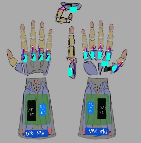
Design 2d (photoshop)
Design 3D (SolidWorks)
Simulation
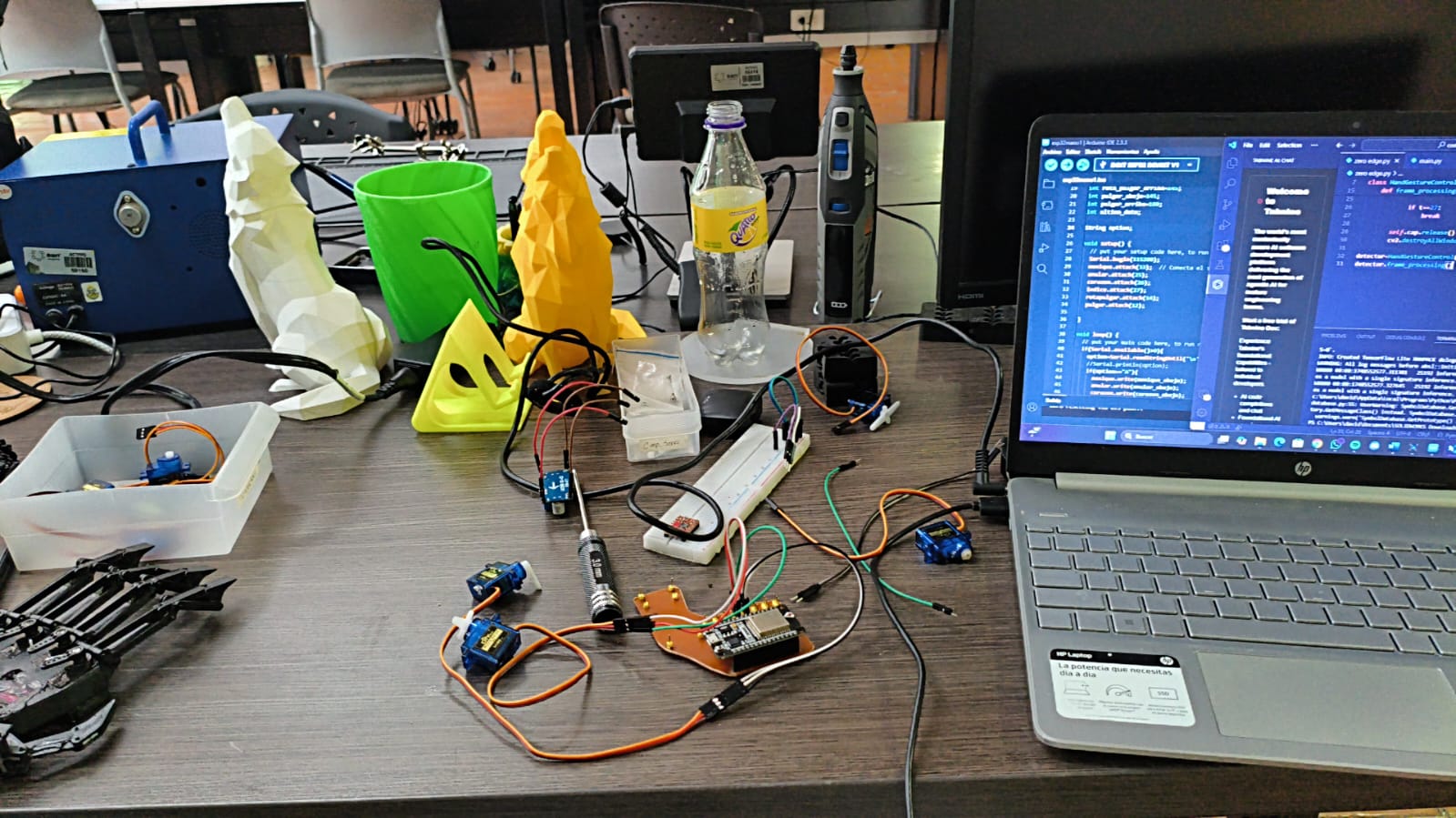
Preliminary Advances & Initial Tests
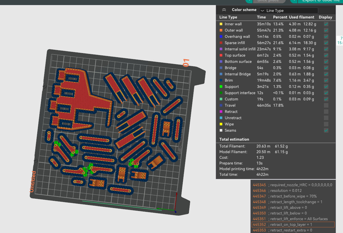
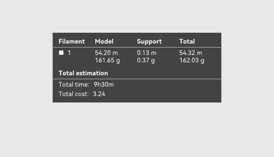
Total weight of the parts and time on the 3D printer
Finger arming
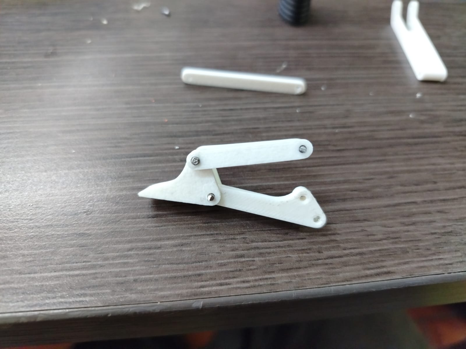
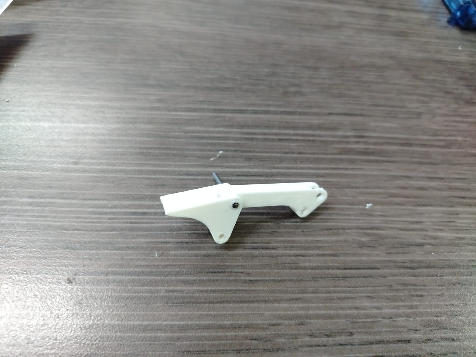
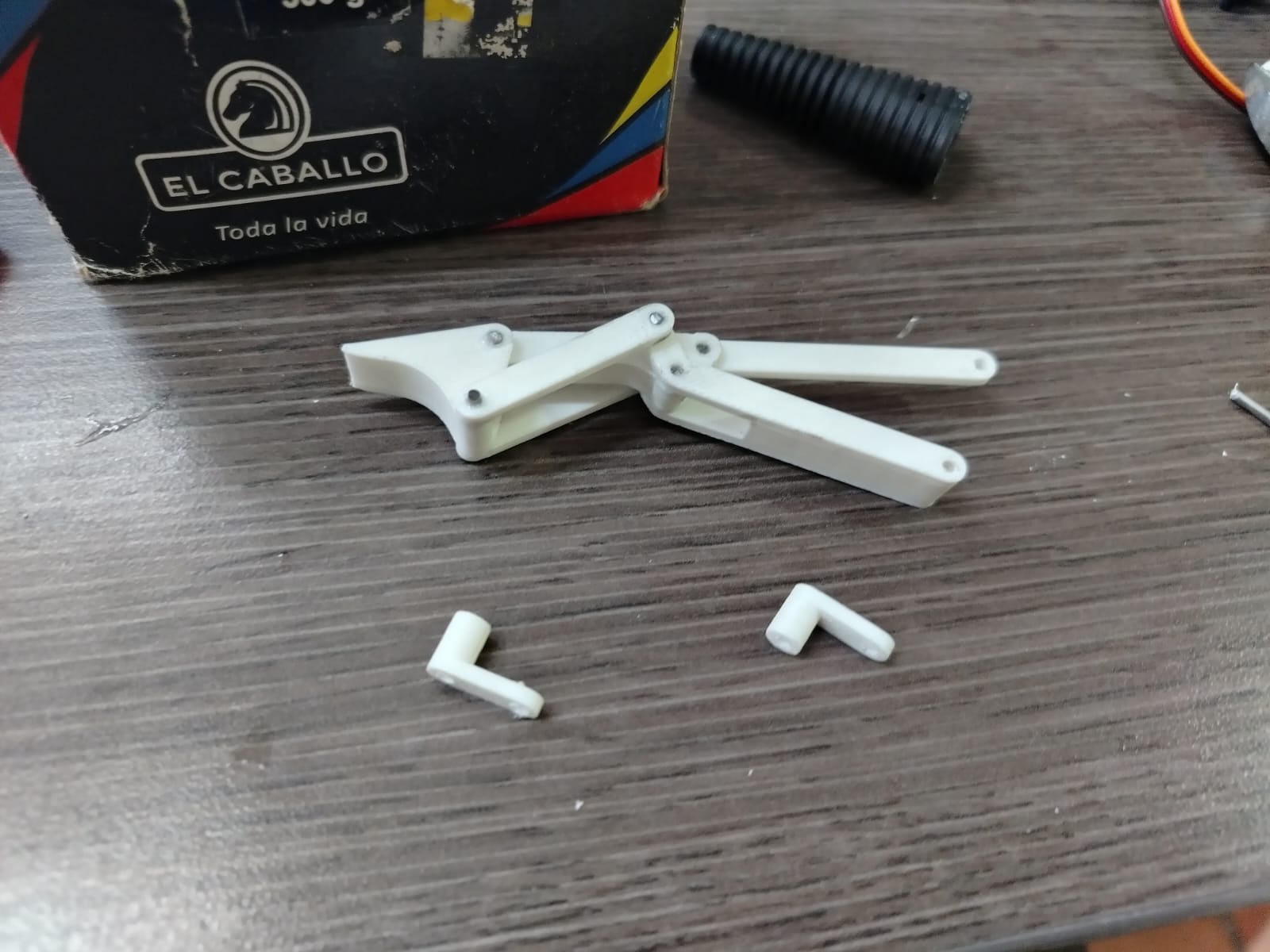
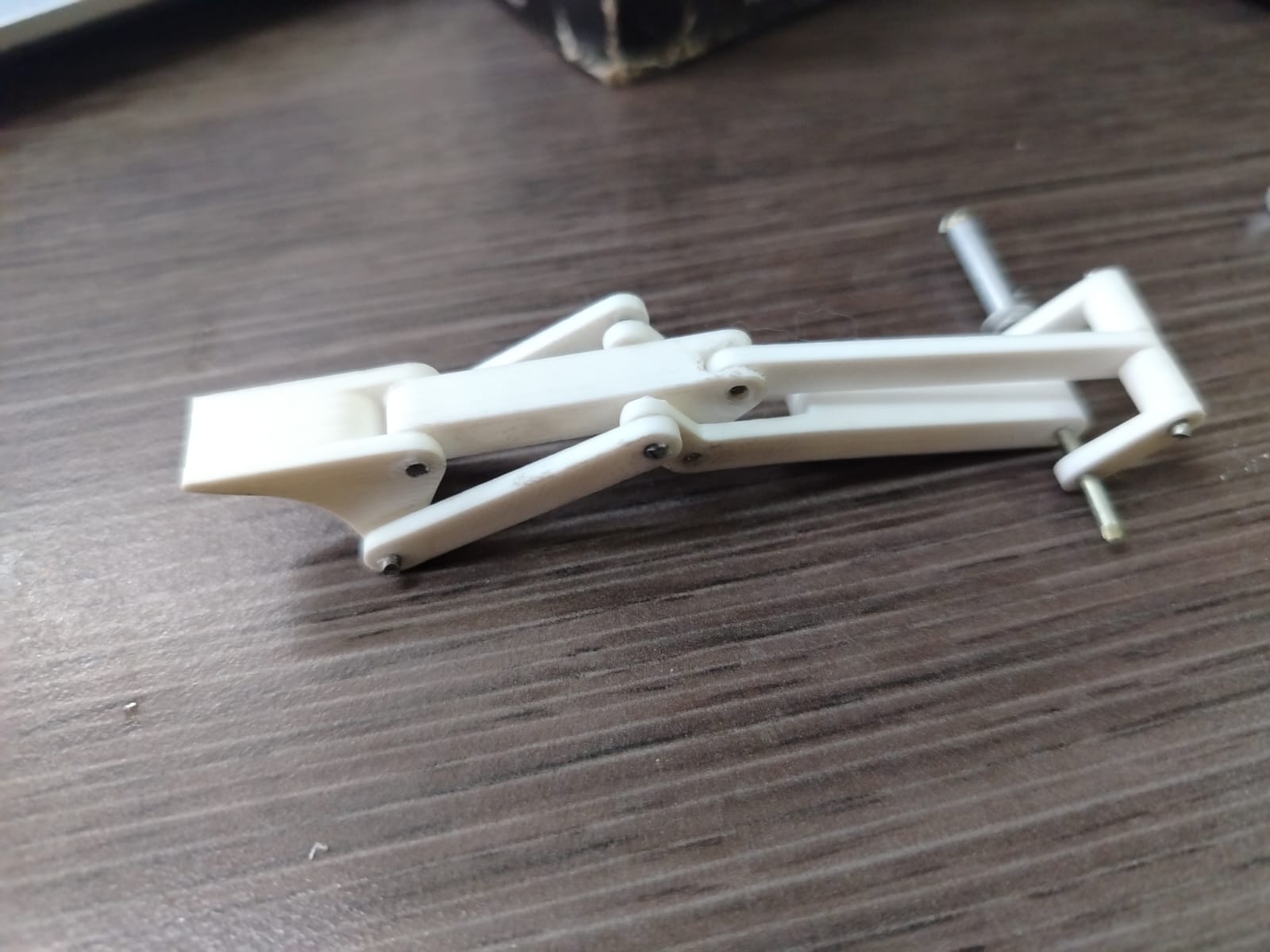
Tested the motion of the fingers, achieving basic articulation.
Key Components
- ESP32: Main control unit for vision processing and servo control.
- USB Camera: Captures human hand gestures for real-time interpretation.
- MG996R Servomotors: Controls finger and wrist articulation.
- 3D Printed Hand Parts: Fingers, palm, and structure.
- Custom-made PCB: Handles signal and power routing.
- 12V Power Supply: Powers servos and electronics.
- Four-bar Linkages: Replicate finger movements precisely.
- SolidWorks CAD Designs: Mechanical design and simulations.
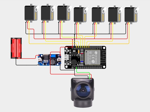
System Diagram
This diagram shows the primary system configuration for my robotic hand prototype, integrating the ESP32 microcontroller with servomotors, a custom PCB, a dual LiPo battery system, and a computer vision interface. The ESP32 receives real-time commands from a Python application using OpenCV to detect hand gestures. The servos are responsible for actuating the fingers through a four-bar linkage mechanism, while the thumb operates with a gear system for added dexterity. Due to power constraints, only the essential servos are active during continuous operation; future versions may incorporate position sensors or reduce the number of motors to optimize energy efficiency.
PCB generation in Easyeda generation
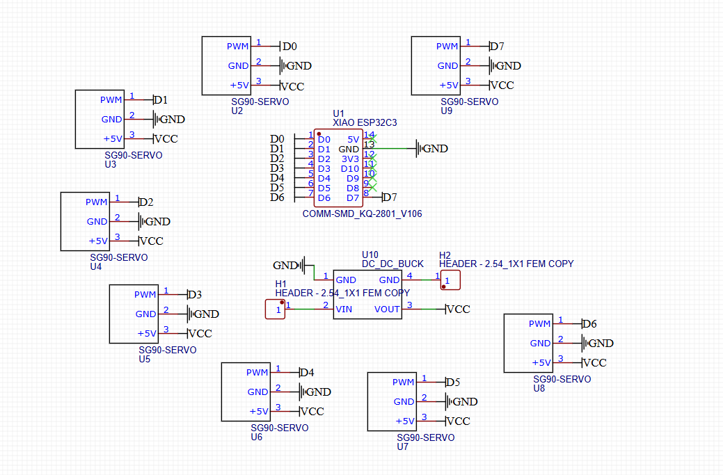
Pcb Xiao ESP32C3
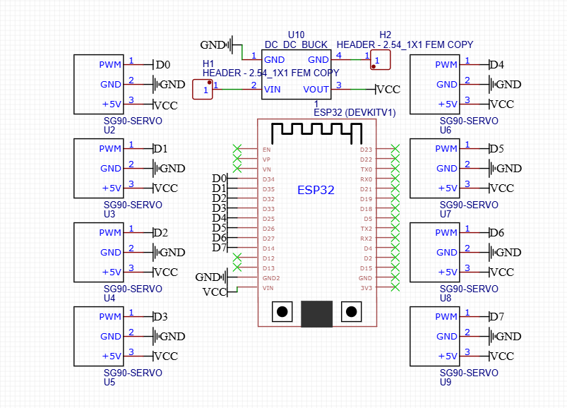
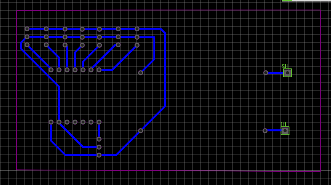
Pcb ESP32 Dev Kit
Paths Easyeda generation
Path Xiao ESP32C3
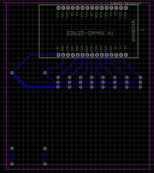
Path ESP32 Dev Kit
Fusion 360
Fusion path Xiao ESP32C3
Fusion path ESP32 Dev Kit
Fusion 360_ simulation
Simulation pcb xiao esp32c3
Simulation pcb esp32 dev kit
Simulation pcb xiao esp32c3
Simulation pcb esp32 dev kit
Preliminary PCB
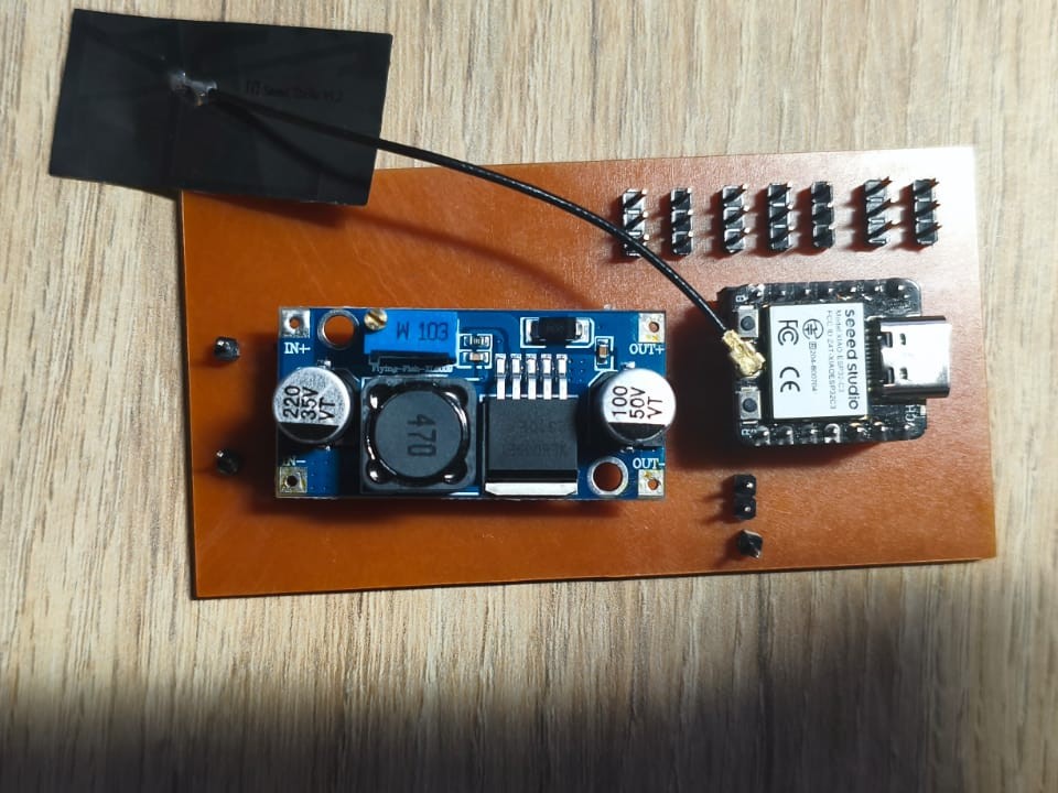
Pcb Xiao ESP32C3
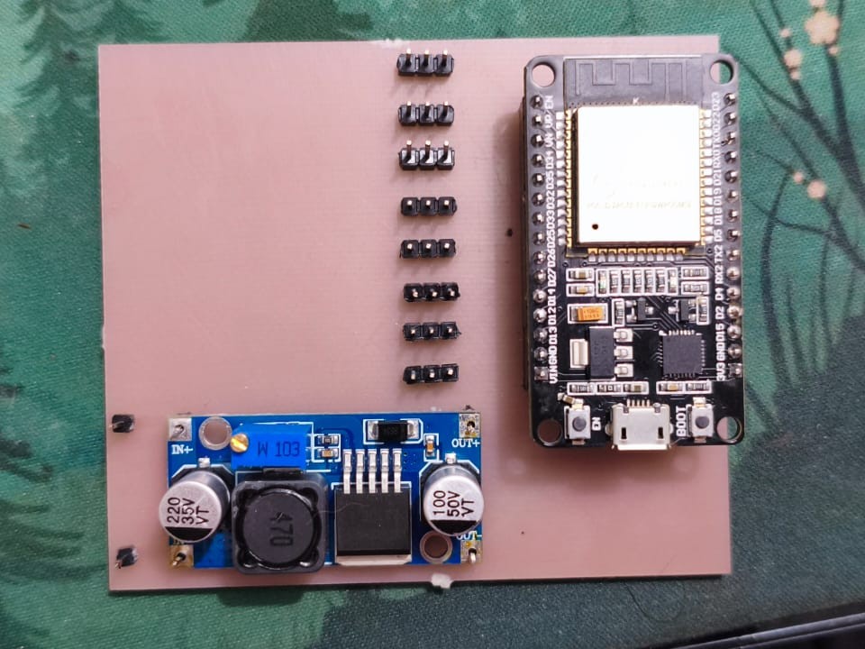
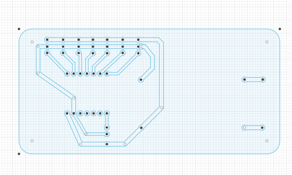
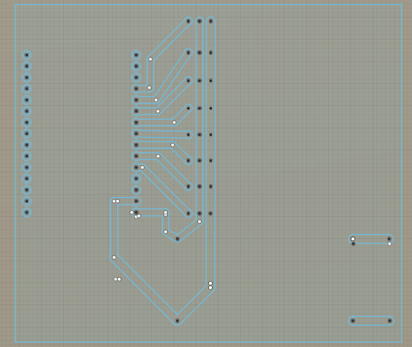
Pcb ESP32 Dev Kit
Testing with the XIAO ESP32-C3 PCB
During the tests performed with the PCB designed around the XIAO ESP32-C3, it was observed that this board could only reliably control two servo motors at a time. Several technical limitations inherent to this board explain this behavior:
- Absence of a VIN Pin:
The XIAO ESP32-C3 lacks a dedicated VIN pin for power input, unlike larger variants such as the ESP32 DevKit 1. This limits the ability to supply a stable and adequate external voltage to power both the board and multiple servos simultaneously, which typically require high current during operation. - Power Supply Using LM2596 and Batteries:
An attempt was made to power the PCB with an LM2596 voltage regulator and LiPo batteries to provide the required autonomy. However, when connecting this setup to a PC via USB for programming or monitoring, the computer experienced unexpected shutdowns or power cuts. This suggests possible overcurrent draw or a short circuit impacting the power stability. - Limitations in Energy and Current Management:
Since the XIAO ESP32-C3 lacks a VIN pin and is not designed for powering multiple servos simultaneously, the system encounters an energy bottleneck. Servos demand current spikes that the PCB cannot effectively handle, resulting in instability, poor performance, and risks to both the microcontroller and the connected computer.
Conclusion:
While the XIAO ESP32-C3 is compact and efficient for lightweight applications, it is unsuitable for systems requiring simultaneous control of multiple high-current servos. For such applications, boards with more robust power design—such as the ESP32 DevKit 1, which includes a VIN pin for external voltage supply and better current handling capabilities—are recommended.
Therefore, after these tests, it was decided to use the PCB based on the ESP32 DevKit 1 for the final implementation to ensure stable power management and reliable control of all 8 servomotors.
Testing with the ESP32 DevKit 1 PCB
Following the limitations encountered with the XIAO ESP32-C3, a PCB based on the ESP32 DevKit 1 was developed and tested. Unlike the XIAO ESP32-C3, the ESP32 DevKit 1 includes a dedicated VIN pin, which allows for a more stable and suitable external power supply for the system.
During testing, the ESP32 DevKit 1 PCB was able to successfully power and control all the servomotors required for the robotic hand. The presence of the VIN pin made it possible to supply the necessary voltage and current to both the microcontroller and the eight servos simultaneously without any instability or power interruptions.
This improved power management capability ensured reliable operation of the robotic hand, allowing smooth and coordinated movement of all fingers in real time as commanded by the gesture recognition system.
Based on these results, the ESP32 DevKit 1 PCB was chosen as the final platform for the project due to its superior power handling, stability, and suitability for controlling multiple actuators in an autonomous setup.
Arduino Code
    #include <ESP32Servo.h>

    // Define los servos de 180°
    Servo indice;
    Servo corazon;
    Servo anular;
    Servo menique;
    Servo pulgar;
    Servo rotapulgar;

    // Define los servos de 360°
    Servo derecha_izquierda;
    Servo frente_atras;

    String option;
    int arriba=180;
    int abajo=0;

    // Pines de los servos
    int pinServo180[] = {21, 22, 23, 15, 19, 32}; // Pines para los 6 servos de 180°
    int pinServo360[] = {8, 9}; // Pines para los 2 servos de 360°

    void setup() {
      Serial.begin(115200);
      indice.attach(pinServo180[0]);
      corazon.attach(pinServo180[1]);
      anular.attach(pinServo180[2]);
      menique.attach(pinServo180[3]);
      pulgar.attach(pinServo180[4]);
      rotapulgar.attach(pinServo180[5]);

      derecha_izquierda.attach(pinServo360[0]);
      frente_atras.attach(pinServo360[1]);

      pulgar.write(arriba);
      indice.write(arriba);
      corazon.write(arriba);
      anular.write(arriba);
      menique.write(arriba);
    }

    void loop() {
      if(Serial.available()>0){
        option=Serial.read();
        Serial.println(option);

        if(option=="A"){
          anular.write(abajo);
          indice.write(abajo);
          corazon.write(abajo);
          menique.write(abajo);
          pulgar.write(abajo);
        }else if(option=="B"){
          pulgar.write(arriba);
          indice.write(abajo);
          corazon.write(abajo);
          anular.write(abajo);
          menique.write(abajo);
        }
        // ...and so on with the other letters and numbers

      }else{
        Serial.println("no hay datos");
        pulgar.write(arriba);
        indice.write(arriba);
        corazon.write(arriba);
        anular.write(arriba);
        menique.write(arriba);
      }
    }
The code reflects the integration of electronics and mechanical design to mimic the complexity of human hand movement, a key goal of the Zero Edge project.
Download Project File
Download Arduino Code (.ino)Arduino Code Explanation
This section explains the Arduino sketch used to control the robotic hand prototype, focusing on how the ESP32 interacts with the servomotors and receives commands from the user.
Overview
The code controls six 180° servomotors corresponding to the fingers and thumb of the prosthetic hand, plus two 360° servomotors (currently defined for future expansions like wrist rotation). The system uses serial communication to receive commands that determine the gestures or movements of the hand.
Main Components
- ESP32Servo Library: Simplifies the control of servomotors with the ESP32.
- Six 180° Servos: Control each finger (index, middle, ring, pinky, thumb) and an additional rotational movement for the thumb.
- Two 360° Servos: (Defined but not actively used) for future motion capabilities like left-right and forward-backward wrist movements.
- Serial Communication: Commands are sent to the ESP32 through the serial port to change finger positions.
Initialization (setup)
The setup() function initializes serial communication at 115200 baud and attaches each servo to its corresponding pin. At startup, all fingers are extended (set to 180°) to ensure an open-hand position.
Main Loop (loop)
The loop() function constantly checks if there are commands available on the serial port:
- If a command is detected: The program reads the command and adjusts the positions of the servos to create a specific gesture (e.g., "A" closes all fingers).
- Each letter or number corresponds to a unique gesture: For example, "A" bends all fingers, "B" keeps the thumb up and other fingers down, and so on. This allows for a wide range of gestures based on simple serial inputs.
- If no command is received: A message “no hay datos” is printed, and the servos return to the default open position (180°).
Important Note
Currently, the code uses = (assignment) instead of == (comparison) when checking which command was received. To work correctly, replace all instances like if(option="A"){ with if(option=="A"){. This ensures proper command recognition.
How it Works
Each servo receives a .write() command that sets its angle based on the command received. This modular design makes it easy to add new gestures by expanding the if-else block with new servo angle combinations.
Potential Applications
- Robotic hand for sign language demonstration or rehabilitation purposes.
- Assistive technology for individuals with limb differences.
- Interactive educational tool to demonstrate robotics and motion control.
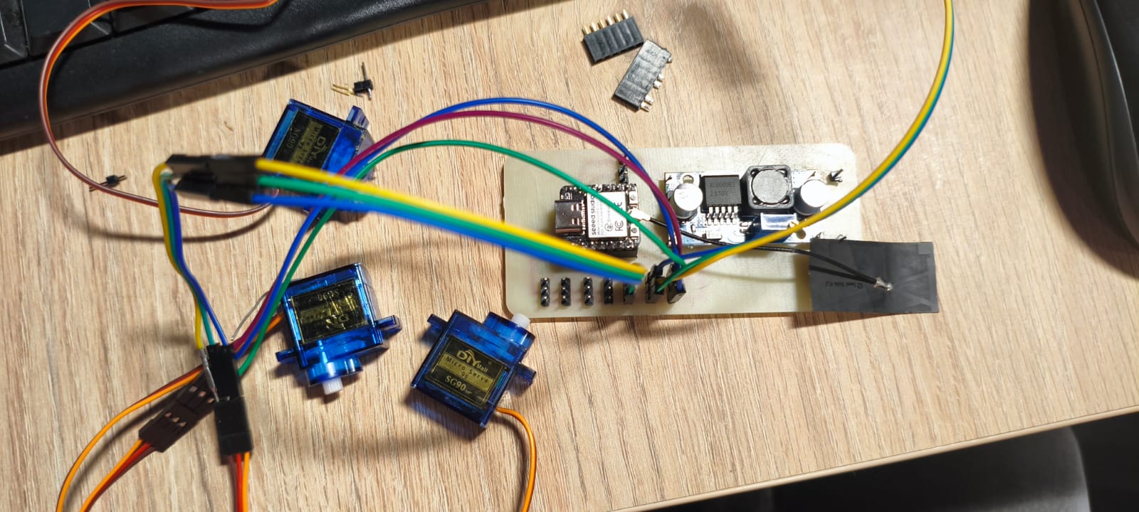
first test of the PCB
Artificial Vision and ESP32 Integration
Overview
This section describes the implementation of the artificial vision system used to detect hand gestures and communicate these commands to the ESP32 microcontroller for controlling the robotic glove’s servos.
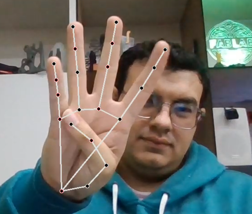
Screenshot of the OpenCV window displaying real-time hand gesture detection with landmarks and connections.
System Components
- Camera (USB webcam): Captures real-time video of the user's hand.
- OpenCV library: Handles video capture and frame processing.
- GestureDetector module: Custom module responsible for interpreting hand gestures from video frames.
- SerialCommunication module: Manages serial data exchange between the computer and the ESP32.
- ESP32 microcontroller: Receives gesture commands and actuates the servos on the robotic glove accordingly.
Software Architecture
The Python program consists of the HandGestureControl class, which integrates video capture, gesture recognition, and serial communication as follows:
class HandGestureControl:
      def __init__(self):
          # Initialize video capture and set resolution
          self.cap = cv2.VideoCapture(0)
          self.cap.set(3, 1280)  # Frame width
          self.cap.set(4, 720)   # Frame height

          # Initialize gesture detector
          self.hand_gesture = GestureDetector()

          # Initialize serial communication with ESP32
          self.communication = SerialCommunication()

      def frame_processing(self):
          # Continuous frame processing loop
          while True:
              t = cv2.waitKey(5)
              ret, frame = self.cap.read()
              # Detect gesture and get command string
              command, draw_frame = self.hand_gesture.gesture_interpretation(frame)

              # Send command to ESP32 via serial port
              self.communication.sending_data(command)

              # Display annotated frame for user feedback
              cv2.imshow('Hand gesture control', draw_frame)

              # Exit loop on ESC key press
              if t == 27:
                  break

          # Release resources and close windows
          self.cap.release()
          cv2.destroyAllWindows()
Download Project File
Download Python Code (.py)Functional Description
- Video Capture: Captures live images of the hand at 1280x720 resolution.
- Gesture Detection: Processes each frame to detect hand landmarks and classify gestures, returning a command string that corresponds to a particular hand posture or letter.
- Command Transmission: Sends the detected command string over a serial interface to the ESP32 microcontroller.
- User Feedback: Displays the video feed annotated with detected landmarks and recognized gestures for real-time monitoring.
- Loop Control: Runs continuously until the user terminates the program by pressing the ESC key.
Hand Landmark Detection Examples
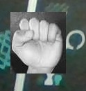
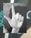
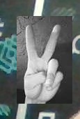
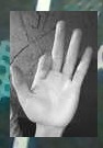
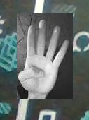
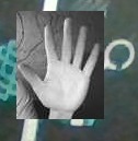
Images showing detected hand landmarks and finger keypoints used in gesture classification.
Real-Time User Interface
Integration with Robotic Glove
The ESP32 listens on the serial port for incoming commands and moves the respective servos to replicate the detected gesture physically. This closed feedback loop enables a responsive and intuitive control system for the prosthetic hand.
pre-assembly of the hand
First Test
The first test focused on verifying the servomotors' ability to control the movements of the fingers and wrist. The vision system based on OpenCV was tested to ensure that it correctly detected hand gestures. During this test, an initial calibration of the servos was performed to ensure smooth and precise movements.
first test of the robotic hand
First Test Results
- The servos responded correctly to the initial movements.
- The gesture detection through vision was accurate under good lighting conditions.
- Some calibration parameters were adjusted to improve the smoothness of finger movement.
Final Design
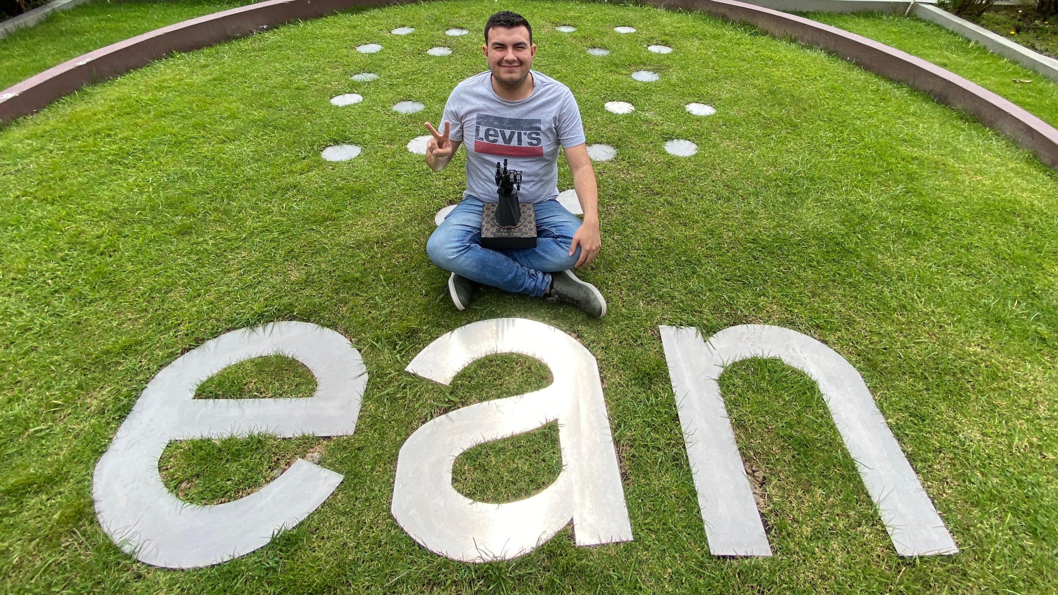
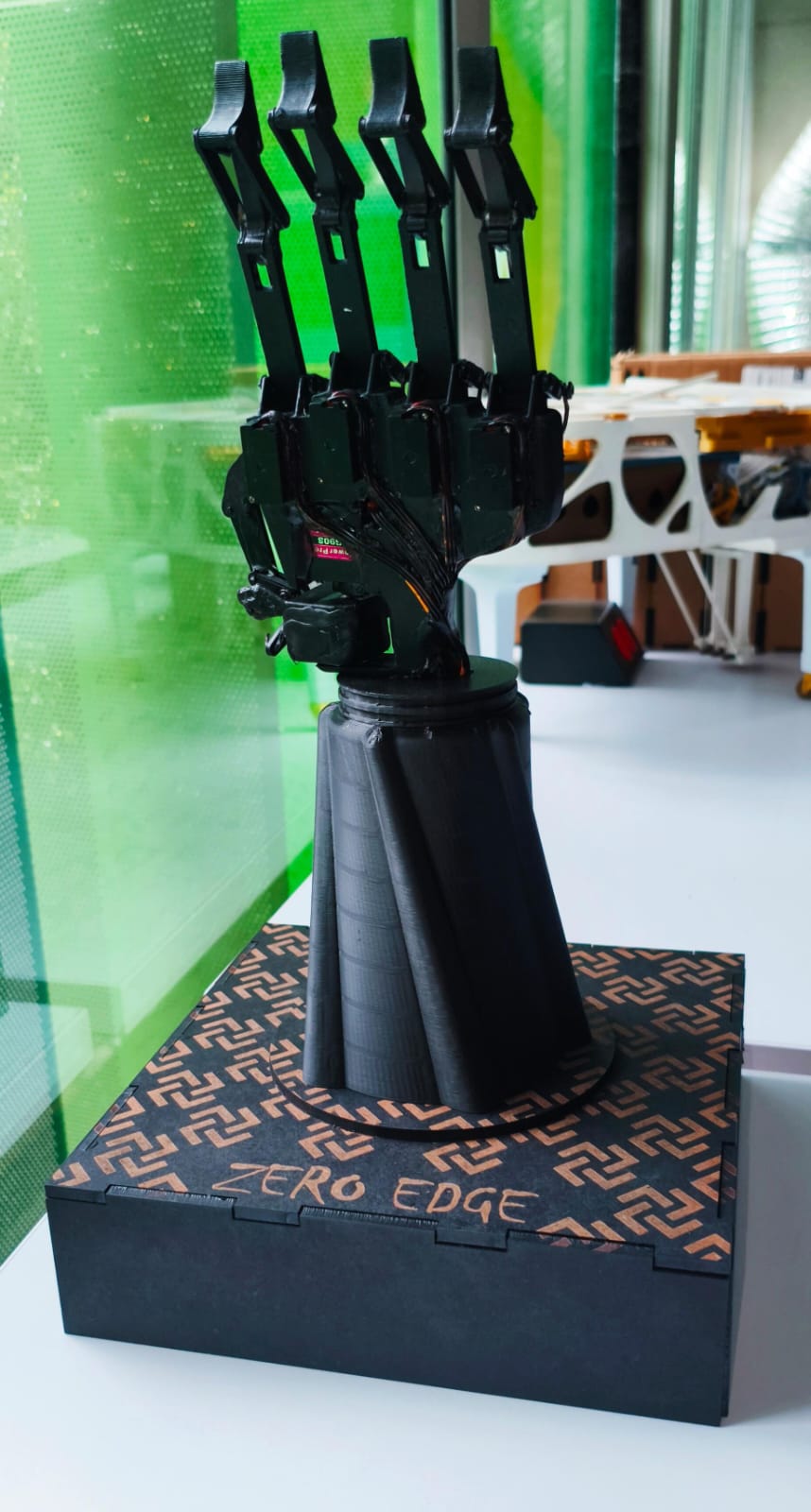
The final design of the robotic hand is a sophisticated and aesthetically refined model, featuring a sleek structure that combines both mechanical efficiency and an innovative visual appeal. The hand is mounted on a modern, minimalist base labeled "Zero Edge," which enhances its futuristic look. The mechanical structure has been designed with attention to detail, ensuring smooth articulation and flexibility at the finger joints. The fingers are equipped with precise servos for better control and movement accuracy, enabling the hand to replicate intricate gestures with high precision. The base, designed for stability, supports the hand and ensures a solid foundation during operation.
Components of the Final Design
- Optimized mechanical structure with robust and flexible finger joints.
- Use of high-quality servos for improved articulation of the fingers and wrist.
- Aesthetic and functional base labeled "Zero Edge" providing stability and visual appeal.
- Enhanced ergonomics for smoother and more reliable movements.
- Future plans for integration with advanced control systems, enhancing response time and accuracy.
Results
Video 1: Hand Following My Movements
This video demonstrates how the robotic hand replicates in real time the movements of my fingers and wrist through the vision system. You can observe the response of the servomotor system as I follow different hand gestures.
Video 2: Hand Moving Remotely
This video demonstrates how the robotic hand can be remotely controlled, simulating an environment where it operates from a distance without direct contact. You can see how the system reacts to commands sent from a remote device.
Future Improvements
- Enhance gesture recognition under various lighting conditions for better reliability.
- Expand the gesture library for more complex sign language interpretation.
- Optimize power consumption to extend operational time and improve portability.
- Integrate AI-driven translation for seamless conversion of sign language to speech.
Conclusions
The Zero Edge robotic hand successfully demonstrates the integration of computer vision and robotics for real-time gesture recognition. Using OpenCV and MediaPipe, the system can accurately detect and replicate hand gestures, providing an interactive and educational tool for learning sign language.
The mechanical design, based on four-bar linkages, ensures precise finger movements with a lightweight and durable 3D printed structure. The integration of the ESP32 microcontroller and custom PCB ensures reliable power and motor control, with LiPo batteries providing continuous operation.
Real-time and remote control capabilities open new opportunities for interactive learning and virtual education. The open-source nature of the project enhances accessibility, allowing others to contribute or adapt it for various applications.
The future integration of AI for translating sign language into spoken language will enhance communication between individuals using sign language and those who do not understand it, further expanding the project's impact.