- design, build and connect wired or wireless node(s) with network or bus addresses and a local input and/or output devices
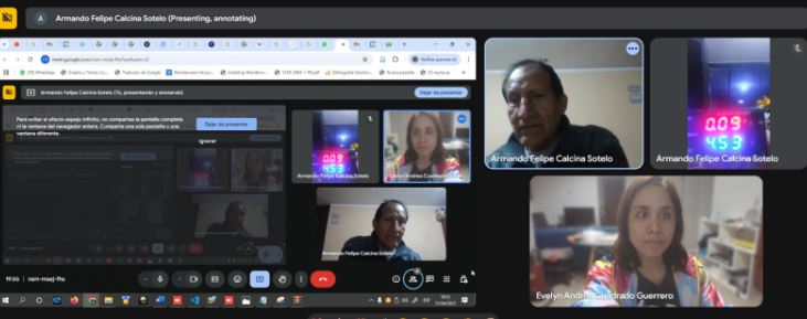
We started week 11, and our instructor, Ulises, gave us a masterclass on embedded networks and communications. In the video, he offers a detailed explanation of the MQTT protocol, programming for sensor and module operation, the roles of publishers and subscribers, and how to manage the Arduino IDE development environment.
Link to watch the video.
MQTT
MQTT (Message Queuing Telemetry Transport) is a messaging protocol for restricted low-bandwidth networks and extremely high-latency IoT devices. Since Message Queuing Telemetry Transport is specialized for low-bandwidth, high-latency environments, it is an ideal protocol for machine-to-machine (M2M) communication. online simulator to blink an LED.MQTT consists of several layers within networking and communication. Networks enable the interconnection of devices in various configurations, facilitating communication between them. Communication protocols operate at different layers of the OSI model. The transport layer, such as TCP (Transmission Control Protocol), is responsible for ensuring the reliable transmission of data between devices. Meanwhile, the network layer, such as IP (Internet Protocol), handles packet addressing across the network.
MQTT operates in the application layer, which is a higher layer in the OSI model. This means that MQTT relies on transport protocols like TCP for message transmission between devices. Within the communication protocols, MQTT uses a broker, which is a central server that facilitates communication between devices such as sensors, controllers, and users.
MQTT Components
- Broker: The central server that routes messages between clients.
- Publisher: Sends data to a topic.
- Subscriber: Listens to a topic and receives data.
- Topic: A string-based path like
sensors/temp.
Mqtt installation
To install MQTT, we follow the following steps:
Go to the official site
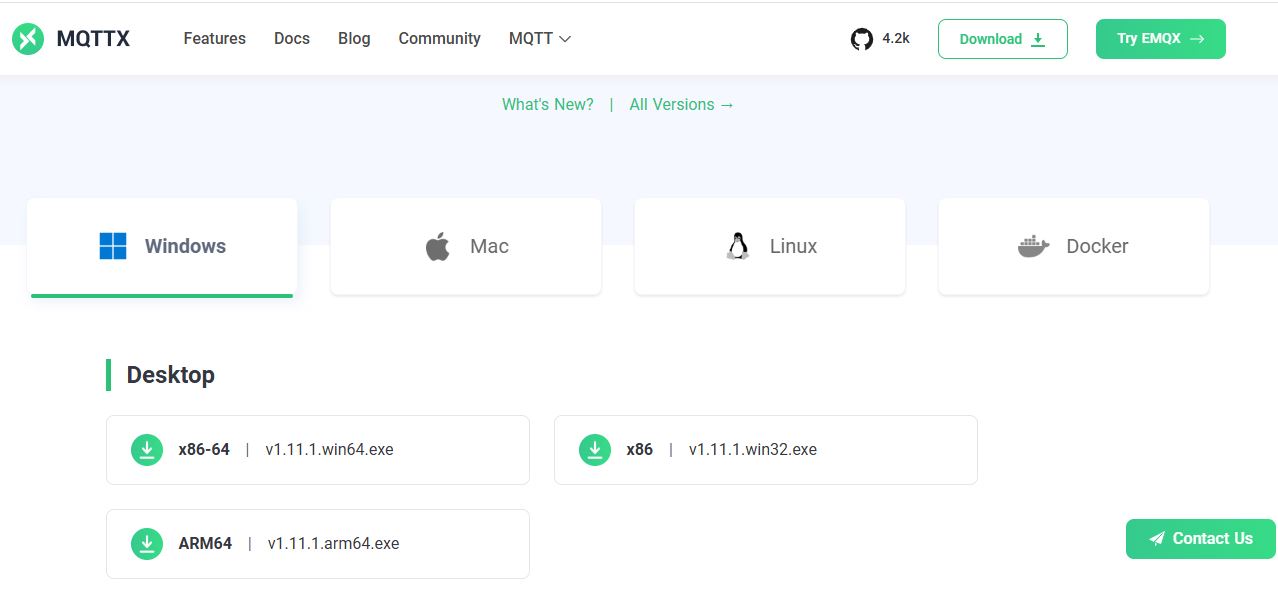
We locate the operating system of our machine, in my case Windows, the installer for Windows will be downloaded.
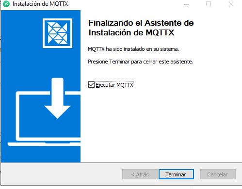
Once the installation is executed, it is finished
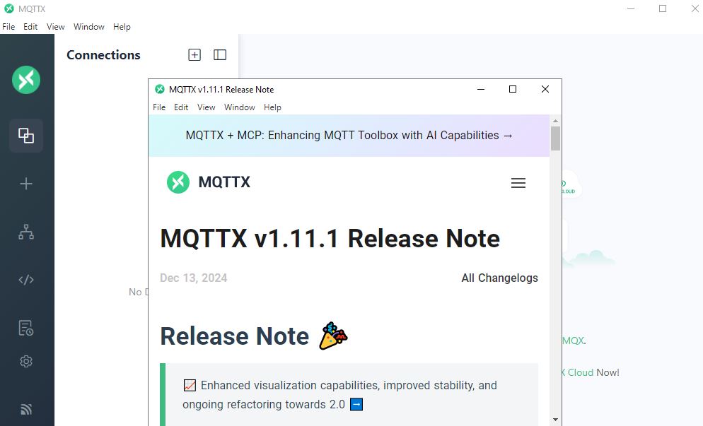
the program was installed correctly
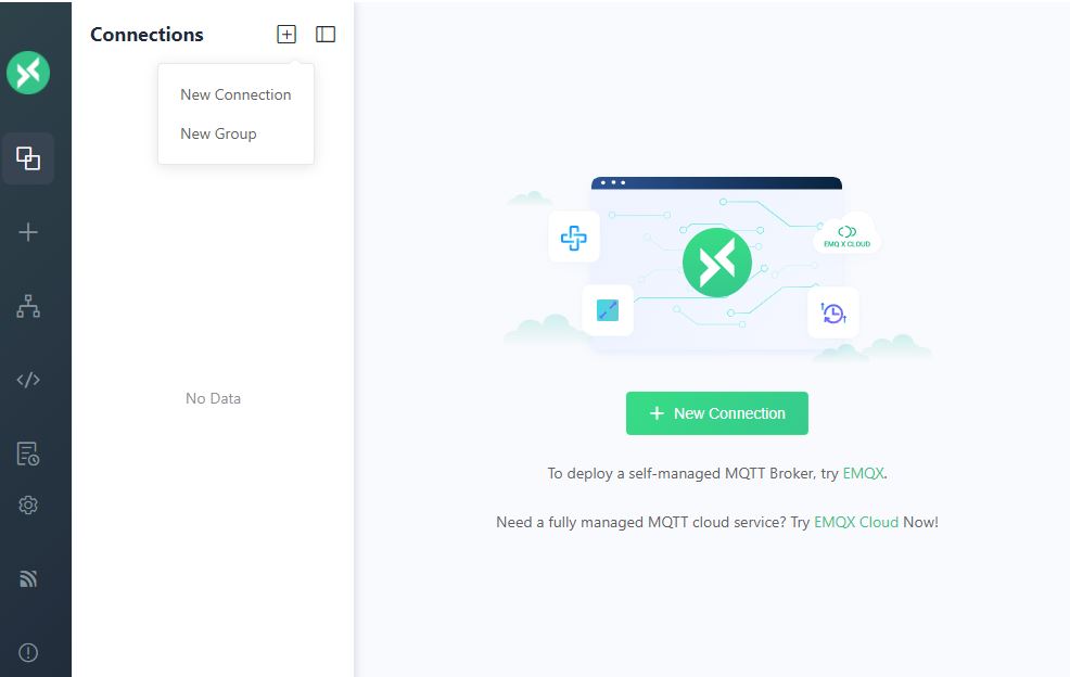
Once the interface is open, click on new connection
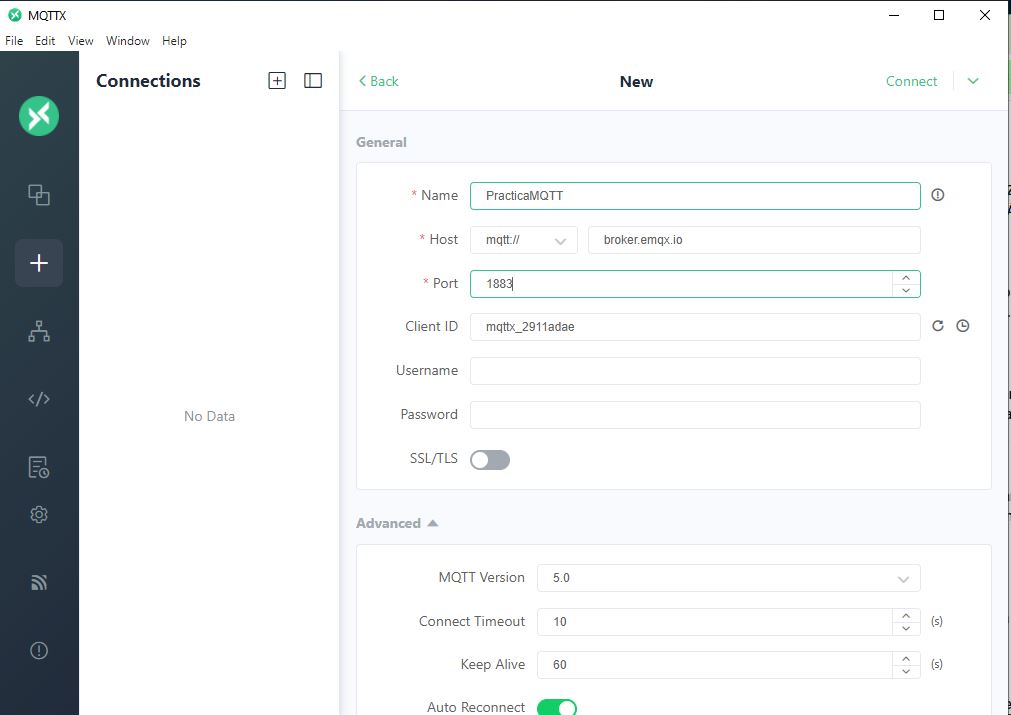
A new connection opens, where we have to fill out the required fields, as this information will allow other users in different locations to connect via MQTT
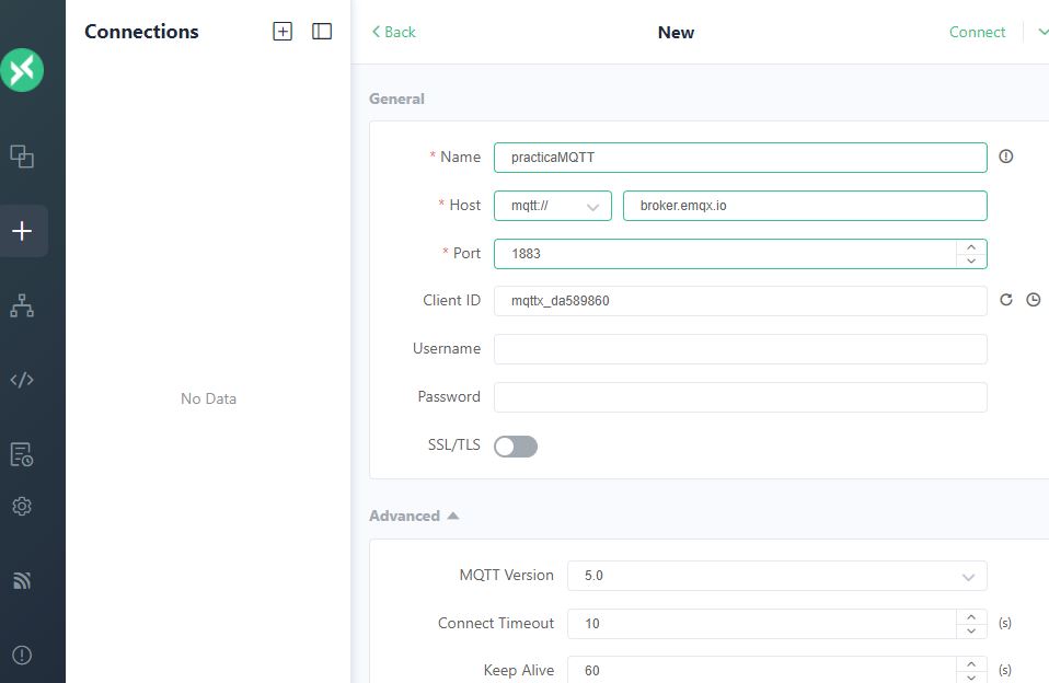
The data was filled in as shown in the image, and the name was practicaMQTT.
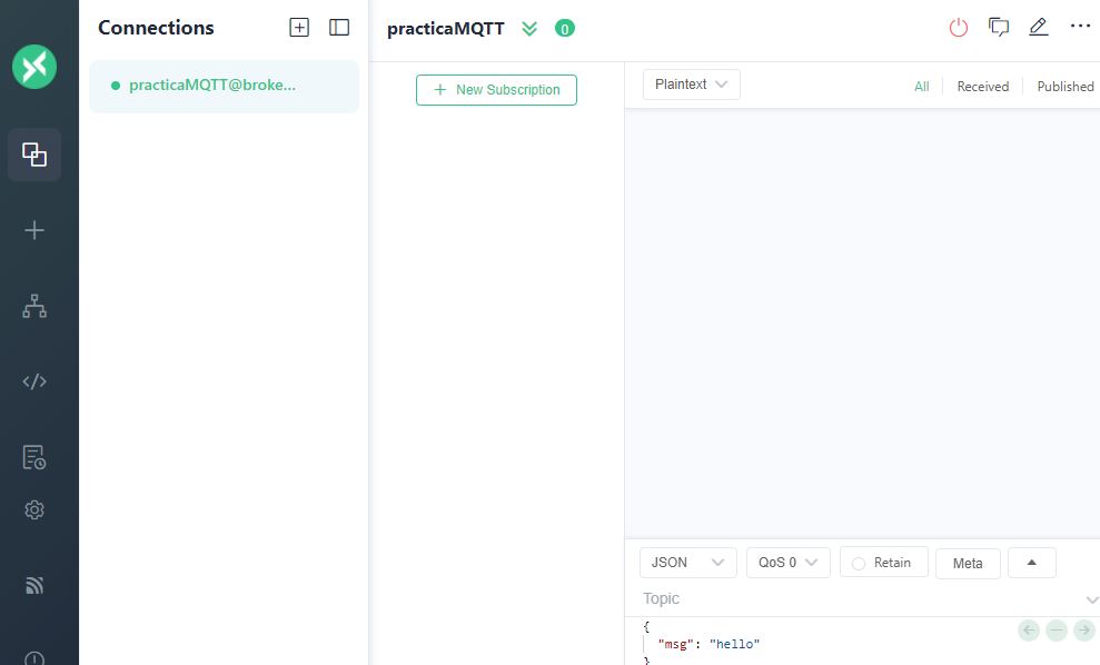
The new PracticaMQTT connection was generated
Now that we have some prior knowledge of how the MQTT protocol works, let's build a node or a network of wired or wireless nodes that allow us to control physical devices using messages transmitted through an MQTT broker.
DC motor control via MQTT subscription with ESP32-C3
In this first step, we will design a subscriber node using an ESP32-C3 board that will control a DC motor based on commands received in a specific MQTT topic. This node connects to a Wi-Fi network and listens for messages indicating actions for the motor: move forward, reverse, or stop.
we will follow the following steps:
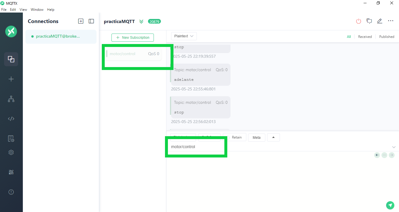
We have created a new subscription, with the topic motor/control
A publishing node was configured to manually send commands ("forward," "backward," "stop") to the motor/control topic using MQTT.
This allows us to verify the connection, sending and correct reception of messages between devices, without integrating sensors or actuators yet. After that, we go to the Arduino IDE environment to install libraries and load the code.
Steps to upload the code to Arduino IDE:
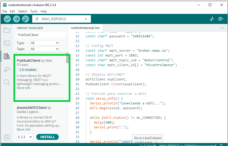
How to Install the PubSubClient Library in Arduino IDE
- Open the Arduino IDE on your computer.
- Go to the menu Sketch > Include Library > Manage Libraries...
- In the Library Manager window, enter
PubSubClient in the search bar.
- Look for the library authored by Nick O'Leary.
- Click the Install button to install the library.
- Wait for the installation to complete.
- Close the Library Manager and you are ready to use
PubSubClient in your projects.
installation according to the library
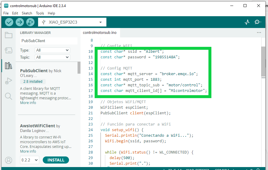
In the code we define basic parameters for MQTT communication, such as: MQTT Broker, Broker Port and Topic.
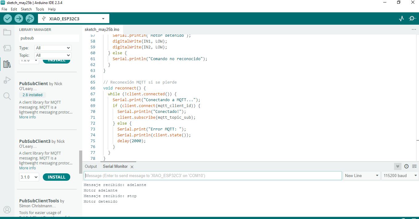
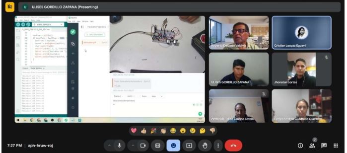
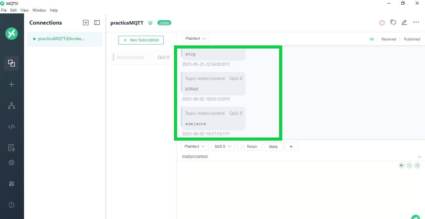
Once the code was loaded, the serial monitor was opened to confirm that the messages were being listened to.
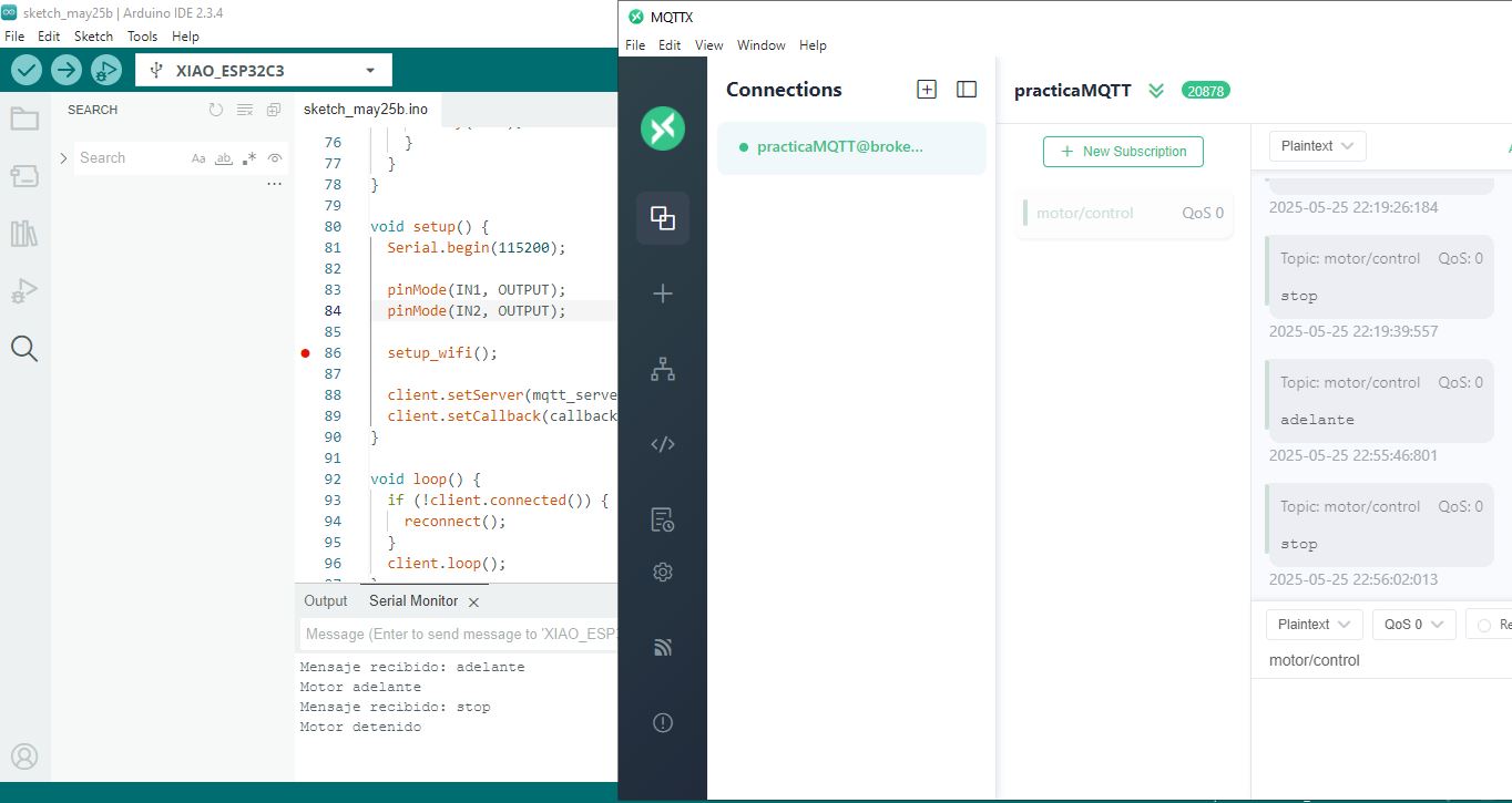
Messages were published via MQTT such as: "forward" → the engine started to rotate, "stop" → the engine stopped.
Complete Code
#include <Arduino.h>
#include <WiFi.h>
#include <PubSubClient.h>

// Motor pins
const int IN1 = 2; // GPIO2
const int IN2 = 4; // GPIO4

// WiFi config
const char* ssid = "Albert";
const char* password = "19855148A";

// MQTT config
const char* mqtt_server = "broker.emqx.io";
const int mqtt_port = 1883;
const char* mqtt_topic_sub = "motor/control";
const char mqtt_client_id[] = "Micontrolmotor";

// WiFi/MQTT objects
WiFiClient espClient;
PubSubClient client(espClient);

// Function to connect to WiFi
void setup_wifi() {
  Serial.println("Connecting to WiFi...");
  WiFi.begin(ssid, password);

  while (WiFi.status() != WL_CONNECTED) {
    delay(500);
    Serial.print(".");
  }

  Serial.println("\nWiFi connected");
  Serial.print("IP: ");
  Serial.println(WiFi.localIP());
}

// Function to handle received MQTT messages
void callback(char* topic, byte* payload, unsigned int length) {
  String msg;
  for (int i = 0; i < length; i++) {
    msg += (char)payload[i];
  }
  msg.trim();
  Serial.print("Message received: ");
  Serial.println(msg);

  if (msg == "adelante") {
    Serial.println("Motor forward");
    digitalWrite(IN1, HIGH);
    digitalWrite(IN2, LOW);
  } else if (msg == "atras") {
    Serial.println("Motor backward");
    digitalWrite(IN1, LOW);
    digitalWrite(IN2, HIGH);
  } else if (msg == "stop") {
    Serial.println("Motor stopped");
    digitalWrite(IN1, LOW);
    digitalWrite(IN2, LOW);
  } else {
    Serial.println("Unknown command");
  }
}

// MQTT reconnection function
void reconnect() {
  while (!client.connected()) {
    Serial.print("Connecting to MQTT...");
    if (client.connect(mqtt_client_id)) {
      Serial.println("Connected!");
      client.subscribe(mqtt_topic_sub);
    } else {
      Serial.print("MQTT Error: ");
      Serial.println(client.state());
      delay(2000);
    }
  }
}

void setup() {
  Serial.begin(115200);

  pinMode(IN1, OUTPUT);
  pinMode(IN2, OUTPUT);

  setup_wifi();

  client.setServer(mqtt_server, mqtt_port);
  client.setCallback(callback);
}

void loop() {
  if (!client.connected()) {
    reconnect();
  }
  client.loop();
}
In this first step, the ESP32-C3 XIAO was configured as an MQTT subscriber.
The module was connected to the Wi-Fi network and the MQTT broker.
Through an external application, messages were sent to the motor/control topic.
Upon receiving the 'forward' message, the motor was activated.
When 'stop' was sent, the motor stopped, demonstrating that MQTT communication was working correctly.
Design and Implementation of IoT Nodes with ESP32 for Motor Control via MQTT
1. Introduction
This project involves designing and building two wireless IoT nodes using ESP32 boards that communicate
over the MQTT protocol via a WiFi network to control a DC motor based on distance measurements from an ultrasonic sensor.
2. Objective
To design, build, and connect wireless nodes with network addresses and local input/output devices to control a DC motor
based on readings from an ultrasonic sensor.
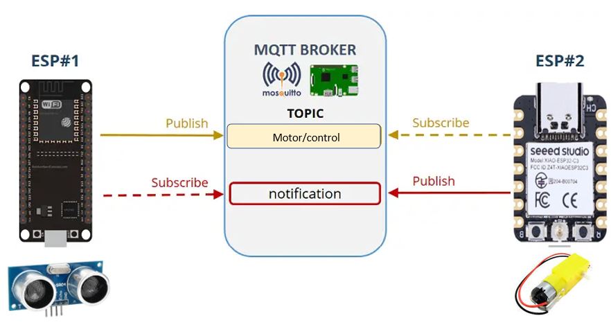
3. System Description
3.1 Nodes involved
-
Sensor Node (ESP32 Dev)
Input: HC-SR04 ultrasonic sensor
Function: Measures distance and publishes commands to the MQTT broker.
-
Actuator Node (ESP32-C3 XIAO)
Output: DC motor connected to GPIO pins
Function: Subscribes to MQTT messages and controls the motor based on received commands.
3.2 Communication
- Wireless WiFi connection with IP addresses assigned to each node.
- Public MQTT broker (
broker.emqx.io) acting as a message bus between nodes.
- Use of MQTT topic
"motor/control" for sending and receiving commands.
ESP32 Publisher (Sensor ultrasónico)
#include <WiFi.h>
#include <PubSubClient.h>

const char* ssid = "TU_SSID";
const char* password = "TU_PASSWORD";

const char* mqtt_server = "broker.emqx.io";
const int mqtt_port = 1883;
const char* topic = "motor/control";

WiFiClient espClient;
PubSubClient client(espClient);

// Pines del sensor
const int trigPin = 5;
const int echoPin = 18;

void setup_wifi() {
  WiFi.begin(ssid, password);
  while (WiFi.status() != WL_CONNECTED) {
    delay(500);
  }
}

void setup() {
  Serial.begin(115200);
  pinMode(trigPin, OUTPUT);
  pinMode(echoPin, INPUT);

  setup_wifi();
  client.setServer(mqtt_server, mqtt_port);
}

void loop() {
  if (!client.connected()) {
    while (!client.connected()) {
      client.connect("ESP32-Sensor");
    }
  }

  client.loop();

  // Medir distancia
  digitalWrite(trigPin, LOW);
  delayMicroseconds(2);
  digitalWrite(trigPin, HIGH);
  delayMicroseconds(10);
  digitalWrite(trigPin, LOW);

  long duration = pulseIn(echoPin, HIGH);
  float distance = duration * 0.034 / 2;

  Serial.print("Distancia: ");
  Serial.println(distance);

  if (distance < 20.0) {
    client.publish(topic, "adelante");
  } else {
    client.publish(topic, "stop");
  }

  delay(1000);
}
Code Explanation
This ESP32 program measures distance using an HC-SR04 ultrasonic sensor and communicates the results via MQTT.
- Initializes WiFi connection and MQTT client with the specified broker.
- Configures
trigPin (output) and echoPin (input) pins to control the ultrasonic sensor.
- Generates a trigger pulse to measure echo time using
pulseIn().
- Calculates distance based on pulse duration and speed of sound.
- Publishes to the MQTT topic
motor/control the message "adelante" if distance is less than 20 cm, or "stop" otherwise.
- Keeps the MQTT connection active with automatic reconnection if lost.
ESP32 Subscriber (Control motor)
#include <WiFi.h>
#include <PubSubClient.h>

const int IN1 = 2;
const int IN2 = 4;

const char* ssid = "TU_SSID";
const char* password = "TU_PASSWORD";

const char* mqtt_server = "broker.emqx.io";
const int mqtt_port = 1883;
const char* topic = "motor/control";

WiFiClient espClient;
PubSubClient client(espClient);

void callback(char* topic, byte* payload, unsigned int length) {
  String msg;
  for (int i = 0; i < length; i++) {
    msg += (char)payload[i];
  }
  msg.trim();

  if (msg == "adelante") {
    digitalWrite(IN1, HIGH);
    digitalWrite(IN2, LOW);
  } else if (msg == "stop") {
    digitalWrite(IN1, LOW);
    digitalWrite(IN2, LOW);
  }
}

void reconnect() {
  while (!client.connected()) {
    if (client.connect("ESP32-Motor")) {
      client.subscribe(topic);
    } else {
      delay(2000);
    }
  }
}

void setup() {
  Serial.begin(115200);
  pinMode(IN1, OUTPUT);
  pinMode(IN2, OUTPUT);

  WiFi.begin(ssid, password);
  while (WiFi.status() != WL_CONNECTED) {
    delay(500);
  }

  client.setServer(mqtt_server, mqtt_port);
  client.setCallback(callback);
}

void loop() {
  if (!client.connected()) {
    reconnect();
  }
  client.loop();
}
Code Explanation
This ESP32 program connects to WiFi and an MQTT broker to control a DC motor.
- Subscribes to the
motor/control topic.
- Receives MQTT messages to start ("adelante") or stop ("stop") the motor.
- Controls motor pins
IN1 and IN2 accordingly.
- Handles reconnection if MQTT connection drops.
Results
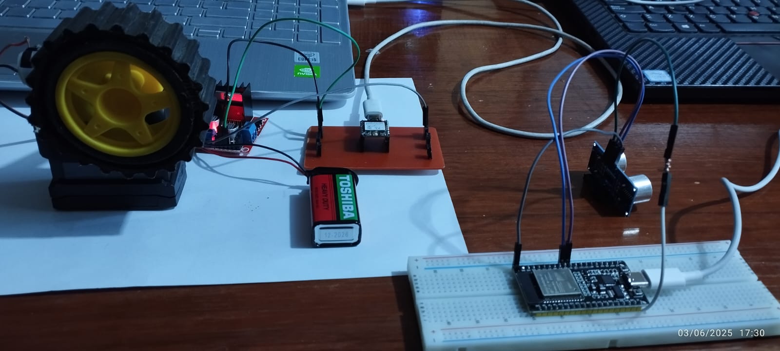
This video demonstrates the operation of a motor control system using two ESP32 microcontrollers.
The ESP32 Dev Kit is connected to an ultrasonic sensor that measures object distance. When an object is detected within 20 centimeters, it sends an "adelante" message via the MQTT protocol. If no object is nearby, it sends "stop".
The ESP32-C3 XIAO, acting as the MQTT subscriber, receives these messages and controls a DC motor through an H-bridge driver. Upon receiving "adelante", the motor turns on; when it receives "stop", it turns off.
This setup showcases wireless communication and control using MQTT based on sensor input.
Did you have any problems?
During the first test of the project, an issue arose related to the motor's battery power supply. Although MQTT messages were sent and received correctly, the motor remained stopped. After replacing the battery with a new one, the motor operated properly, indicating that the problem was likely caused by insufficient current from the initial battery.
Conclusions
Implementing MQTT communication between two ESP32 boards proved effective in achieving real-time motor control based on distance sensing. The ESP32 Dev Kit, as the publisher, successfully detected nearby objects using an ultrasonic sensor and sent control messages using MQTT. The ESP32-C3 XIAO, as the subscriber, received these messages and responded accurately by starting or stopping the motor. This project demonstrates the practical application of IoT concepts by showing how microcontrollers, sensors, and actuators can interact using wireless protocols. Overall, the system performed reliably and can be further improved by adding features such as motor speed control. This exercise will definitely help me with my final project.
Link to files used this week
1. MQTTmotor.ino
2. MQTTultrasonic.ino

.jpeg)