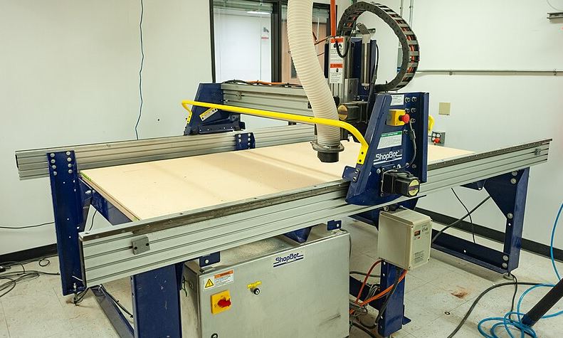
- Make (design+mill+assemble) something big (~meter-scale)
- Extra credit: don't use fasteners or glue
- Extra credit: include curved surfaces
To complete this project, three types of joints were used to connect the pieces precisely and functionally. The choice of joint type is crucial to ensure the stability, durability, and ease of assembly of the parts. Each part is designed to adapt the assembly to different design and functional needs. Each type has its specific advantages, whether it provides a stronger, more flexible, or more adjustable connection.
Design of 2D plans
The first step is to create a 2D drawing using CAD software, in this case we will use SolidWorks.. The plan is then drawn with the corresponding dimensions, joint shapes, angles, and component views of the parts.
Design piece 1
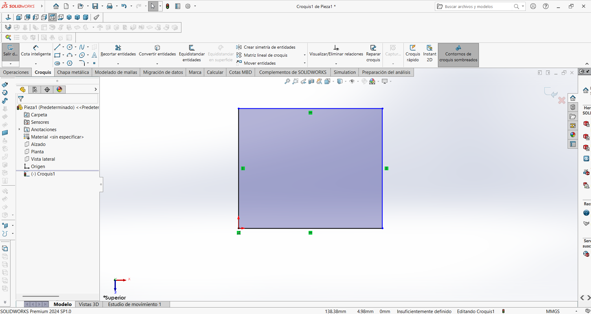
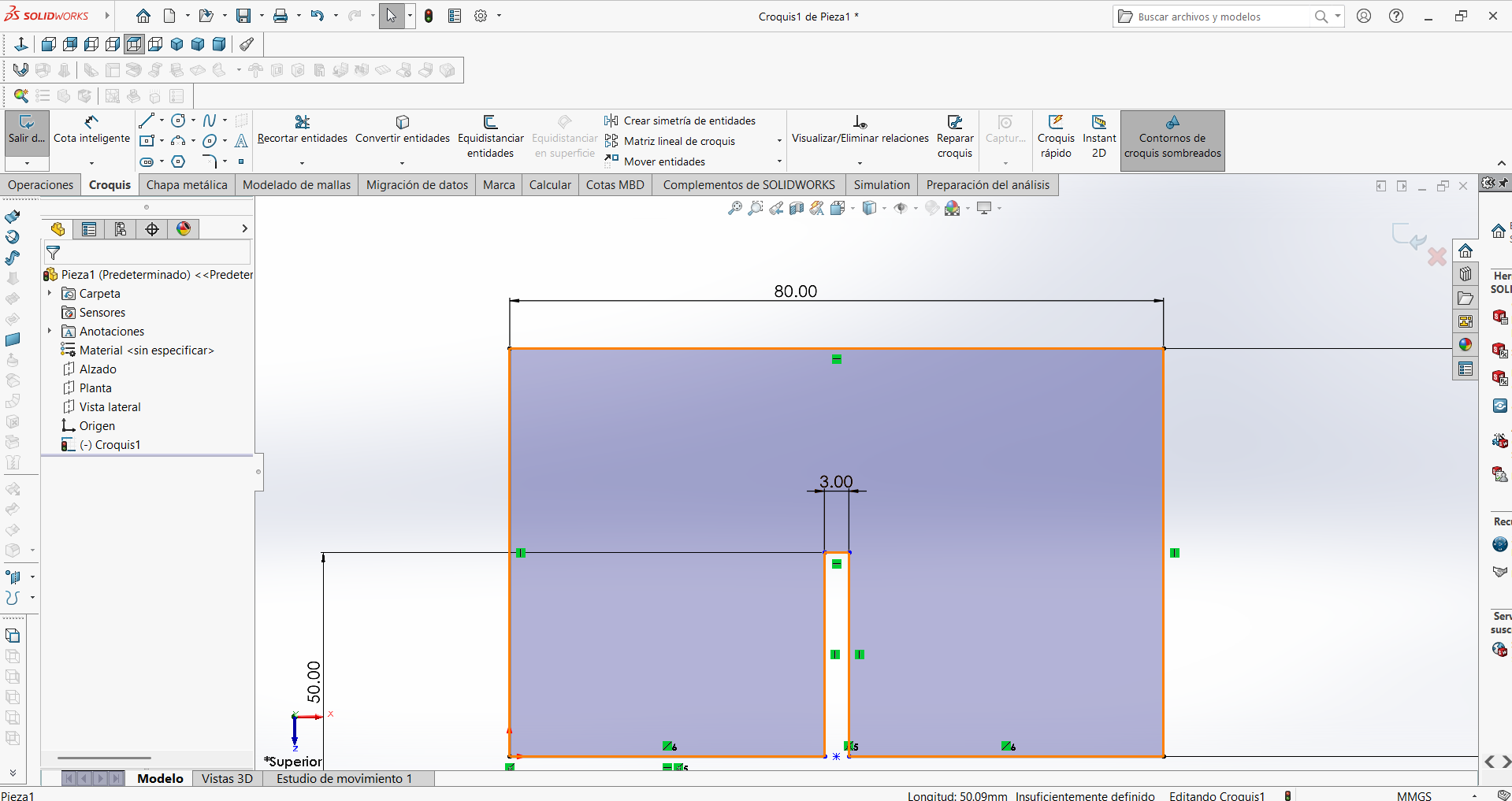
STEP 1: The initial rectangular design was completed so that the dimensions could be added with the corresponding measurements.
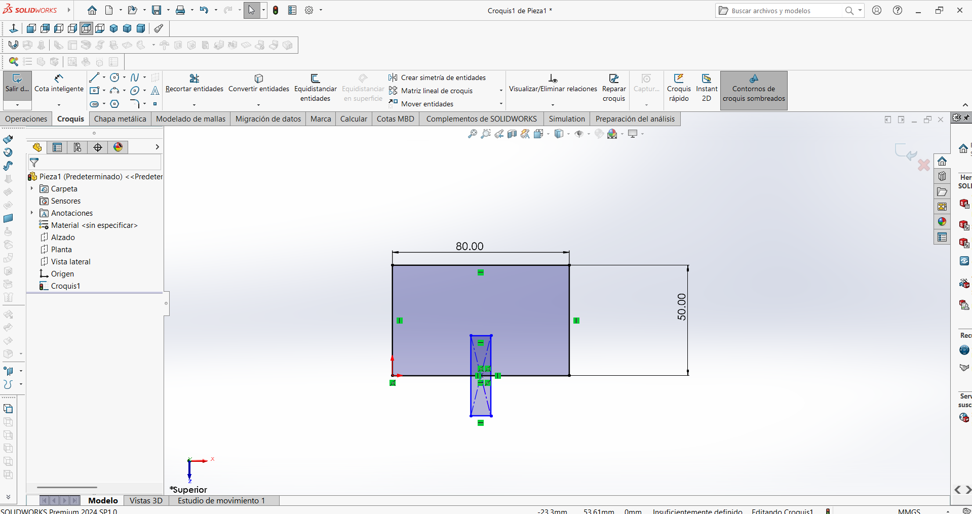
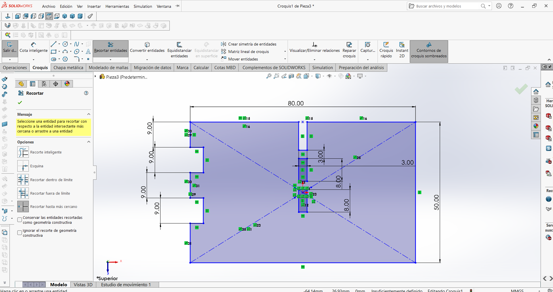
STEP 2: The cut was designed so that it could fit with another part during machining. In this step, the dimensions were assigned.
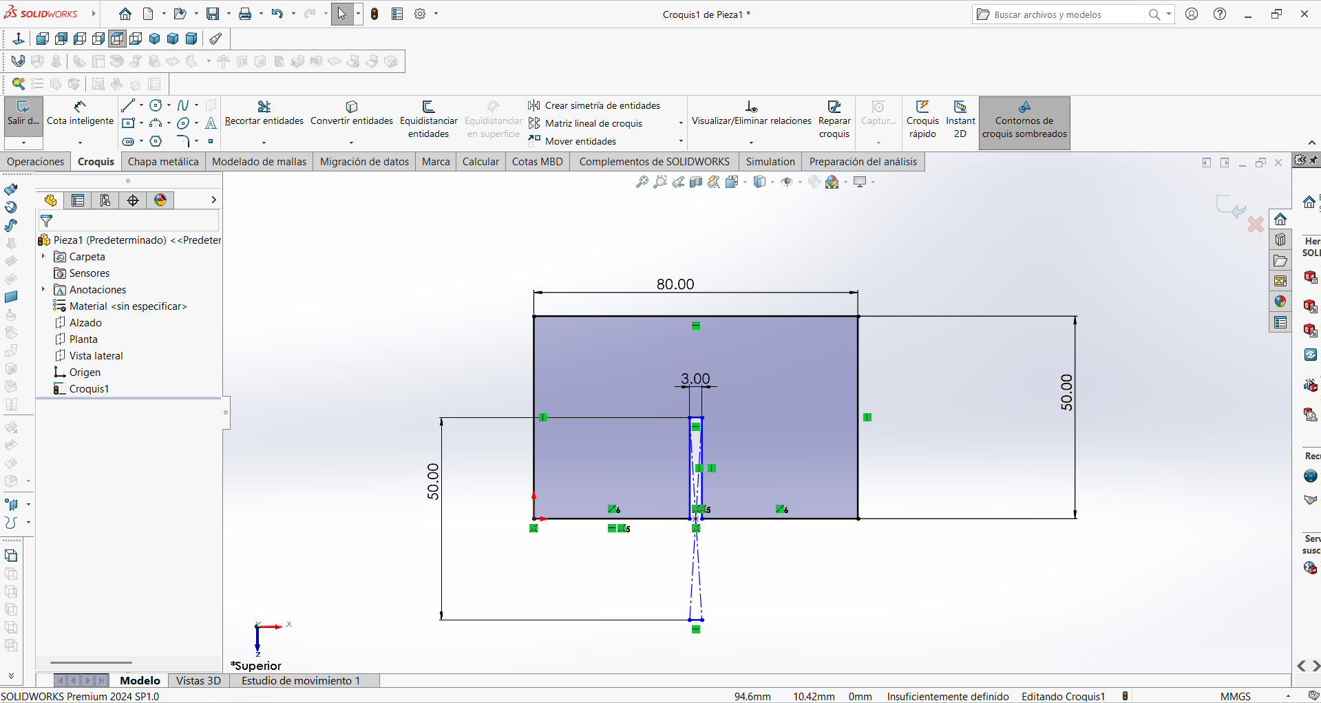
STEP 3: The excess material was cut off so that it would not be recognized as a sequence when transferred to the CNC cutting software.
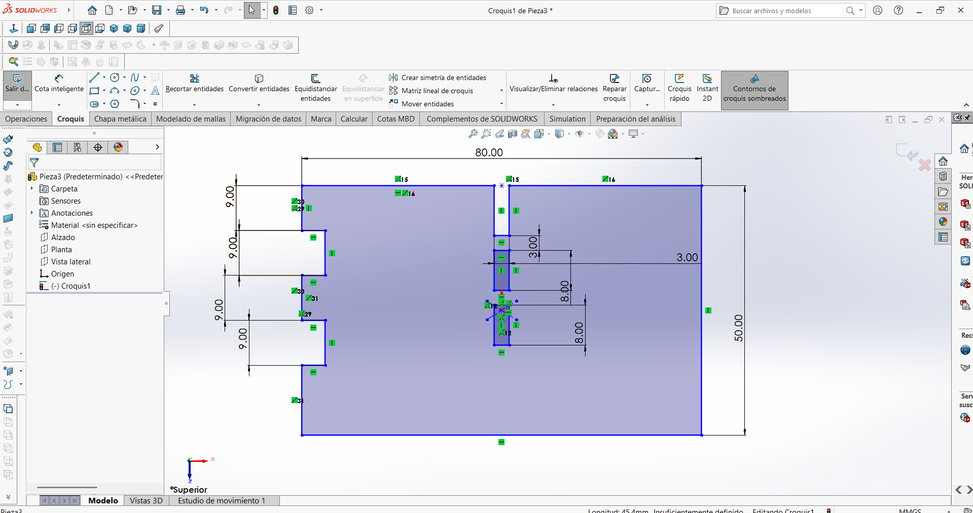
STEP 4: The first design was obtained, which now includes all its dimensions, and the elements we didn't need were eliminated.
Design piece 2
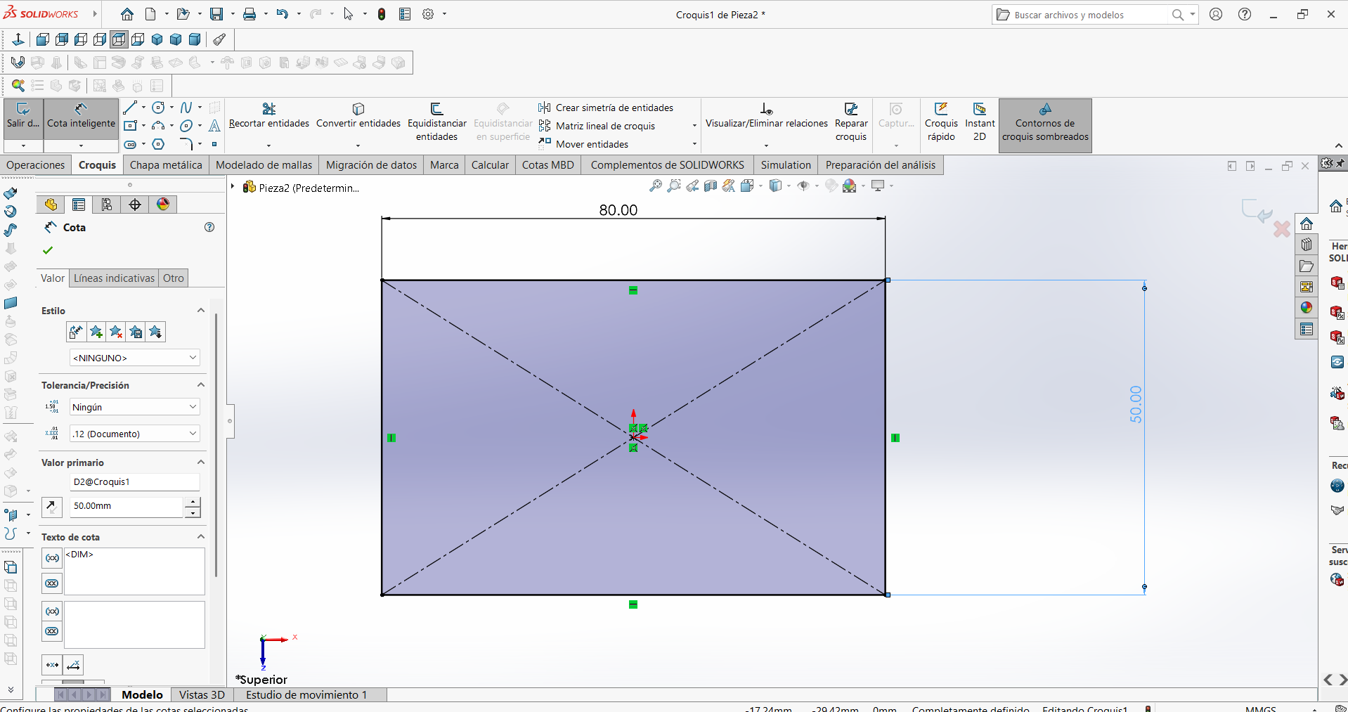
STEP 1: The initial rectangular design was completed so that the dimensions could be added with the corresponding measurements.
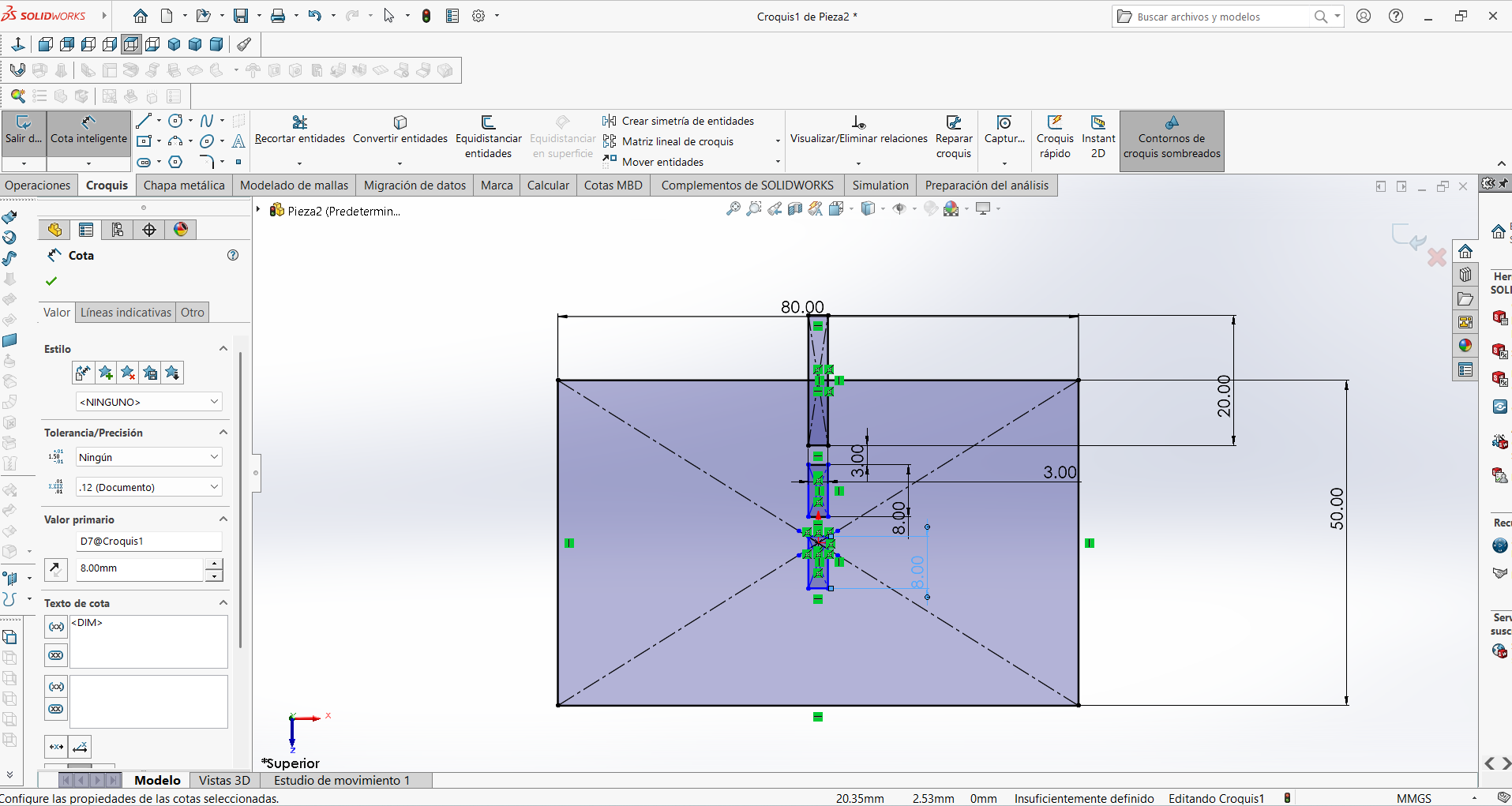
STEP 2: The connectors were designed so that the pieces fit together exactly. In this step, the designs were made with rectangular shapes.
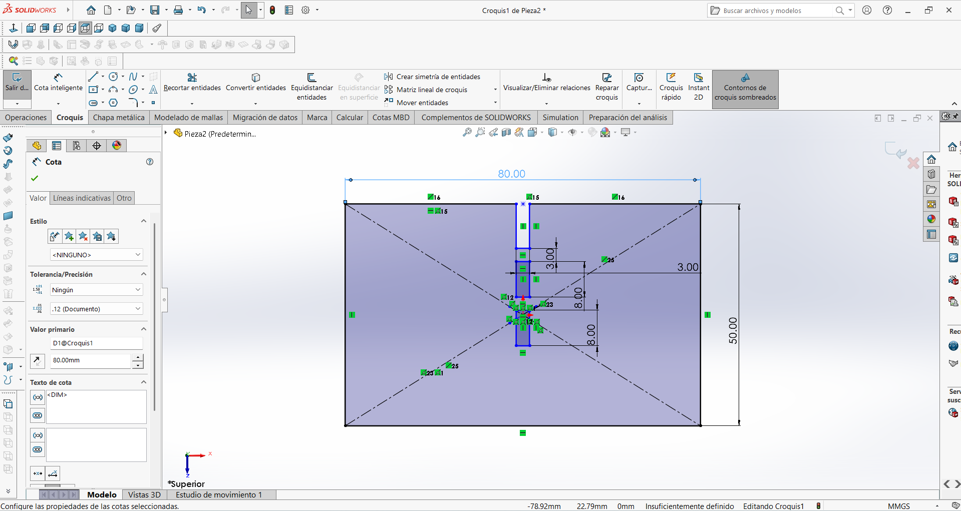
STEP 3: Excess parts and auxiliary lines that were not necessary were eliminated so that there would be no errors when exported.
Design piece 3
STEP 1: Part 2 was used as a template because the design for the side connectors was generated in this step.
STEP 2: The auxiliary lines were removed so that the cut lines could be clearly seen when exporting.
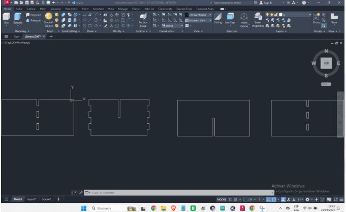
Importing the design into VCarve Pro
To perform the cutting on the UCCI-owned CNC router and with the support of Alexis, I will be using VCarve Pro, a software that provides a good solution for cutting parts on a CNC milling machine, including large pieces larger than 24" x 24". It includes tools for 2D design and 2D and 2.5D toolpath calculation, along with the ability to import and plot toolpaths from a single 3D model (STL, OBJ, etc.).
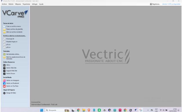
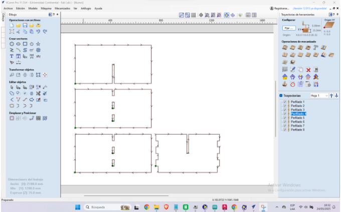
VCarve Pro work environment
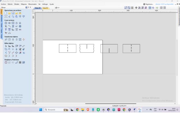
The next step is to view the imported image
Defining CAM Toolpaths
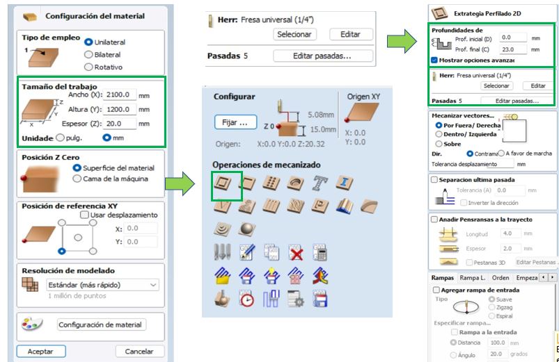
After importing the SolidWorks-generated DXF file into Vectric VCarve Pro, I began by setting the material dimensions, including the thickness of the MDF used. I then adjusted the position of the design on the workspace to optimize material usage.
Next, I generated the CAM toolpaths needed for CNC machining. To cut the outer contours of the parts, such as the sides, shelves, and base of the shelf, I used a 2D Profile Toolpath, with the cut configured along the outside of the vector. I selected a 1/4" (6.35 mm) endmill, with a total depth of cut of 15 mm, divided into 5 mm passes for greater safety and control.
I opened the DXF file in Vectric VCarve Pro. I adjusted the material size (thickness, length and width) based on the part to be machined.

Here we can modify the design in terms of dimensions and shapes. In the profile toolpath, we configure the tool type; in this case, we choose the 1/4" (6.35 mm) universal cutter with two cutting edges.
The spindle speed is set to 17,000 RPM, the feed rate to 1270 mm/min, and the penetration rate to 432 mm/min. These settings are suitable for machining softwood, as they allow for clean, efficient cuts
without compromising the integrity of the material or the tool.
Material setup is an essential step when preparing CAM toolpaths, as it defines how the material is positioned and worked within the CNC work area, in this case we have set the dimensions on the x, y and z axis, establishing (2100.0mm in x, 1200.0mm in (y) and 20.0mm in z)
We also set the starting depth and the depth of cut. The starting depth is usually 0.0 mm, i.e., from the surface of the material. In the pass configuration, we've considered 5 passes. For this multi-pass strategy, VCarve automatically calculates the intermediate passes based on the tool's capacity.
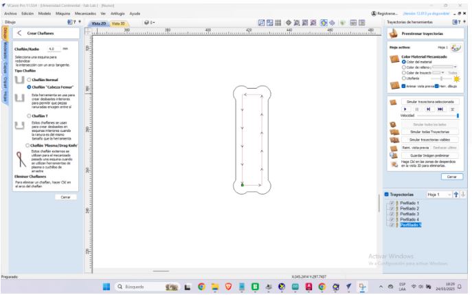
Union type
Adjustments are made for the type of union.
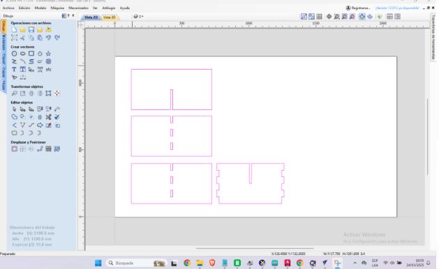
Final views of the design
Here are the final views of the 2D design.
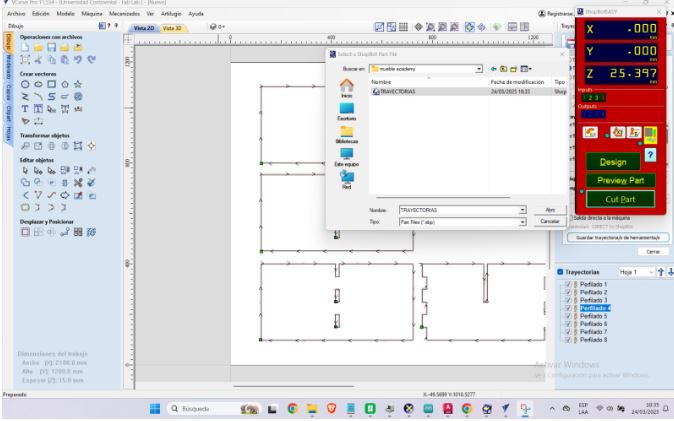
Next we can import the design into the CNC machine software ShopBot Control Software.
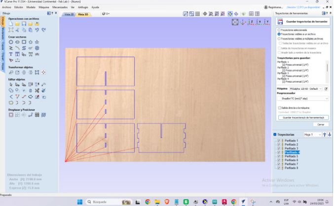
3D View of the Material
Once the toolpaths are configured, we can open the 3D view in VCarve Pro. The view allows us to simulate and visualize how the cutting paths will appear on the material before sending them to the CNC machine. It displays an accurate visual representation of the result, including:
- Cutting depths
- Internal and external contours
- Details of slots, engravings, and pockets
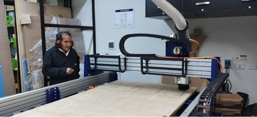
Machining Process
To carry out this work, I chose as a base material a pressed wood board measuring 1.5 mm thick and 1.40 x 2.40 m. I placed and fixed this board on the work table of a CNC router from the SHOP BOT brand.
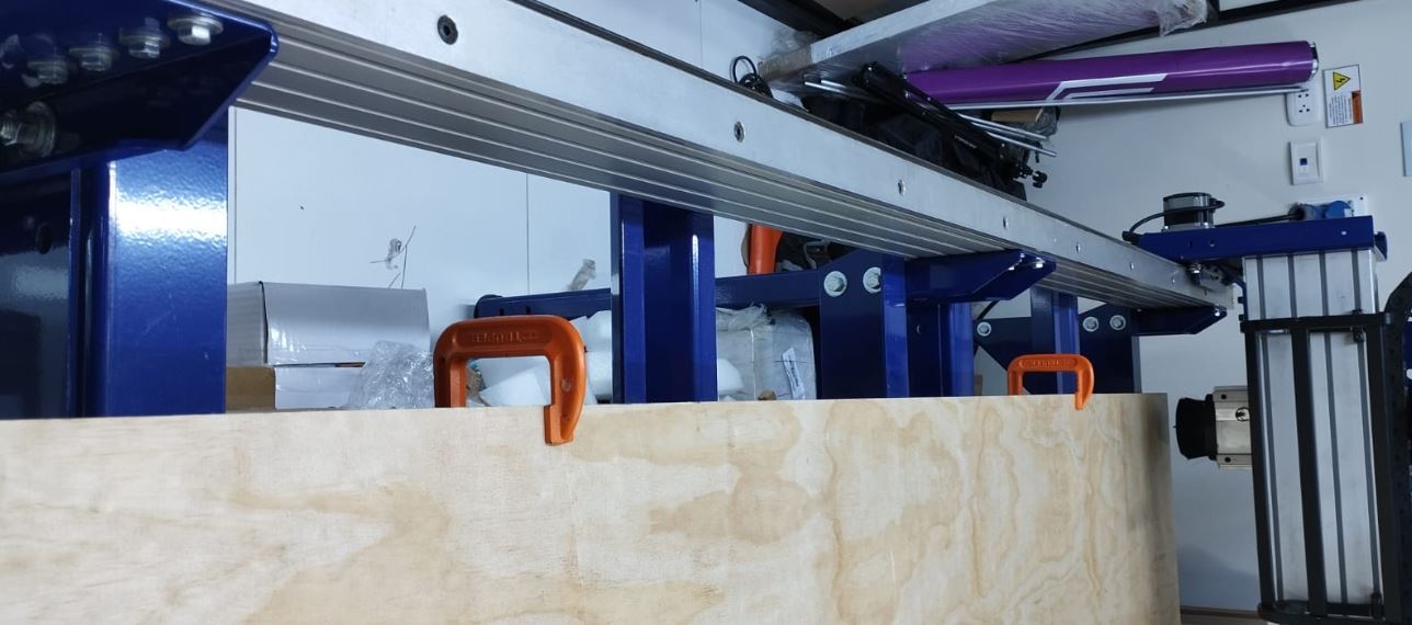
The wooden board is then fixed and held. For this, 04 screw-type fasteners were used.
CNC Machine Control
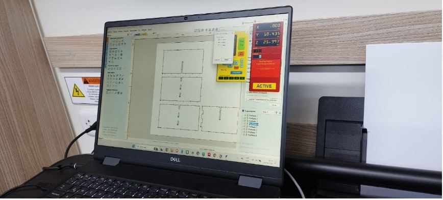
The next step is to set the coordinates of the worktable and the CNC machine control.
The CNC starts the routing and cutting movement
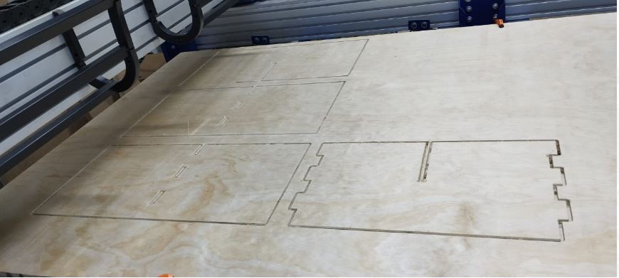
The CNC finishes cutting the design
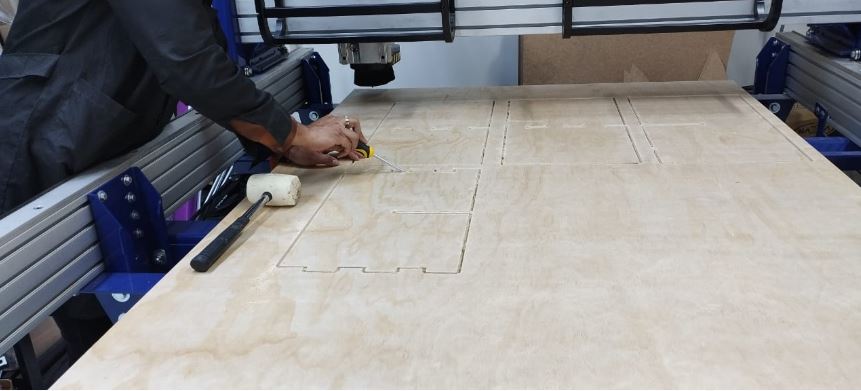
Proceeding to extract the cut plates using tools such as a screwdriver and a crowbar and carefully without damaging the contours.
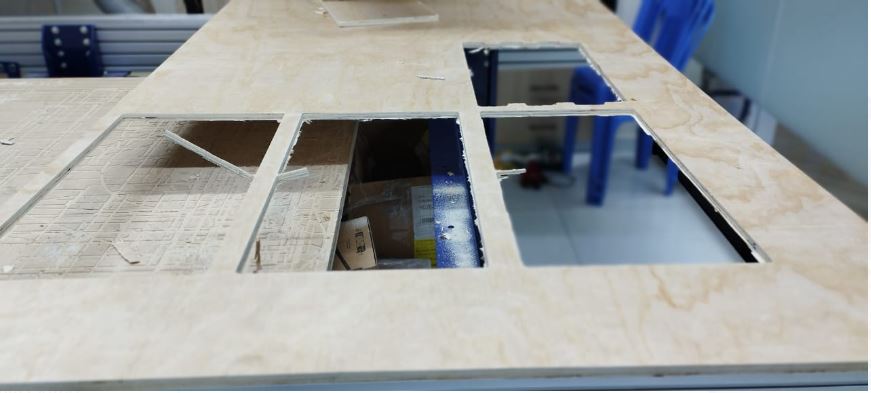
View of the plate after the plate cuts have been removed
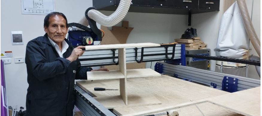
View of the assembled furniture using the fixing joints.
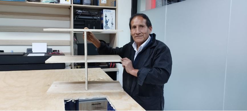
Another view of the finished piece of furniture
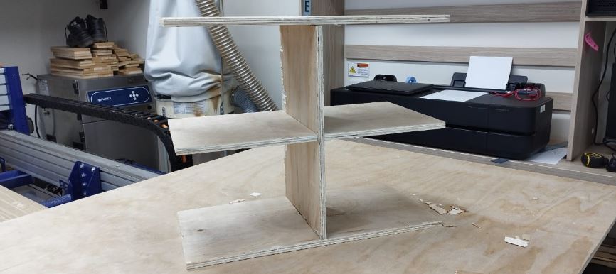
Stand for decorations
Stand to place various decorations

Did you have any problems?
During CNC machining of the softwood with a 1.5mm cutter, a somewhat worn tool was used. This resulted in some inaccurate cuts, increased friction, and burn marks and chips on some edges. Therefore, work was stopped, the cutter was replaced with a new, sharp cutter, and the cutting parameters were adjusted: the depth per pass was reduced to 0.4mm and the feed rate was lowered to 500mm/min. Machining continued with clean and precise results.
Link to files used this week
1.-router design.zip