Week 7: Computer Controlled Machining
Group Assignment (link): 1) do your lab's safety training 2) test runout, alignment, fixturing, speeds, feeds, materials, and toolpaths for your machine
Individual Assignment: make (design+mill+assemble) something big (~meter-scale) extra credit: don't use fasteners or glue and include curved surfaces
Group Assignment & Introduction to our CNC
CNC stands for Computer Numerical Control. A CNC machine is a type of machine that can cut different material according to specific computational directions given to it by a computer program. Technically, both laser cutters and 3D printers may be considered as CNC machines as well since they also operated and move according to numerical controls determined by software. Less formally, CNC machines generally refer to machines that are larger and cutting wood or other materials with drill bits.
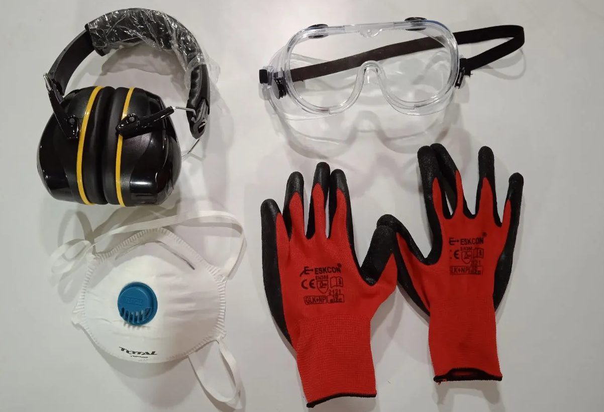
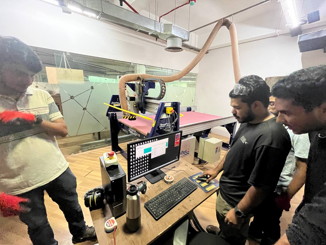
Safety! At the very beginning we went through a rigourous safety training, which makes sense because these are very powerful machines that could cause serious problems if handled negligently. Even before entering the room with our CNC we were given and required to wear the proper personal protective equipment (PPE):
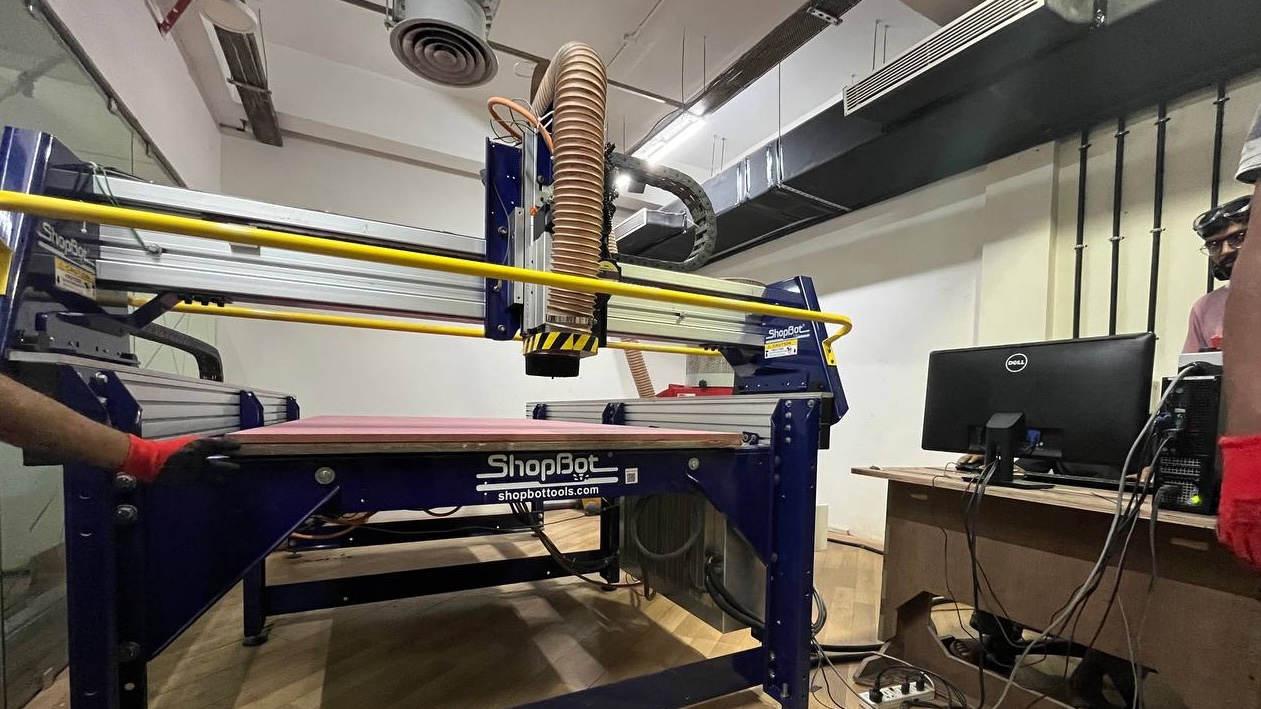
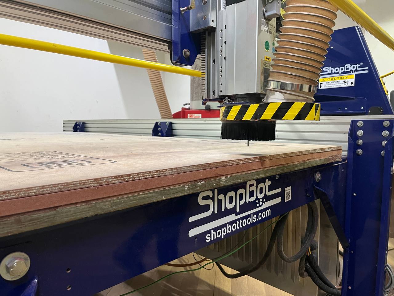
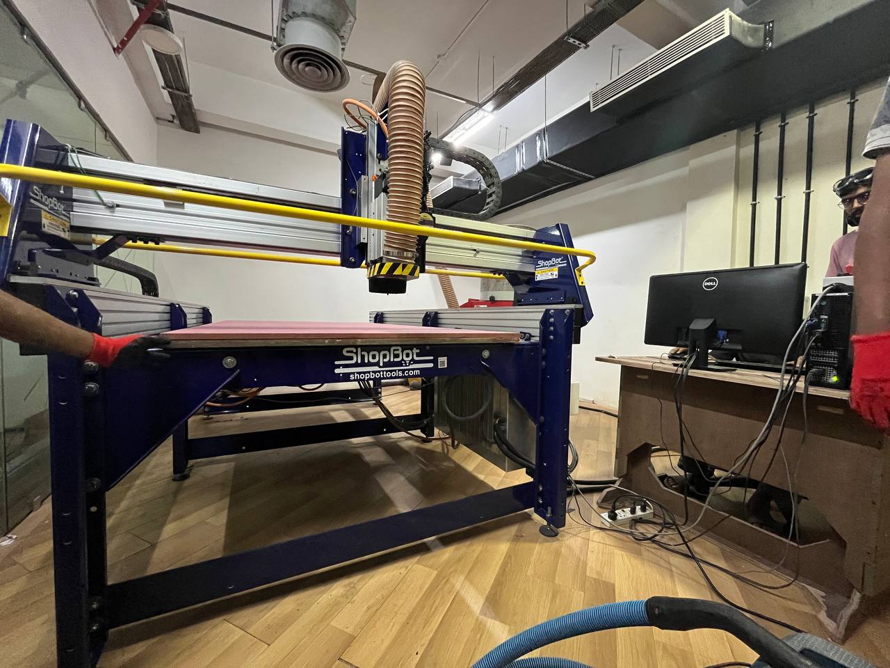
Once we had adorned our PPE, we entered the room where is the CNC. Here is the large machine (with computer). It's called a Shop Bot.
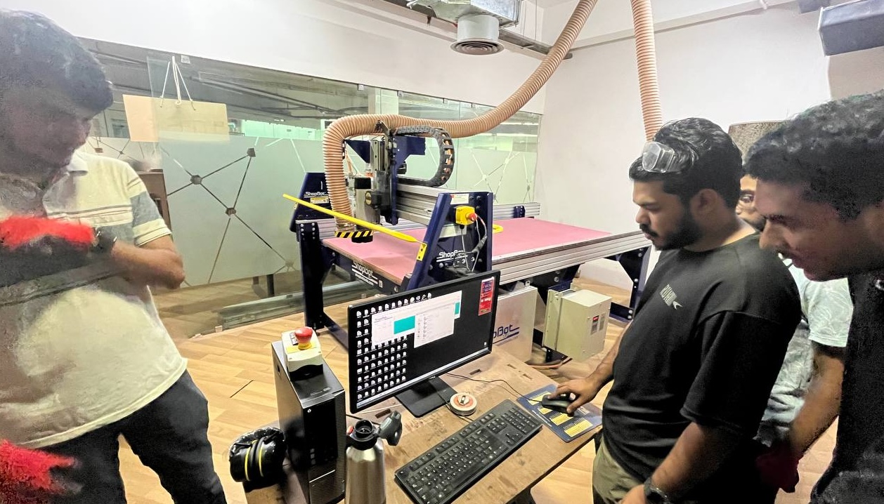
Here's another view also showing the computer with software. Behind the computer are three switches, to control the power for: 1) The machine movement in 3 directions, 2) The spindle, which holds the bit which cuts the material, 3) The vacuum or dust collector.
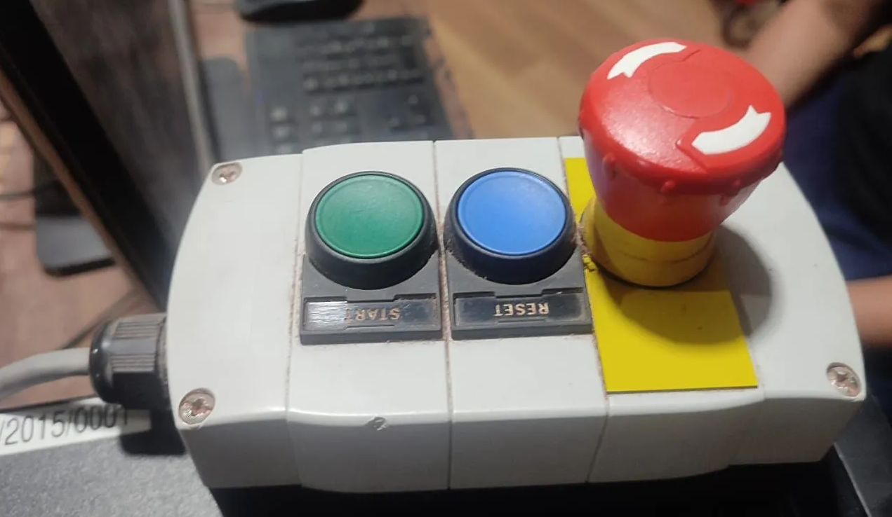
Safety! To the left of the computer are some big buttons for start, restart, and an emergency stop button.
Here's a close-up of the head, with key parts labeled. Also we note here that the board to be cut is atop another board called the sacrificial layer.
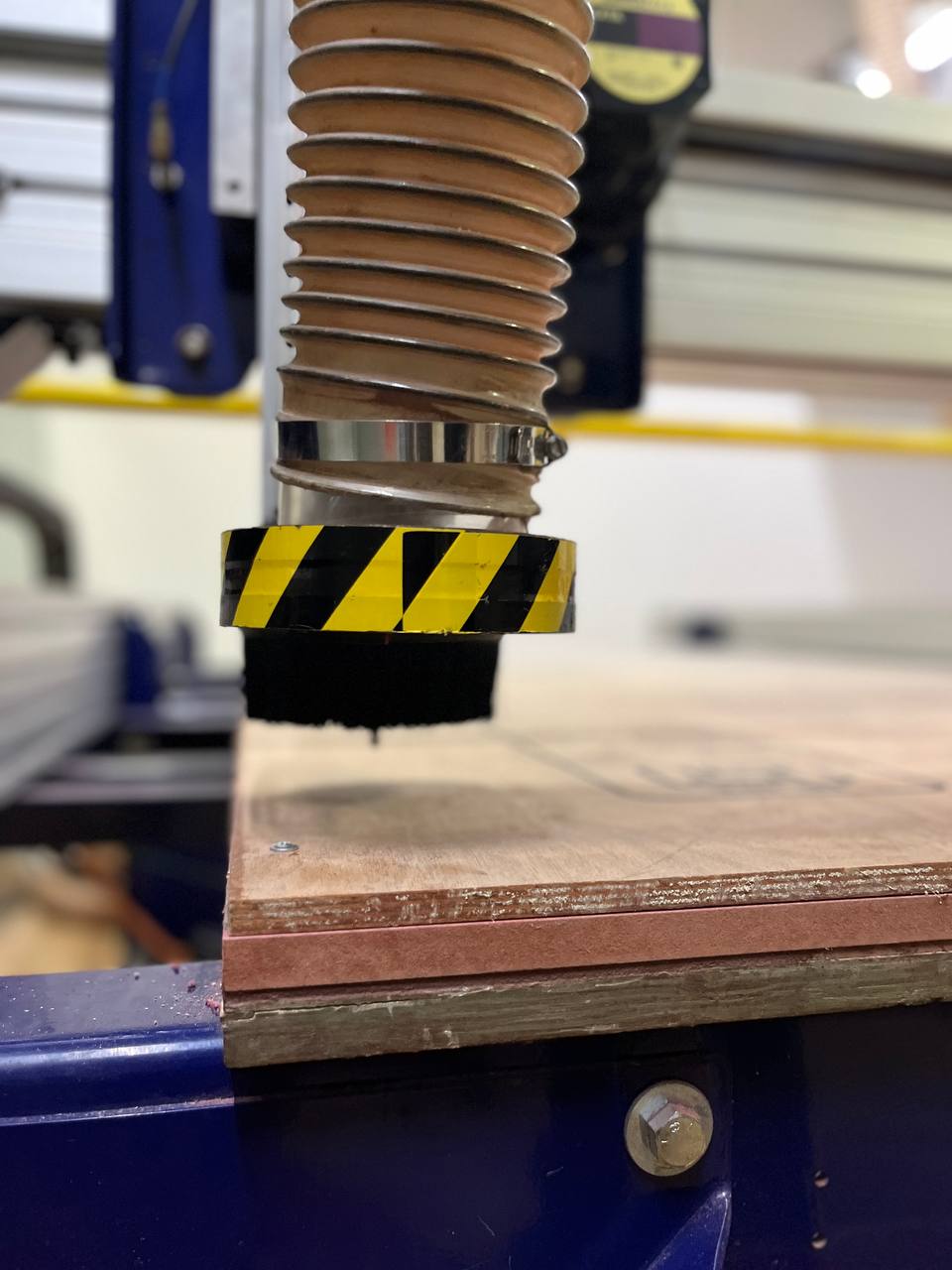
Before cutting it's common practice to screw the board to the sacrificial layer and calibrate in all 3 directions, positioning the spindle with bit in the corner, and to make an air rectangle around the border to ensure that the bit doesn't go over the screws.
Full information on operating procedure can be found on the group assignment page.
Project Design
Back to Fusion 360...
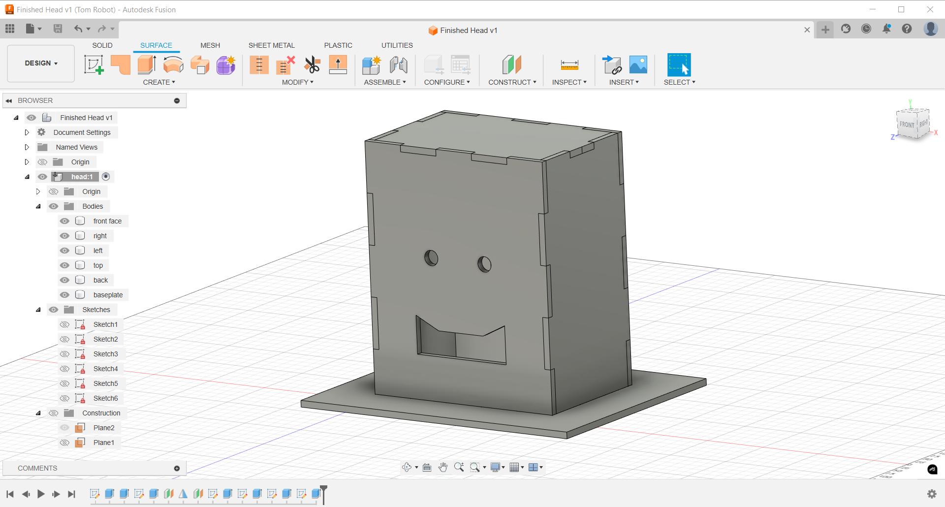
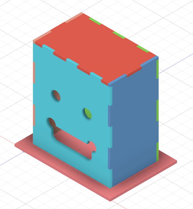
Here is first draft of my project, which is also related to my final project:
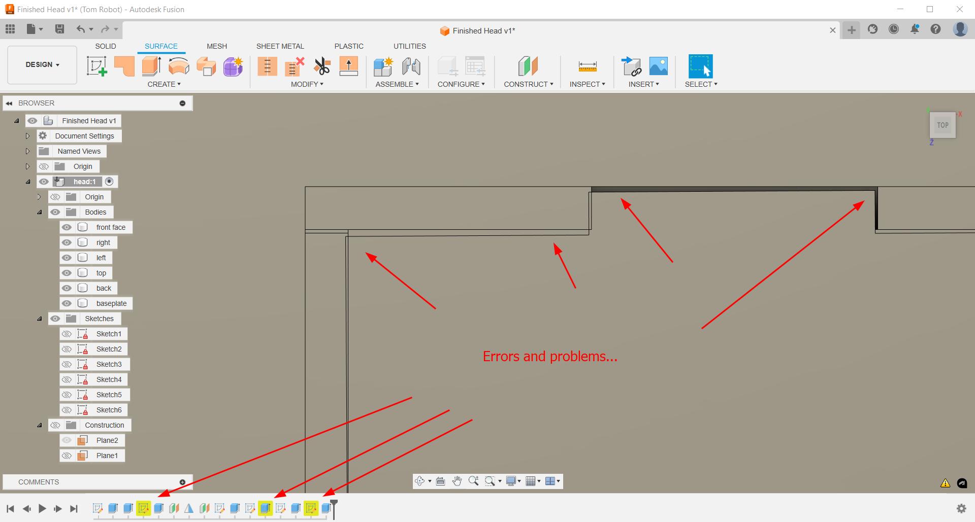
Only problem is that parameter for thickness doesn't work well:
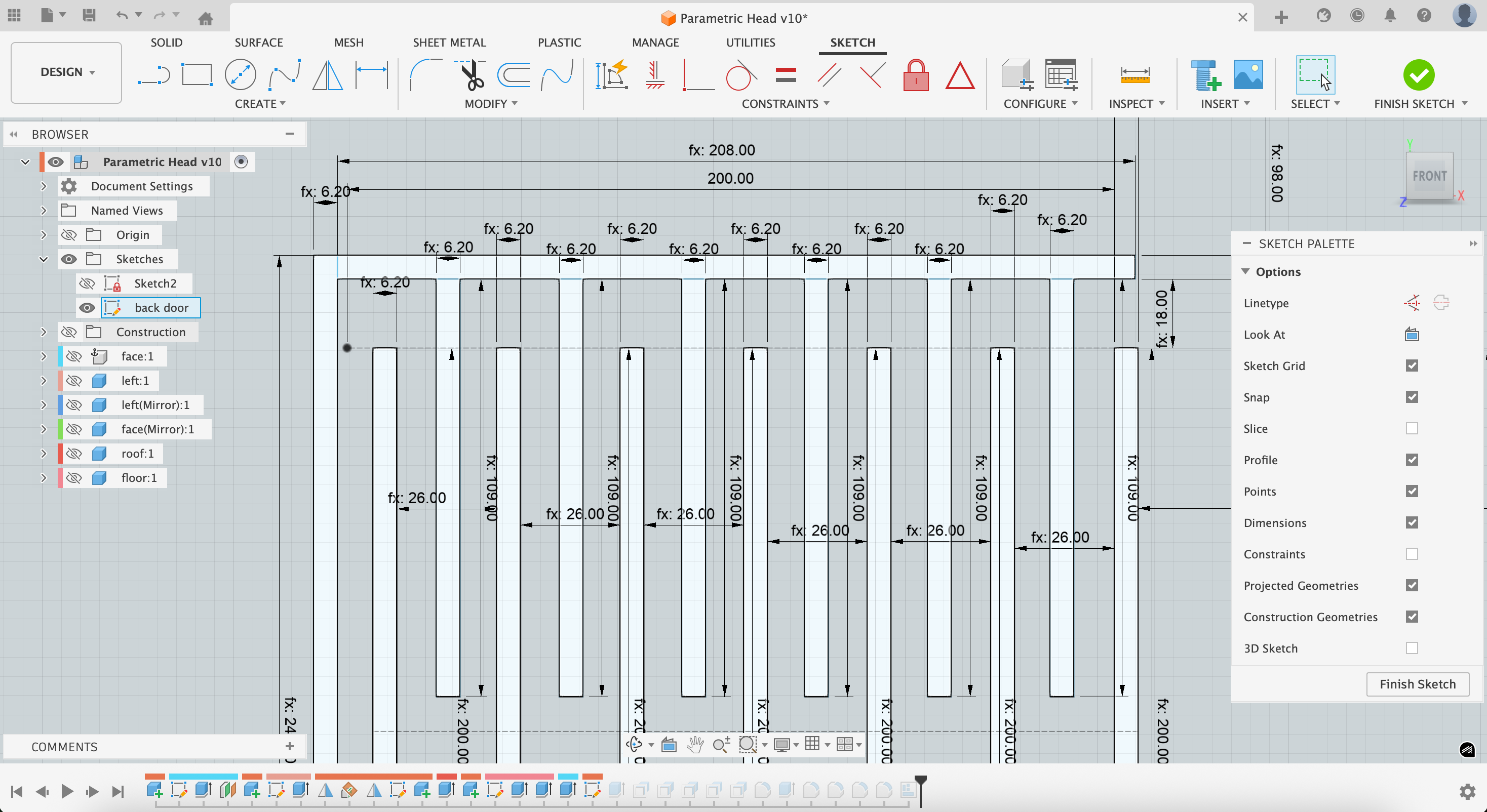
So I went back and did the project again. This time I was very careful with the parameters from the beginning:
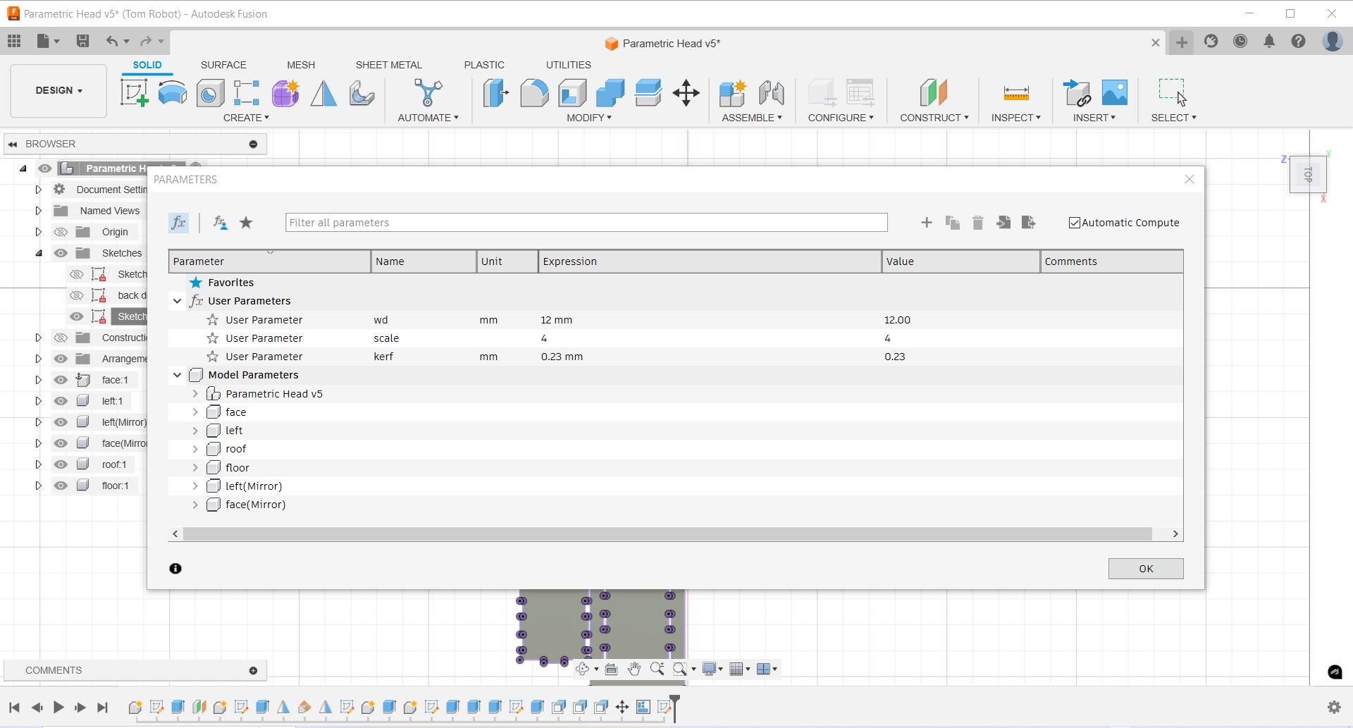
All the measurements defined in terms of parameters and all sketches constrained:
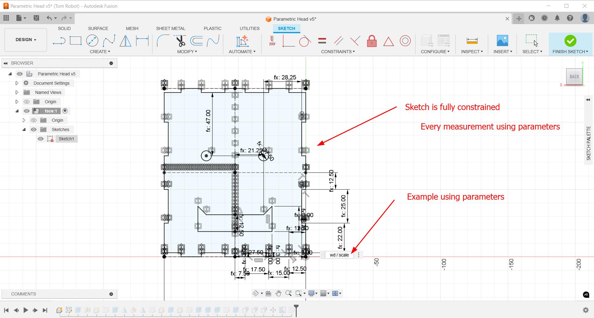
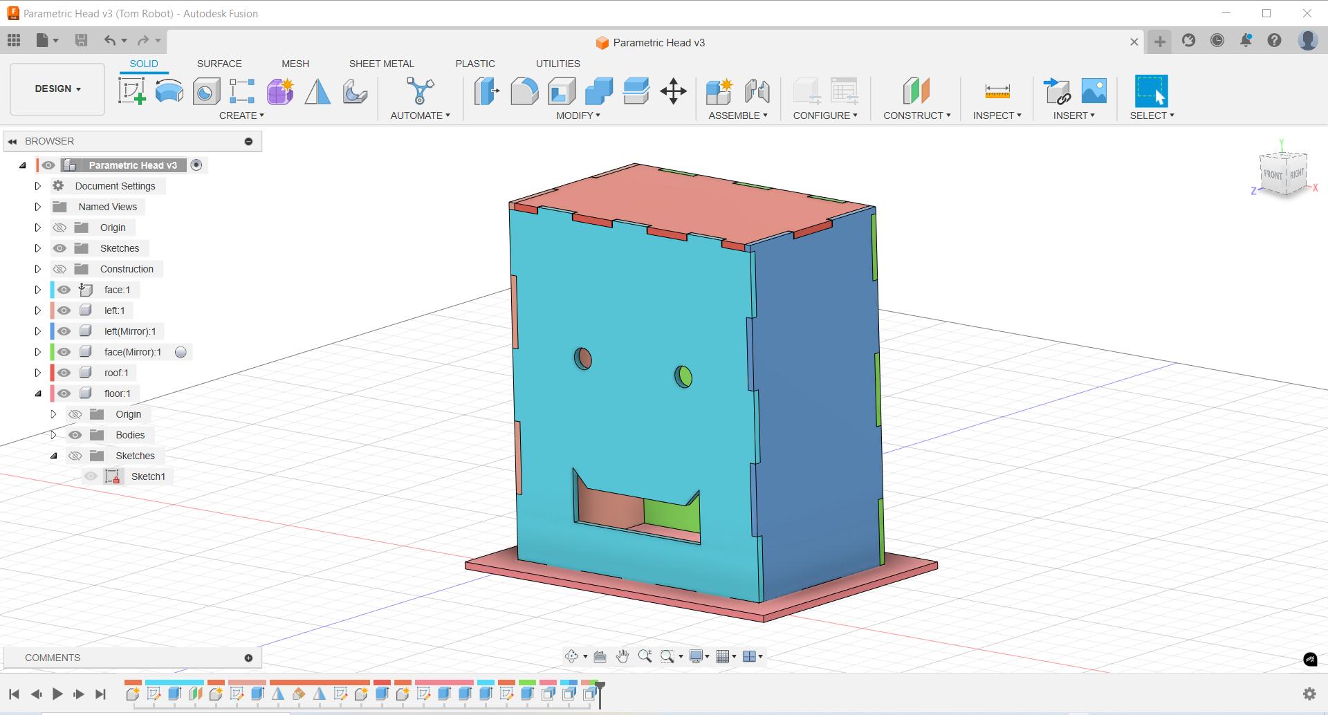
Here is the final version. I can change any parameters and nothing bad happens.
Arrange and Export
Now it's time to export. First we must arrange the components in 2D. Navigate to Modify->Arrange
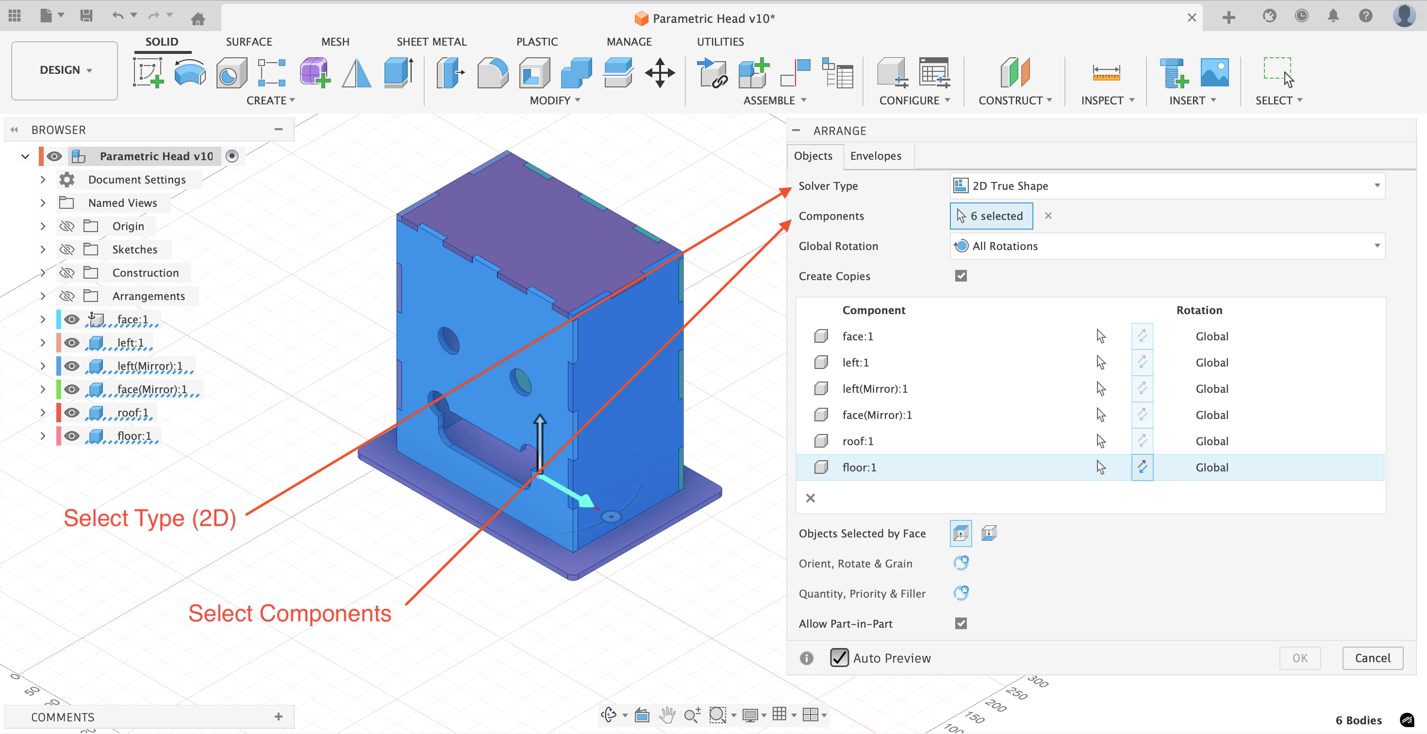
In the second tab, specify the appropriate parameters of the envelope, the 2D space within which the items will be arranged. As we will be using a 6 mm bit, then we leave a spacing of 15 mm (6+6+3), 6 for each side plus an additional 3 mm as a buffer.
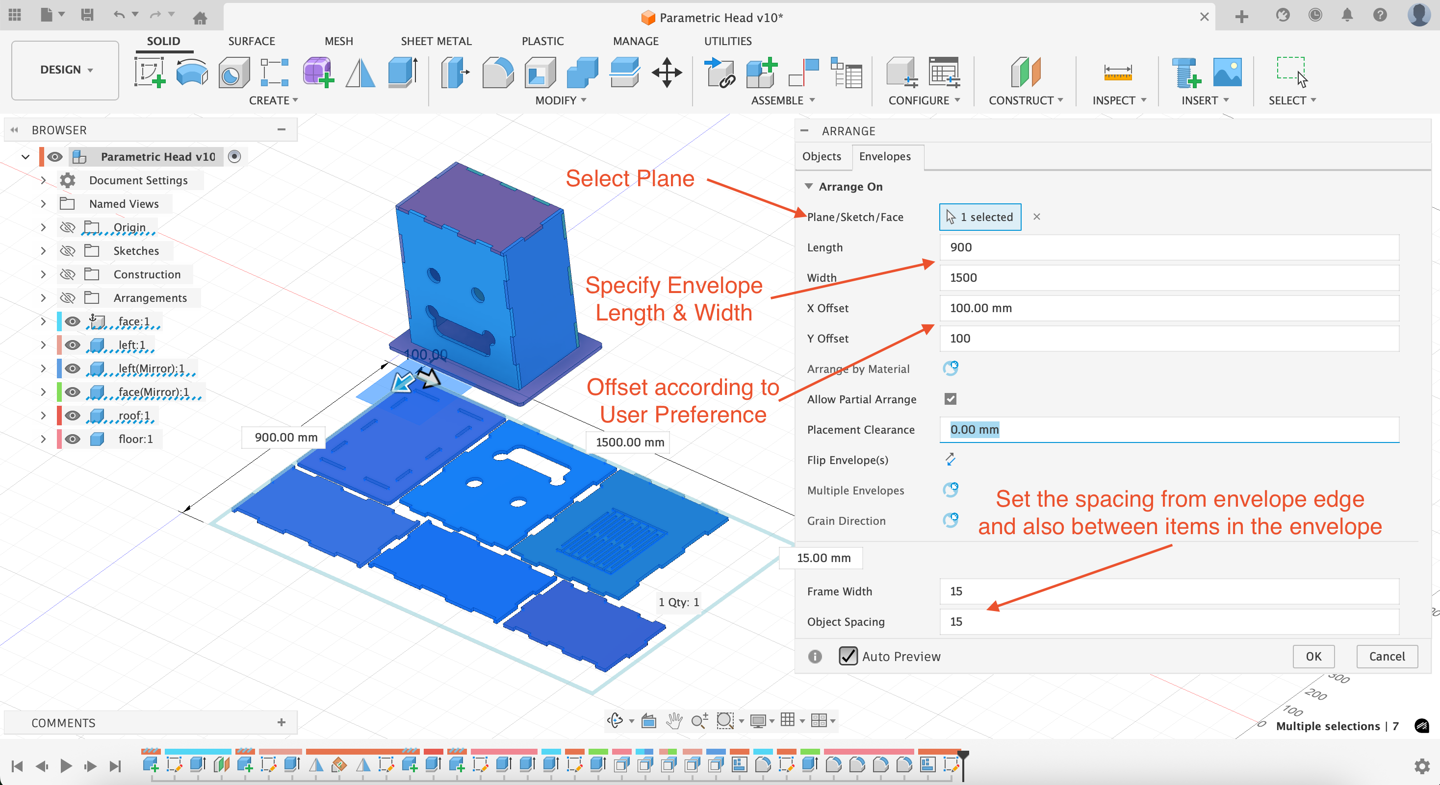
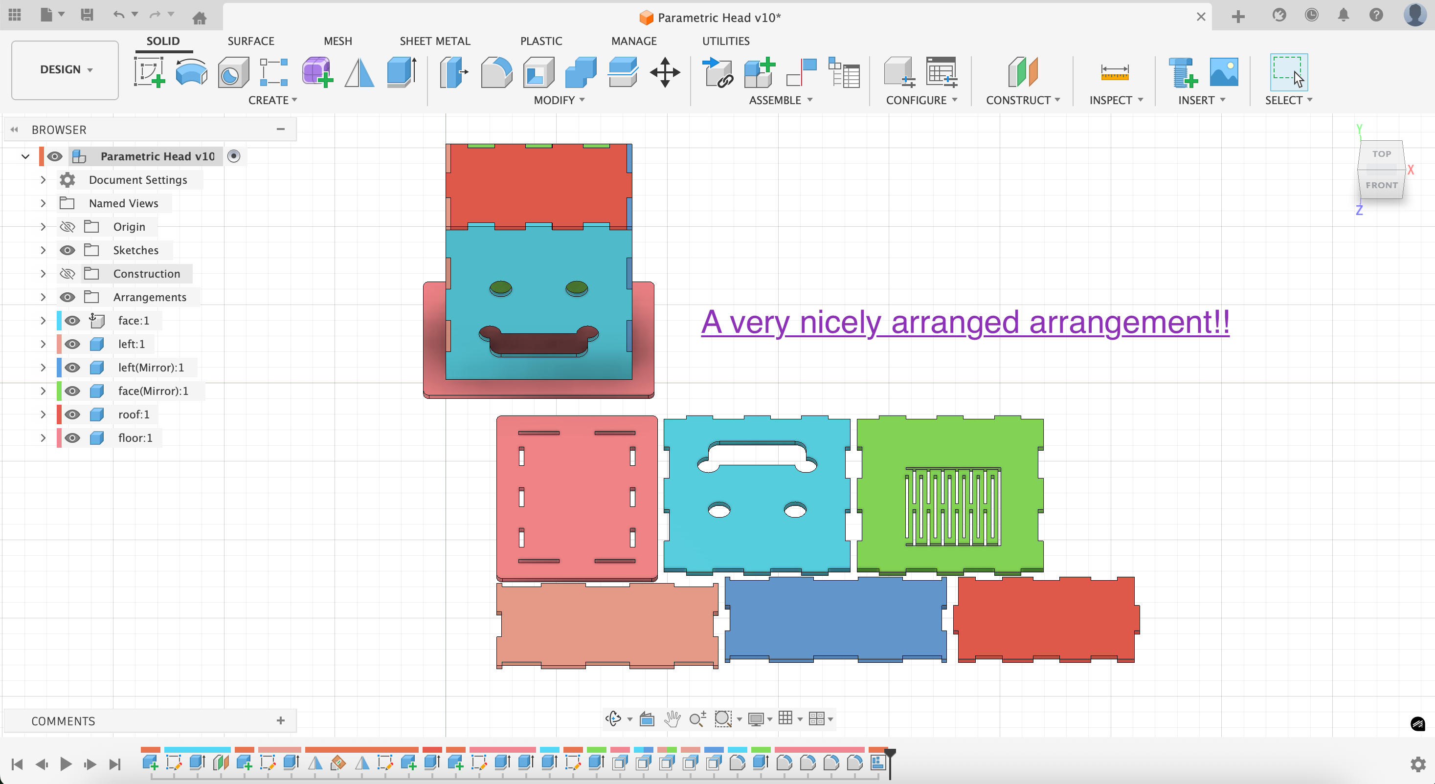
Finally we have this nice result!
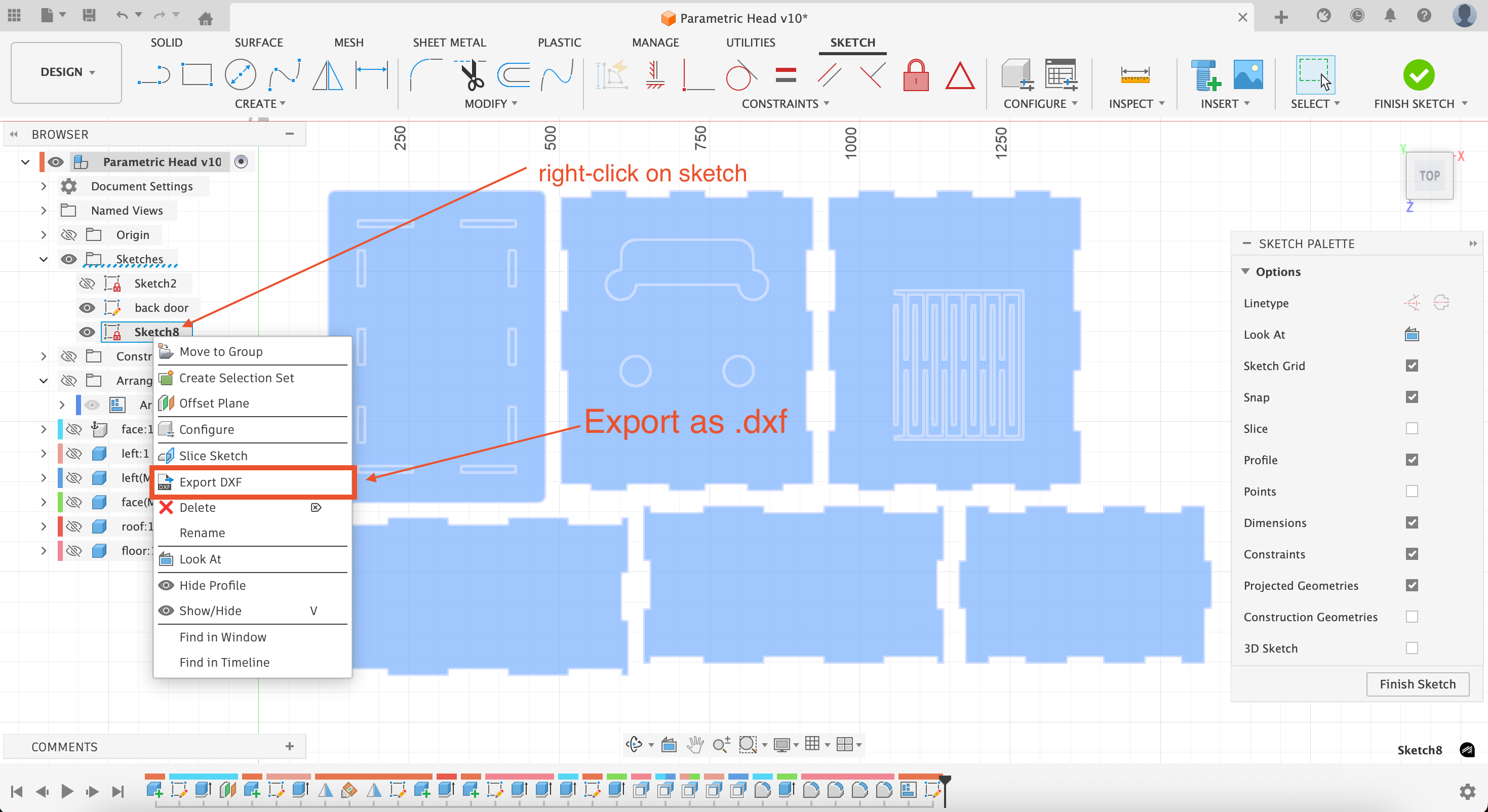
Next we'd like to export the 2D arrangement in .dxf format. To accomplish this, we first create a sketch and project the arrangement onto that sketch; only then we can export as shown below:
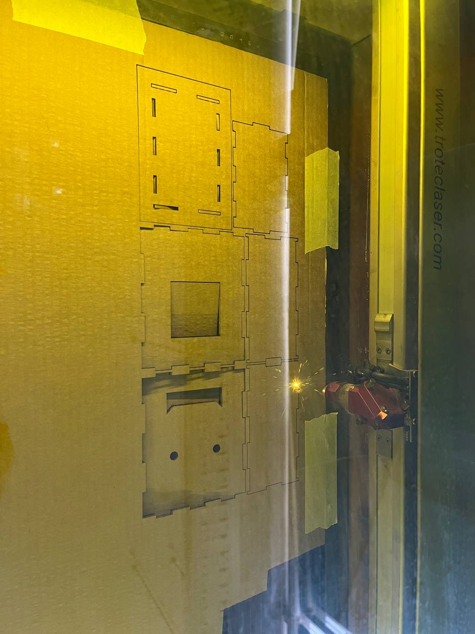
Laser-Cut Test
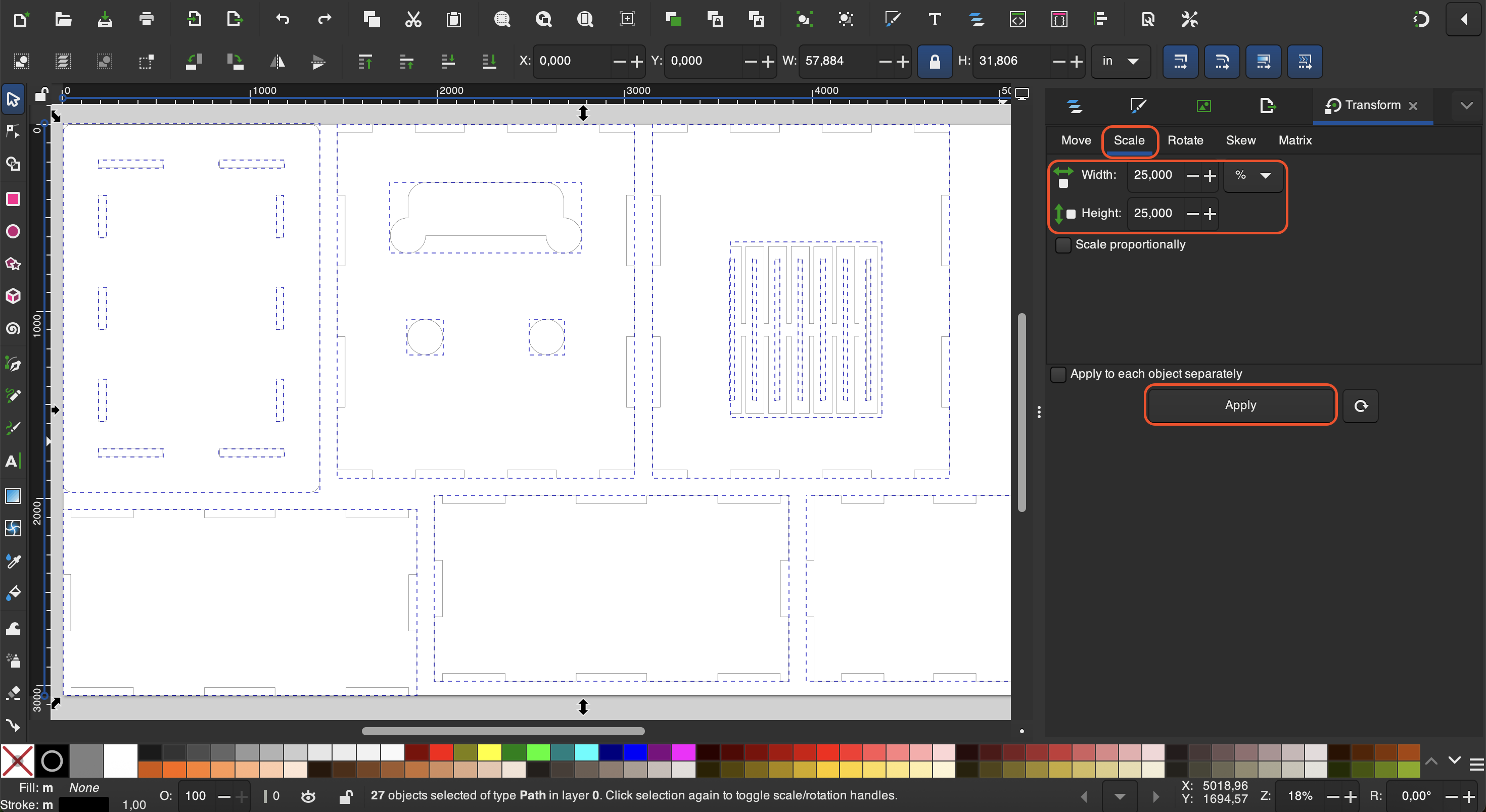
Before producing in large scale, we will cut with the laser cutter; in case of issues, we just lose a short time and a bit of cardboard. Now obviously when we cut with cardboard, we'll be cutting a scaled-down smaller version. We already know that the width of the board we will use on the CNC is about 11.3 mm, and we also measured the cardboard to be 2.85 mm, hence a ratio of 2.85/11.3 is conveniently 25%. In Inkscape we navigate to "Object"->"Transform" to scale it.
Fortunately we already have good experience with the laser cutter from week 3, so we cut without any issue.
Here is the assembled model from cardboard. Actually it fits pretty well.
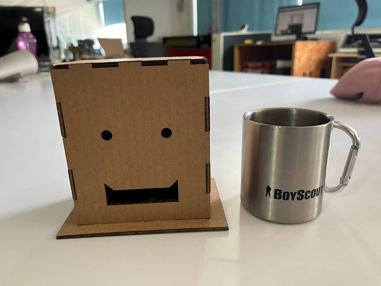
We do notice a few issues, so it was good that we first cut with the laser cutter.
- We forgot to include kerf on the vertical edges. Kerf need to be everywhere!
- The mouth is fine for laser-cutting, but for CNC will not be able to cut the sharp corners.
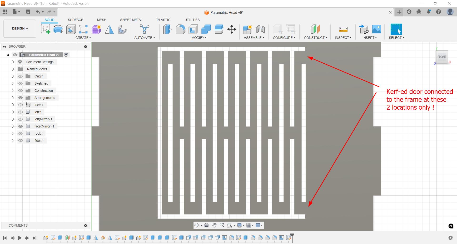
- The door on the back will be a problem.
Redesign & Kerf-Bending
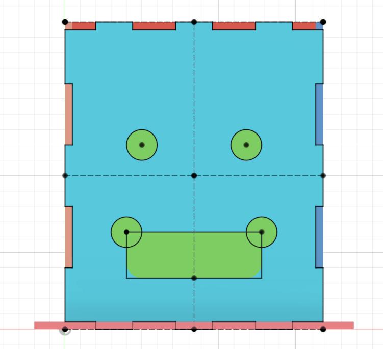
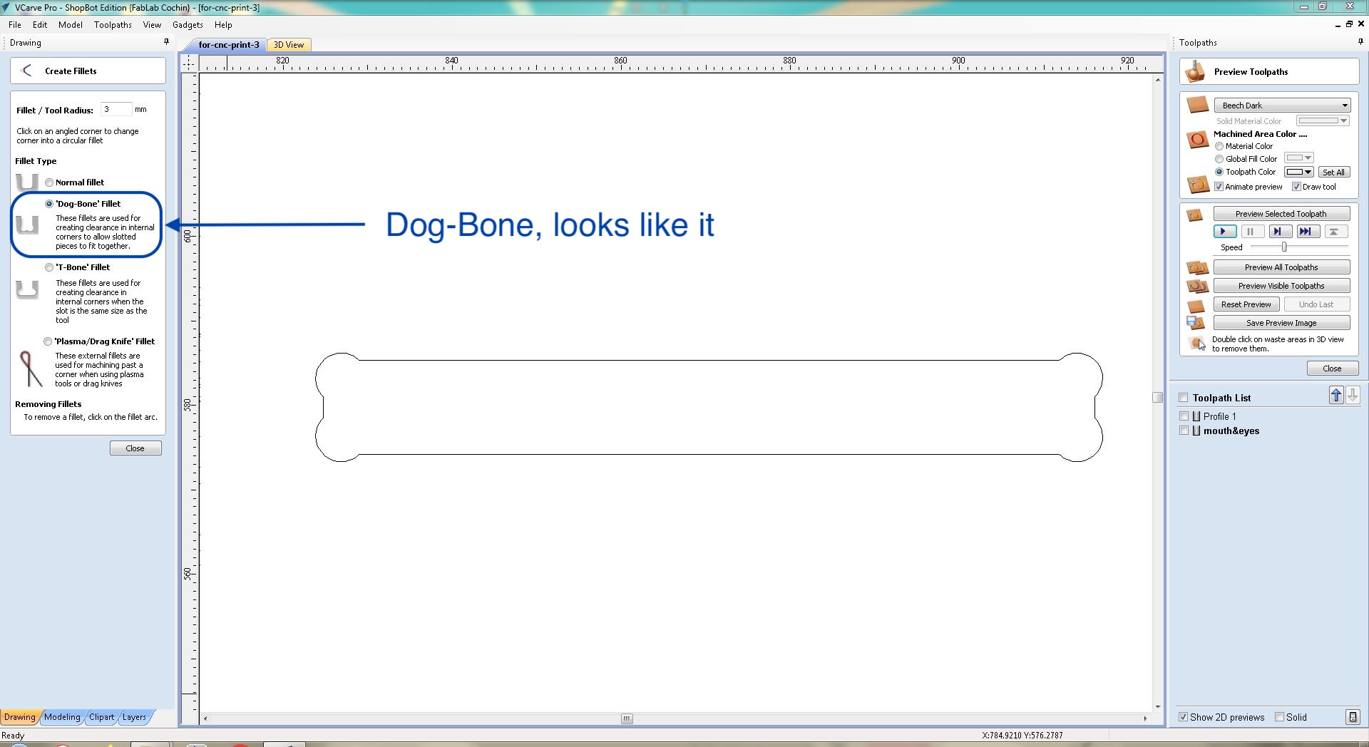
First we redesign the mouth. The top corners with circles, like an exaggerated dog-bone.
Next we consider to use kerf-bending to make the back door, as in the following example from Sreyas:
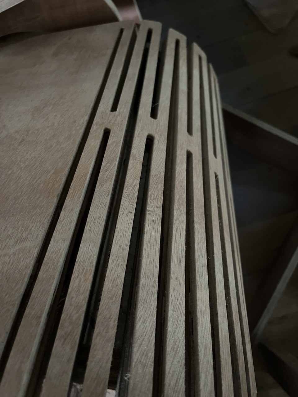
This kerf-bending technique cuts entirely through the wood, in contrast to some techniques that cut a groove 90% or so through the wood.
Here's the overall design, taken from examples in the lab:
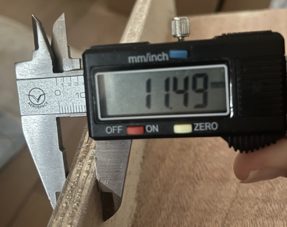
Here's the specific dimensions we used, also taken from examples in the lab. Fellows in the lab reported that with the thicker (18 mm) wood, it was still tough to bend it. For this reason I kept the same type of spacing because I knew that I'd be using a significantly thinner (11.3 mm) wood.
Finally, here is picture of how we measured the wood to get that measurement. Actually the wood was not uniformly thick, so we measured in about 10 places and took the average.
Preparation for CNC Cutting
First we'll open our .dxf file in the VCarve Pro Software, used in tandem with the Shop Bot. To start with, we will fix the job size and material (thickness).
Then with that being set we can move the project within the space, especially to keep it away from the edges if we've attached the board to the underlaying sacrifical layer with screws!
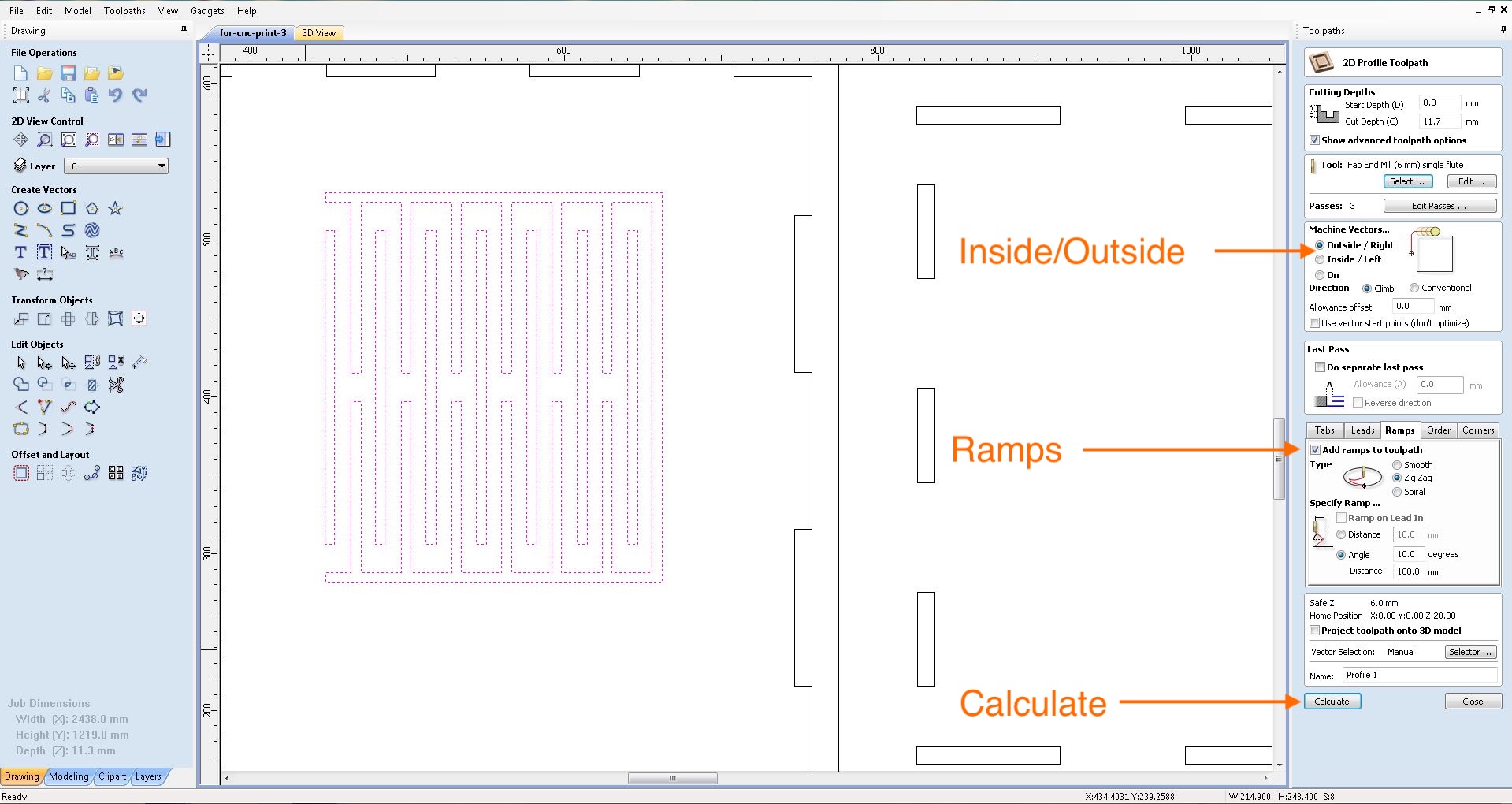
Then we'll go through each part of the job, specifying certain parameters like cut depth and tool, though these particular parameters tend to stay constant.
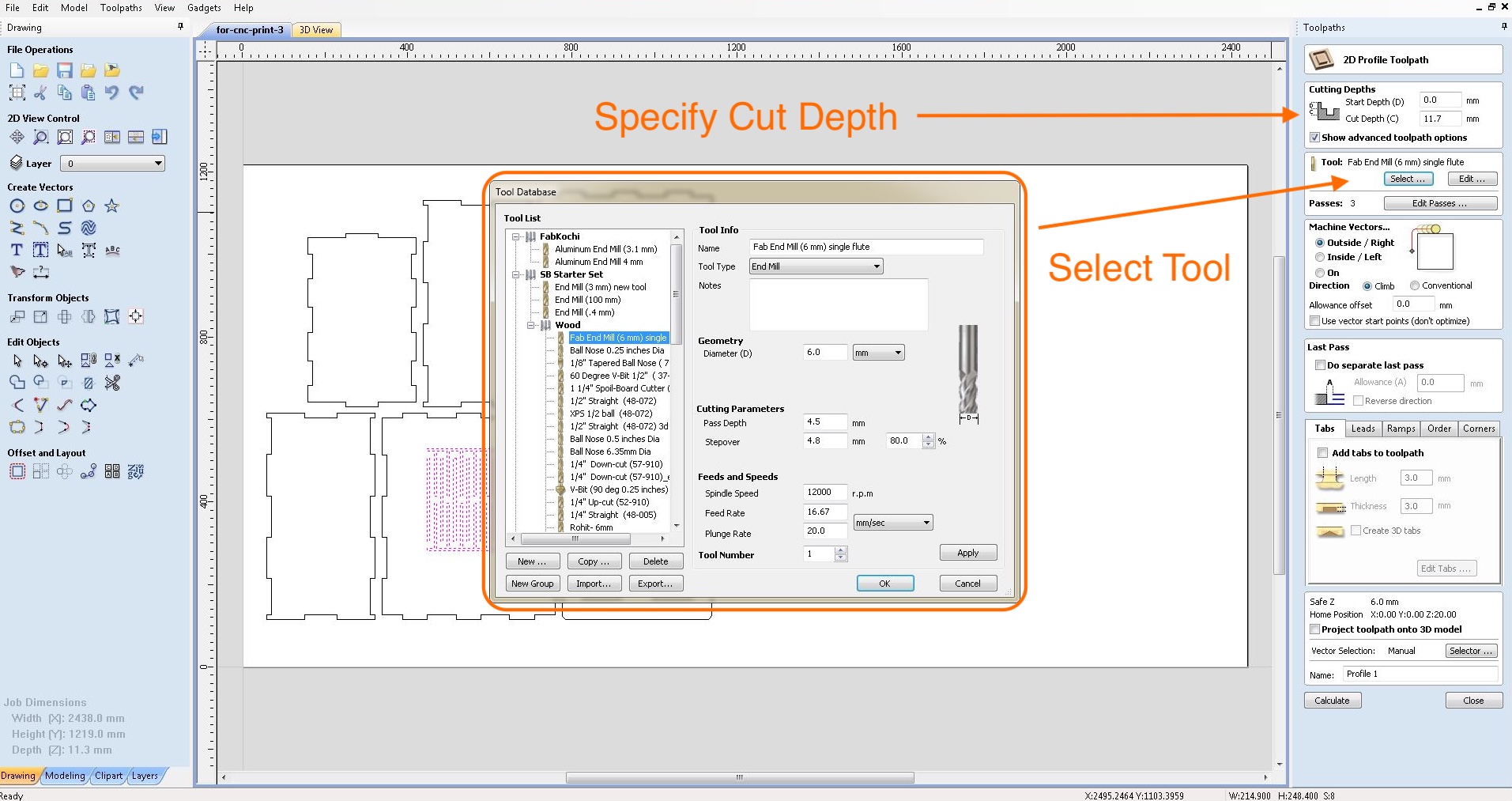
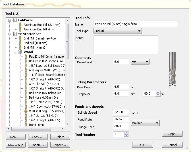
Lots of options for tools (drill bits), but we will use a 6mm single flute.
Some other important parameters are there, such as position of the drill bit inside or outside of the line and ramps. Here we have selected outside but it actually will need to be inside. The ramps are also important, as it is both difficult and dangerous for the bit to dig straight into so much material. Finally when this is done we can click on 'calculate', which will simply calculate the toolpath.
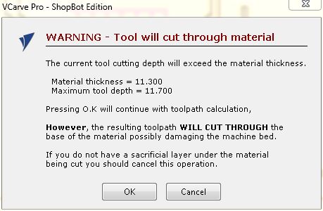
Here we get a warning because the cutting depth is greater than the material thickness, however this was actually intentional to make a clean cut completely through the wood. In fact we have the sacrificial layer underneath and we'll just be cutting into that a little bit (0.4 mm).
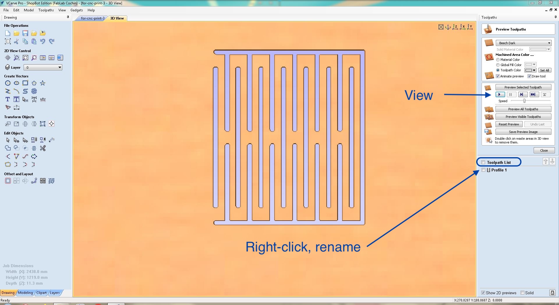
Now the first toolpath is complete. If we like we may both view it as well as rename it.
Then the next toolpath is for the slots on the bottom board. In this case we need to add "dog-bones" so that the tabs on the other pieces will fit in.
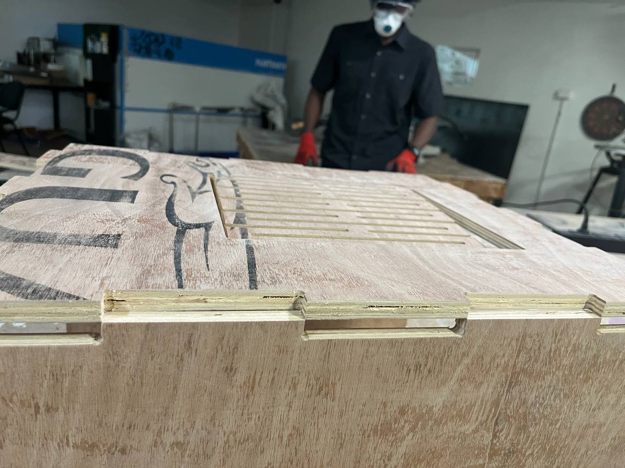
Then here is the final toolpath for the outline of the main pieces. Here we need to use tabs, which are small sections which are not cut by the tool, so that we have stability to allow proper cutting! We must select where to place tabs, and just 4-5 tabs for even a large piece are enough.
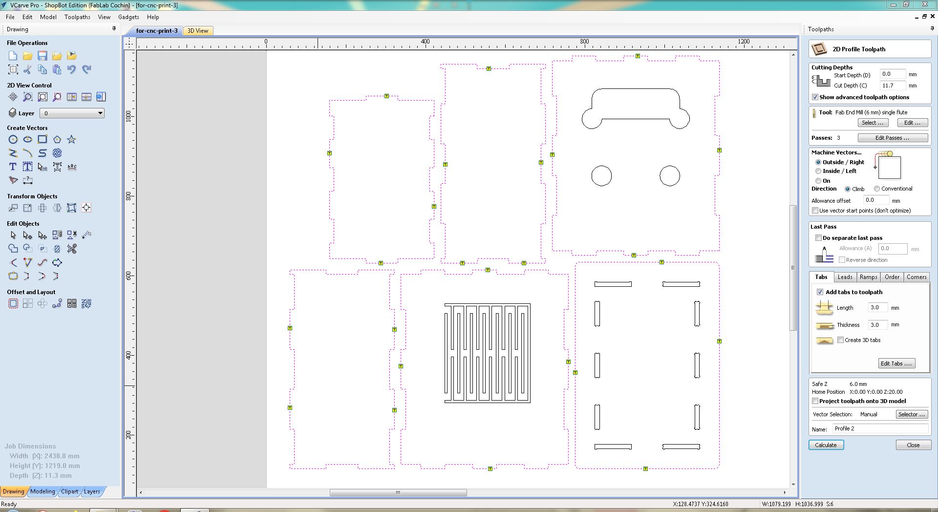
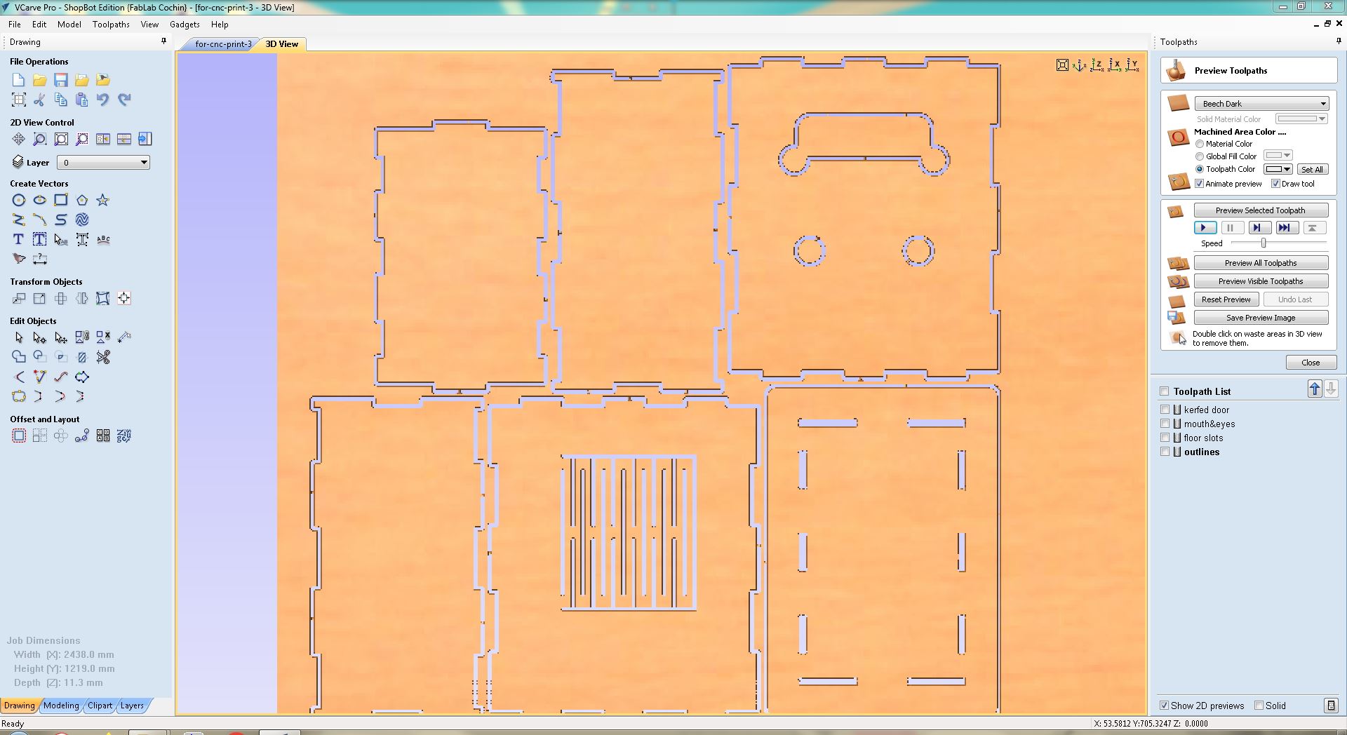
Then we can view the entire job in 3D. For us we have 4 different toolpaths with slightly differing parameters.
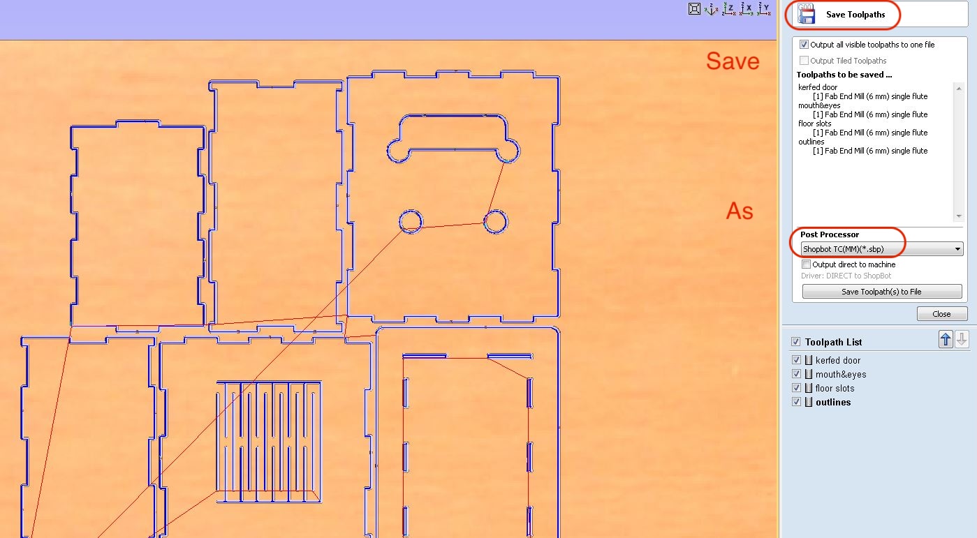
Finally we can save the toolpaths, it will be saved as filetype .sbp which is akin to G-Code for the Shop Bot.
Now we can enter the Shop Bot control system...
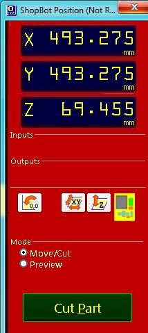
And start cutting!
Cutting, Sanding & Processing
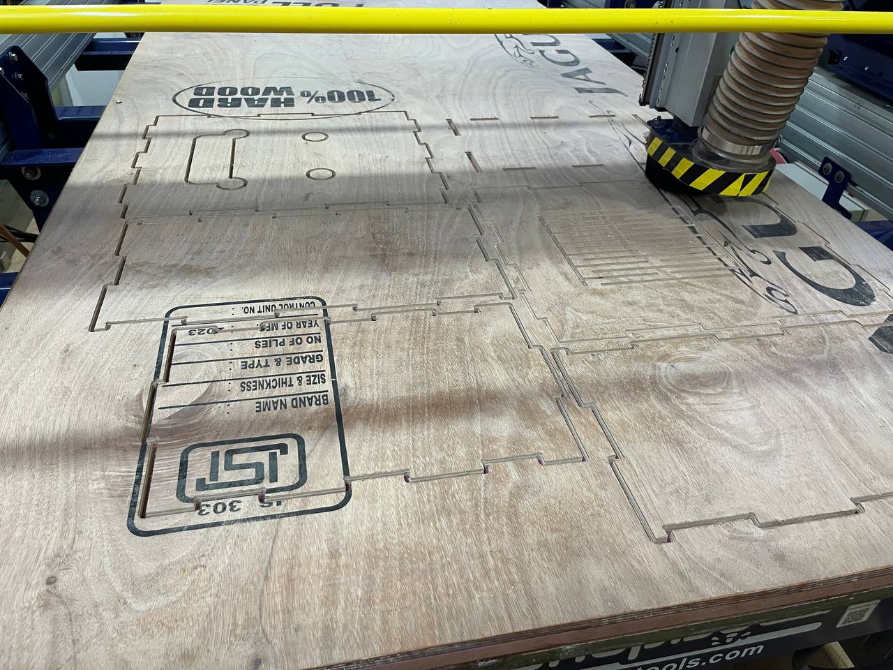
Here we see the nearly complete cutting process. The vacuum worked very well to clear the board from sawdust so we could see the result in real time.
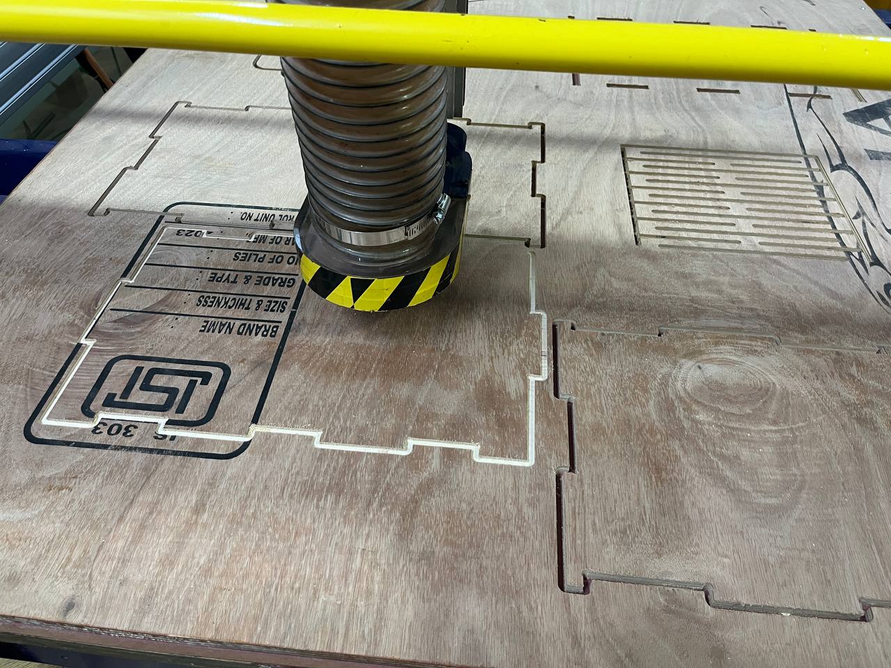
The endmill cutter actually passed through each part 3 times, each time deeper than before. In total it took nearly an hour.
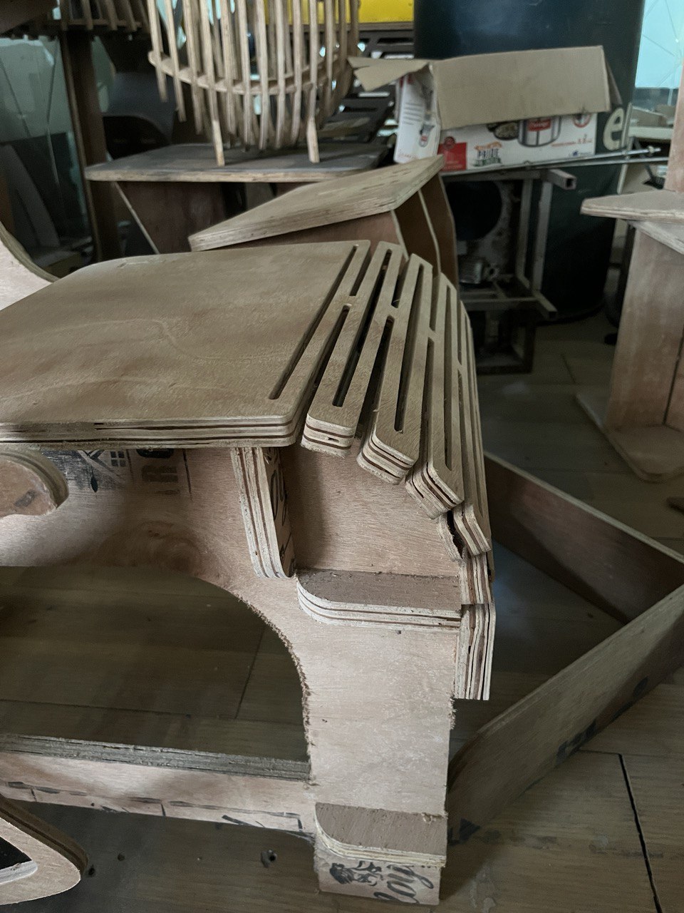
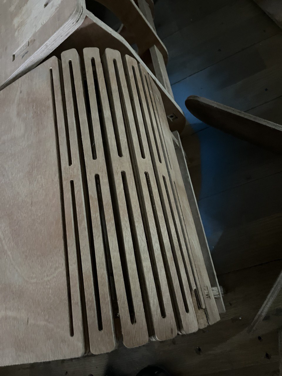
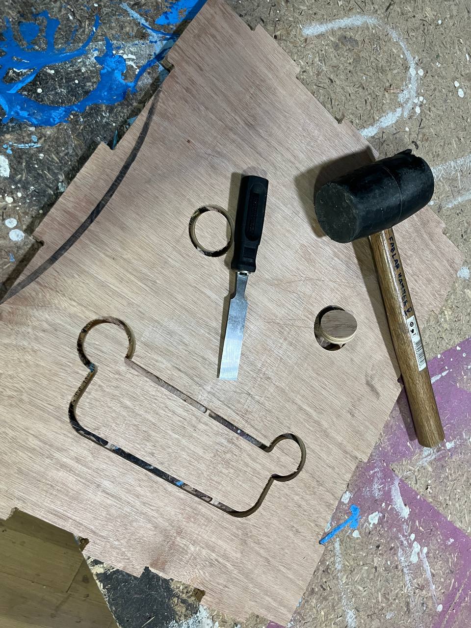
Cutting tabs: it was easier with the chisel and hammer than with the knife. But the tabs generally worked well.
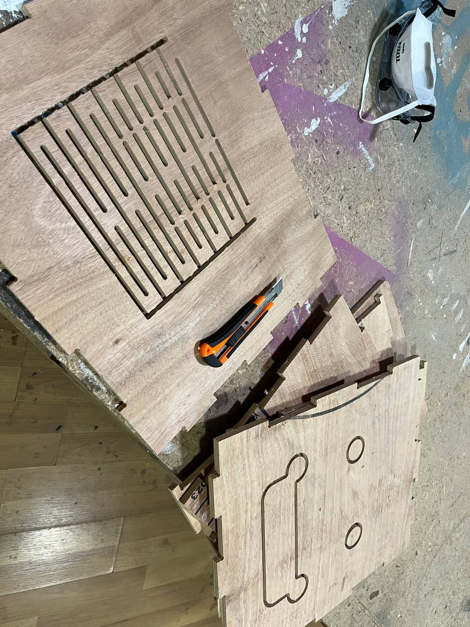
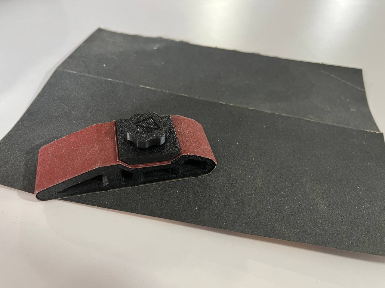
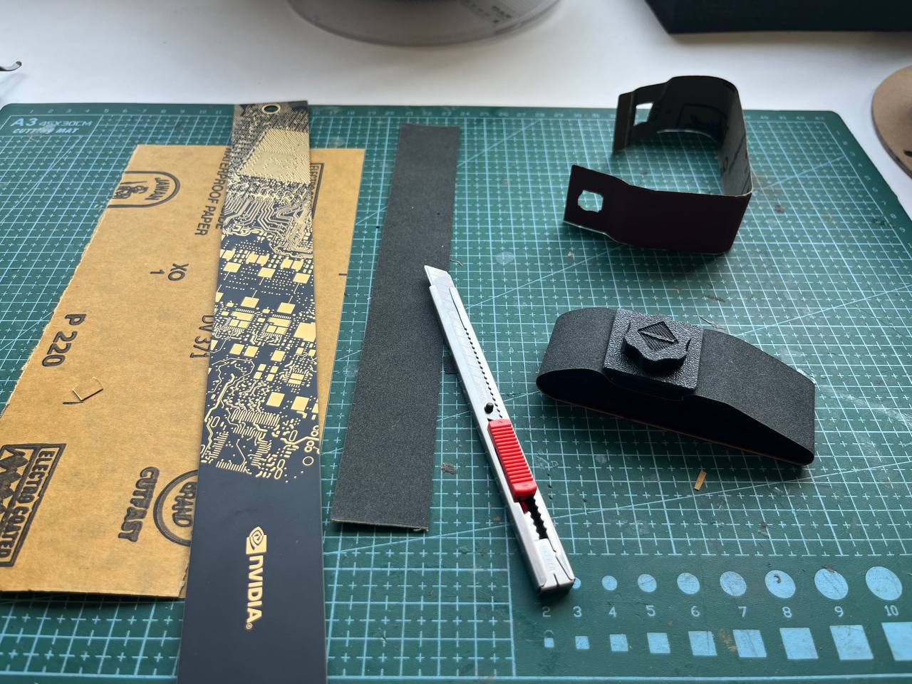
Sanding: We used a power sander, but for the small places that didn't work so we cut sandpaper to fit on a small handheld 3D-printed holder.
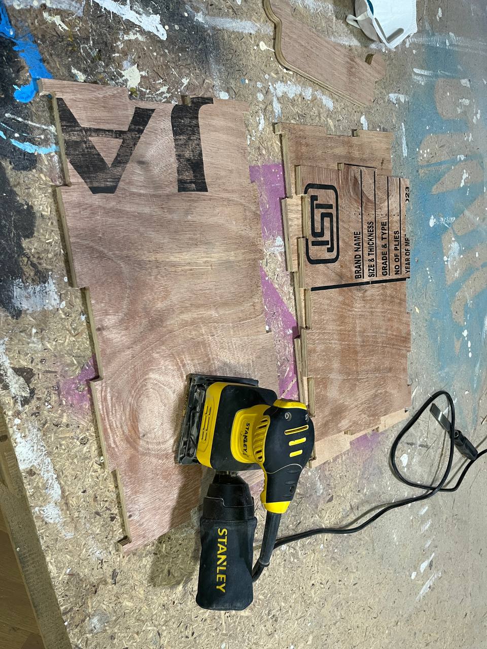
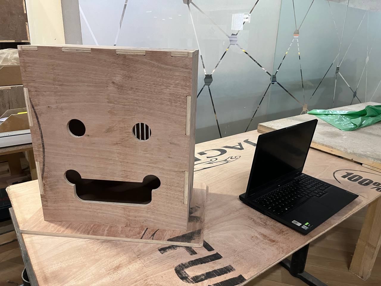
Fitting it together and final result: it fit perfectly, just a bit tight but with a hammer it forced in and cannot easily come out.
Hero Shots + Analysis
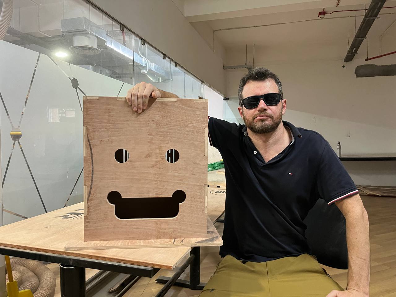
The CNC week gave the perfect opportunity to make a prototype of the structure for final project. This is the first photo with myself and my replacement. It's not completely bad.
Pros:
- Very strong.
- Mouth is sufficiently big to dispense candy.
Cons:
- Very blocky; better to have a rounded head.
- Eyes may be too big for the camera.
- Kerfed door is nice, but not secure.
- Rico thinks the mouth is creepy?
Design Files:
Parametric Head Design in Fusion (.f3d format)Parametric Head Design for production (.dxf)
Parametric Head Design CNC toolpath (.crv)
Parametric Head Design Toolpath for Shop Bot (.sbp)
All files (.zip)