
7.Computer controlled machining
Group Assignment
For the week, we had to create something using wood on a larger scale. I wanted to make something that was not only aesthetically pleasing, but also functional. When I was introduced to the concept of using wood flexures, I was immediately intrigued and wanted to explore the possibilities of incorporating them into my project. As a result, I decided to create a wooden bean bag and became fixated on adding 2D wood flexures to the design.
Fusion 360
For my design project, I selected Fusion as my preferred software for designing. I chose this software because I am familiar with its interface and because I wanted the design to be scalable, or parametric. Fusion was the obvious choice for this task. Additionally, thanks to the Doge Bone add-on, I was able to complete a significant amount of work within Fusion. This allowed me to create a more intricate and complex design with greater ease and efficiency

parametric design in Fusion 360 is a powerful tool that enables designers to create designs that are scalable and easily modifiable. By defining variables and parameters in the software, designers can make changes to the design quickly and efficiently without having to start from scratch. For instance, if I were designing a table, I could set variables for its height, width, and length, and if I later decided to make it shorter, I could easily adjust the height variable, and the software would automatically update the design. The ability to define complex relationships between variables also makes it possible to create intricate and complex designs. Overall, Fusion 360's parametric design capabilities make it an excellent choice for designers who want to create adaptable and scalable designs.

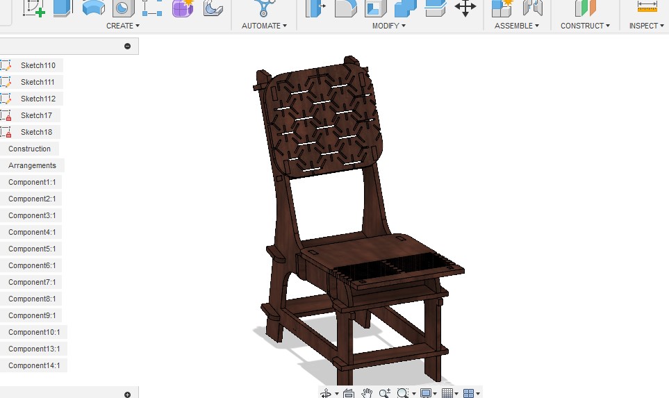
In Fusion, I began by creating the 2D structures for my wooden chair based on my calculations. Using a parametric design approach, I defined three basic lengths and the required seating position, then created 2D images in multiple planes. With two lofts and two cuts, I had the basic solid structure of the chair. From there, I smoothed out some details and the design was complete
Slicer for fusion 360
DownloadSlicer for Fusion 360 is a versatile tool that can be used for more than just 3D printing. In addition to creating instructions for 3D printing, it can also be used to prepare 3D models for laser cutting and 2D milling. The tool is able to slice 3D STL files into 2D images, which can be customized according to the user's preferred ply thickness and clearance. The software allows for editing of the number of slicer orientations, angles, and distance between slices, giving users a high level of control over the slicing process. To use the tool, all that is required is to export the file from Fusion 360 as an STL and import it into Slicer. With Slicer for Fusion 360, users have a powerful tool at their disposal for creating high-quality 2D images from 3D models, allowing them to create precise and accurate laser cut or 2D milled parts and products with ease.
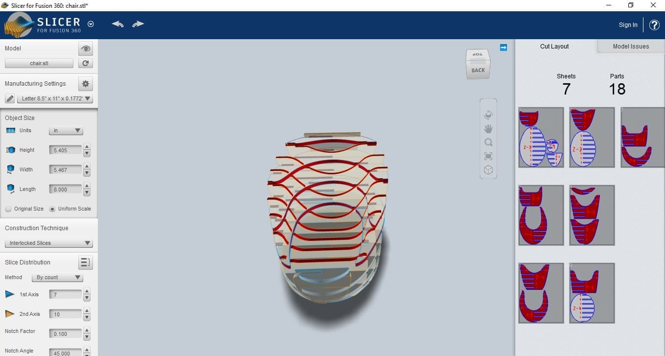
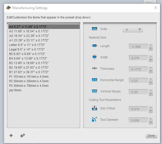
Slicer for Fusion 360 also includes a material editor menu that enables users to add and customize new materials to suit their specific requirements. The material editor allows users to specify the length, width, and thickness of the material, and to adjust other properties such as rigidity, flexibility, and color. By adding new materials and customizing their properties, users can achieve precise and consistent results in their laser cutting and 2D milling projects.

While the software is powerful and effective, it can be costly due to the excessive amount of plywood it consumes. As a result, I opted to utilize Fusion for designing instead, which allowed me to create a skeleton of the 3D structure. Although this approach was not without its challenges, I was able to break down the larger shapes into smaller pieces to reduce the amount of wood required.
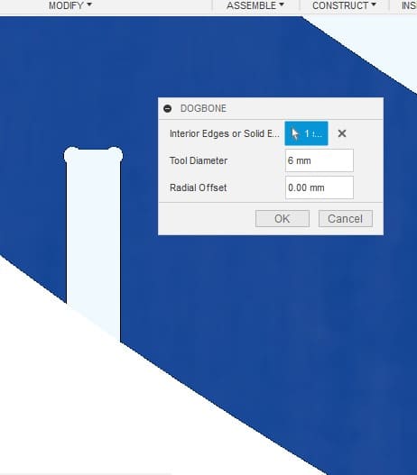
Dog boning
Dog boning is a technique used in wood cutting to create precise and snug-fitting joints between two pieces of wood. This technique involves cutting out a small notch or groove at the end of one piece of wood that perfectly fits the shape of the other piece of wood, resulting in a flush and stable joint.
In Fusion 360, dog boning can be achieved by adding a plugin to the software. This can be done by accessing a GitHub page containing Fusion 360 add-in scripts that aid in creating dog bones quickly and efficiently with just a few clicks. By utilizing this plugin, what could have been a long and arduous process is simplified, reducing the amount of time and effort required to create precise and snug-fitting joints in woodworking projects.
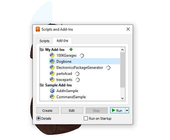
This feature is particularly useful for woodworkers who want to incorporate dog boning into their designs, but are not familiar with the process or lack the necessary skills to perform it manually. The Fusion 360 plugin makes it easy to add this technique to woodworking projects, resulting in strong and stable joints.
Arrange
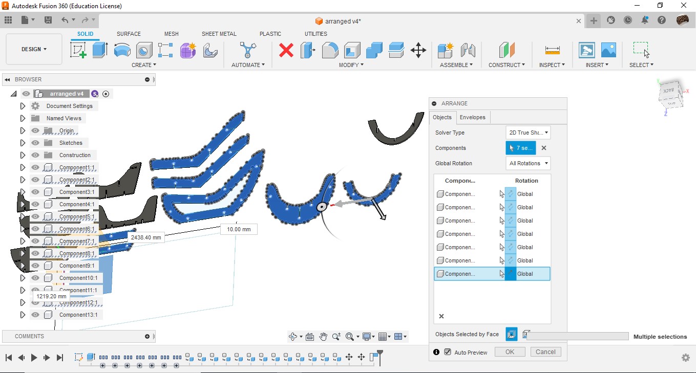
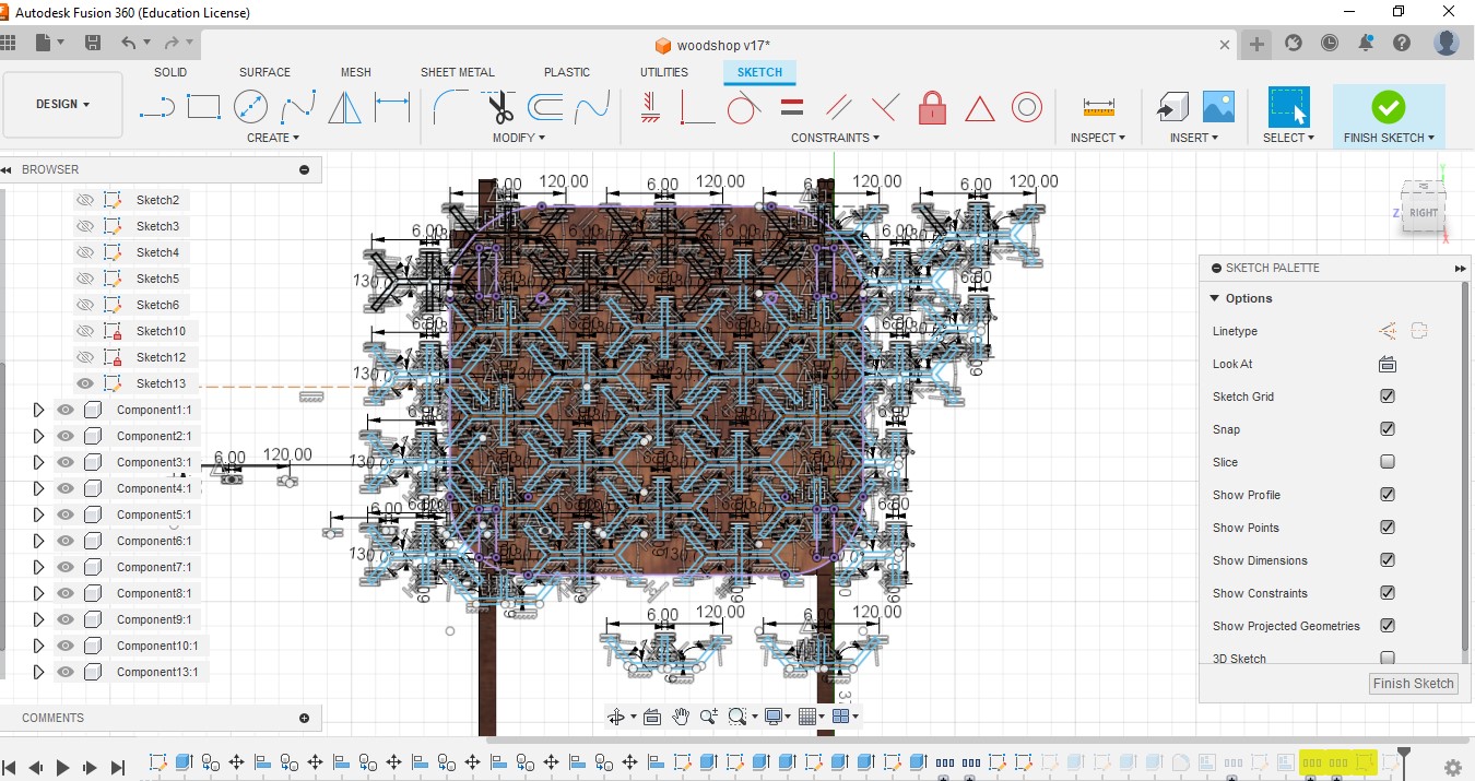
I used the Arrange tool in Fusion 360 for my 2D wood cutting project to arrange my design in the most efficient way possible. Since my material was an 8 foot by 4 foot plywood sheet, I wanted to minimize waste and maximize the number of parts I could cut from a single sheet. With the Arrange tool, I was able to easily position my design elements in a way that made the best use of the material available. For example, I could group parts that needed to be cut from the same piece of plywood together, or position parts in a way that reduced the amount of leftover material after cutting.
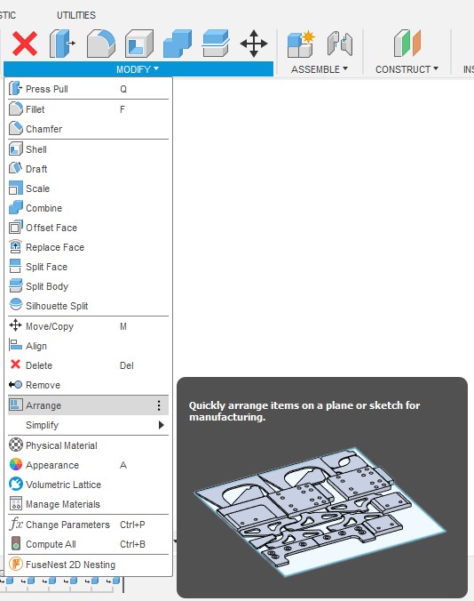
To activate the tool go to Modify << Arrange and add the constrains such as the ply width distance between designs.

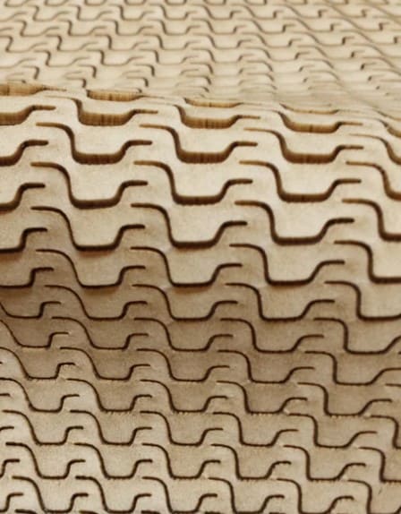
Kerf Bending
something I stumbled while surfing in the net.Another one
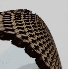
Kerf bending is a woodworking technique that involves making closely spaced cuts or grooves, also called kerfs, on one side of a wooden board or sheet in order to make it more flexible and easier to bend. Once the kerfs have been made, the wood can be bent along the grooves to create curves or other shapes. The closer the grooves are spaced, the tighter the curve that can be achieved.

Something I stumbled across while surfing the net
From the start of the week, I wanted to integrate kerf bending into my woodworking. According to my design specifications, I required a bending design that could bend not only in one direction but in two directions because of the balling curves present in the design. While browsing for that, I found a website with different designs for 2D cut flexures in plywood using laser cutting method. The designs were beautiful and functional. Even though it was laser cut, I was able to change the design so that it would work on plywood.
From an existing design from our lab which was done by a previous alumnus, I was able to determine that 12mm plywood combined with a 6mm drill bit can be effectively bent with a 10mm flexure thickness. So, from that information, I wanted to create a design to cover my chair.
The Other Design
To carry out this assignment, I wanted to have something simple. I left it because it was too big and consumed too much wood. It was impractical due to its complex design, even if I had designed it, I needed to calculate the coordinates to convert it into a working design. So, I need to do my experiments and do my worth. The assignment clearly stated that it should be something big, so I decided to go with a chair. Also, I wanted to do some experiments with this chair. The chair should be able to handle the weight of a person; if it does not, it will break. Primarily, a chair is something that is used to sit on. It should be comfortable and able to handle the weight, with beauty being a secondary consideration."
So, with that in mind, I decided to design a chair. In order to do that, I needed to imagine the forces traveling within the wood. The bottom position is more likely to have to diverge from its position, so I added a piece to keep it in place. If the bottom legs diverge, it may break the chair. However, for the assignment, I am only able to create wooden joints, and I have to use plywood. Therefore, I gave no importance to the looks initially, and it may resemble a coffin.
But I am certain that it can handle weight, so it is enough for me. For the place to sit and for the place where the back rests on, I needed to create something else. The base is the area that experiences more weight, and it should be sturdy. There is a bend at the seat as per design, so I intend to incorporate a curved bending at that place.
I have been trying to bend wood with certain patterns from the internet. Although it has been used for laser-cut kerf bending, I think I can replicate it in wood by introducing patterns into the wood itself. Deepu K is the only person who has experimented with it, and his perception and experience were unique in that matter. So, I asked him for advice after I conducted the test cutting for kerf bending. During the experimentation, I found that the linear pattern was very hard because it had too much material in between, and the complex kerf bending with the pattern had some design issues. Deepu mentioned that it had too much material in one place, and if it is removed, it will work. Therefore, I redesigned the work with a different pattern.

As our instructor suggested, I decided to create a small laser-cut replica of the design using cardboard. I used the arrange function in Fusion 360 to position all the wooden parts accordingly. After that, I scaled the design using a ratio calculator and Inkscape. I successfully created a small replica using the laser cutter and cardboard, and everything was working fine. This gave me the confidence to proceed with manufacturing.

Manufacturing
The ShopBot PRSalpha 96-48-8 is a computer numerical control (CNC) router designed for use in woodworking, plastics, and other manufacturing industries. It has a cutting area of 2438mm by 1219mm by 203mm, allowing it to handle large sheets of material and thicker stock. Equipped with a powerful spindle motor and precision cutting system, it can achieve a cutting speed of up to 4572mm/min. The machine features a digital indexer for precision alignment, a tool length sensor for automatic tool calibration, and a dust collection system for a cleaner work environment. It is controlled by a user-friendly interface and software package, allowing users to create complex designs and program the machine to execute precise cuts with minimal error.

Setting up Shopboat
The setup of the shopbot is an easy task. First, we need to set the machining parameters for the machine, tools, and the material to be milled. Then, we can add CAM (Computer-Aided Manufacturing) to the machining operation. The machining is done in loops, and it is defined whether the machining is done inside or outside the desired shape. The machining process needs to be performed carefully to achieve the desired shape.

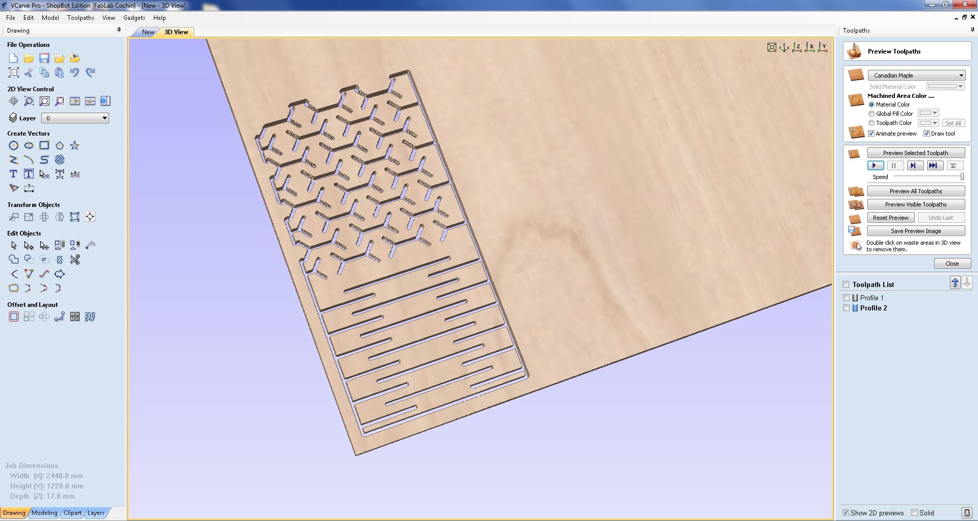
In V Carve software, the term 'Job Setup' is used to describe the configuration process for a particular project or job. In our project's context, the Job Setup in V Carve involves specifying the dimensions of the plywood material. More specifically, we set the width and length to 2440 mm and 1220 mm, respectively. To ensure accuracy, we conducted a manual measurement of the plywood's thickness and determined it to be 17.8 mm. V Carve offers various Tool paths, but for our purposes, we primarily utilize the Pocket and Profile Tool paths.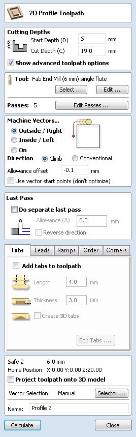
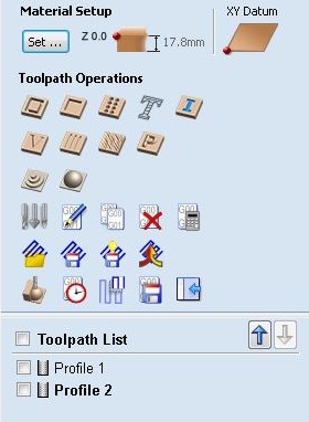
Additionally, I added tabs in place to keep the material attached to the wood during machining. This prevents excessive strain on the plywood and ensures it does not separate from the ply. For the machining process, I used a 6 mm bit as instructed by the instructors. The machine parameters, such as spindle speed, were also provided by the instructors. We added these tool and material parameters to the machine without any issues. The machining itself was fairly simple and easy. After completing the setup, I saved the machining profiles so that I could load them into the machine.
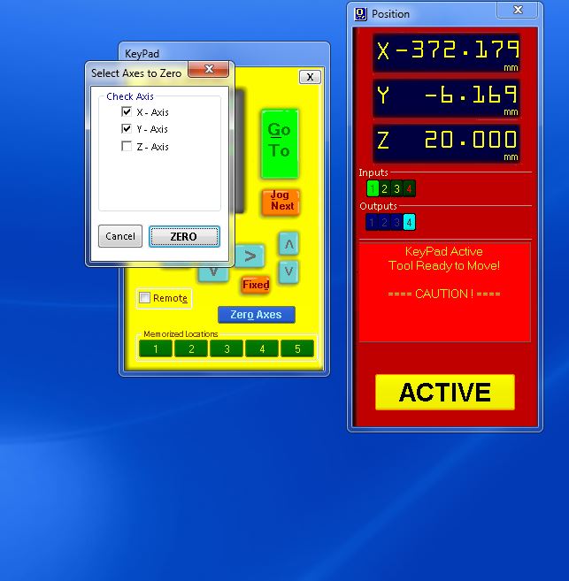
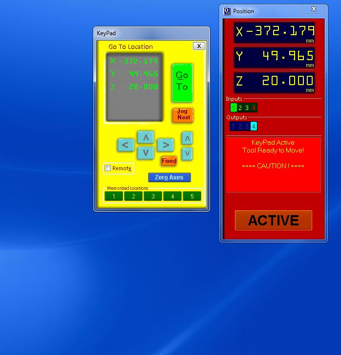
To set up the machine, we need to open the software for the Shopbot and jog the X and Y axes using the GUI (Graphical User Interface). Once we get the machine to the desired position, we need to fix the X and Y axes. The Z axis can also be calibrated in this way, but I decided to use the calibration method provided by the machine. To calibrate the Z axis, I selected 'Calibrate Z Axis' and used an alligator clip and a plate for calibration. I ensured that the alligator clip is conducting by touching it to the plate. After that, I connected the alligator clip to the tool and touched it once again. Then, I clicked 'Start'. The tool will come in contact with the plate, completing the circuit and setting the Z axis as zero. Finally, I just need to select 'Cut Part' and choose the program saved from the V-carve. I can then start my milling process.
Before starting the milling process, I need to turn on the spingle and the vacuum. When the window appears, I simply need to rotate the spindle and start the machine for milling.

The milling process itself was easy, although some tabs failed during machining, resulting in two parts of my milling being ruined. Unfortunately, I had no other option but to discard those pieces and create new ones. Fortunately, the lost pieces were expendable and required less material to replicate, so I decided to proceed with that.
Regarding the kerf bending, the design turned out to be more flexible than I intended. I wanted some flexibility, but not to this extent. Nevertheless, I decided to proceed with it. After that, I was ready for assembly. Surprisingly, I didn't need to add any clearance since from previous experiments it was clear that no clearances were required. I could easily slide the pieces into the notches without needing to file anything. Additionally, I aimed for a tight fit after machining.
After the machining, I was ready to assemble the chair. I took the hammer, and since the pieces were a tight fit, it was challenging to fix them together. However, with some effort and the trusty hammer, I managed to hammer all the pieces together, and the assembly was complete. The chair turned out to be heavier than intended, but it was sturdy as it should be. We tested it by allowing others to sit on it, and it looked good.
Once the assembly was complete, it was time for testing. I asked everyone in the lab to test the chair, and everyone was happy to oblige. Overall, the chair looks good and has received positive feedback.
