Week 12: Mechanical Design, Machine Design
Objectives
These are the tasks for this week:
- Group Assignment:
- design a machine that includes mechanism+actuation+automation+application
- build the mechanical parts and operate it manually
- document the group project and your individual contribution
Group Assignment
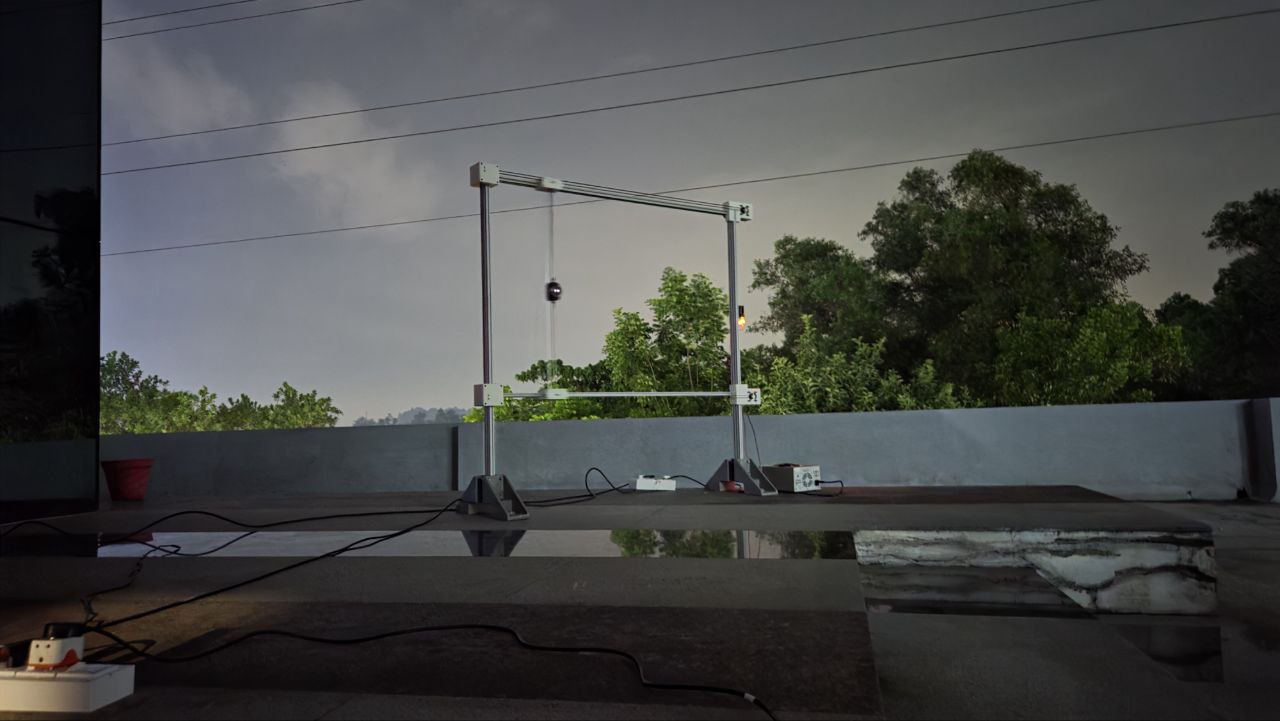
For machine week, we built Velichapaad; a machine that automates a photographic technique called light painting.
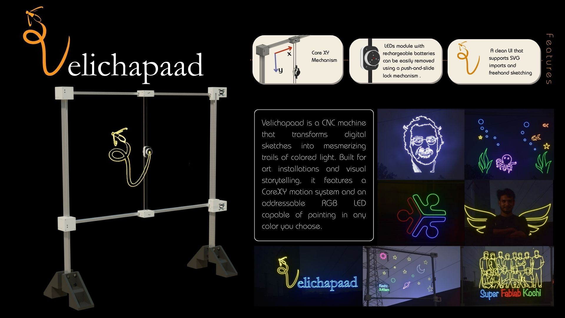
These are some of the images/videos were able to make using our machine.
To know more, check out our group assignment.
Individual Assignment
Brainstorming
Many ideas were discussd over the course of two days. First we had finalised on making arcade games, but due to time and skill-related constraints, we decided to do something smaller. Some of the ideas I pitched include:
- Omelette maker
- Automatic clothes folder
- A physical pin-pong game machine
We finalised on making an automatic light painting machine due to
- Only a very small modification to existing CNC machine was required
- The results are visually very pleasing to look at, which would make it a very good idea to present to audiences without going deep into the technicalities.
Testing Threaded Inserts
I used Fusion 360 for CAD designing all the parts listed here, including threaded inserts
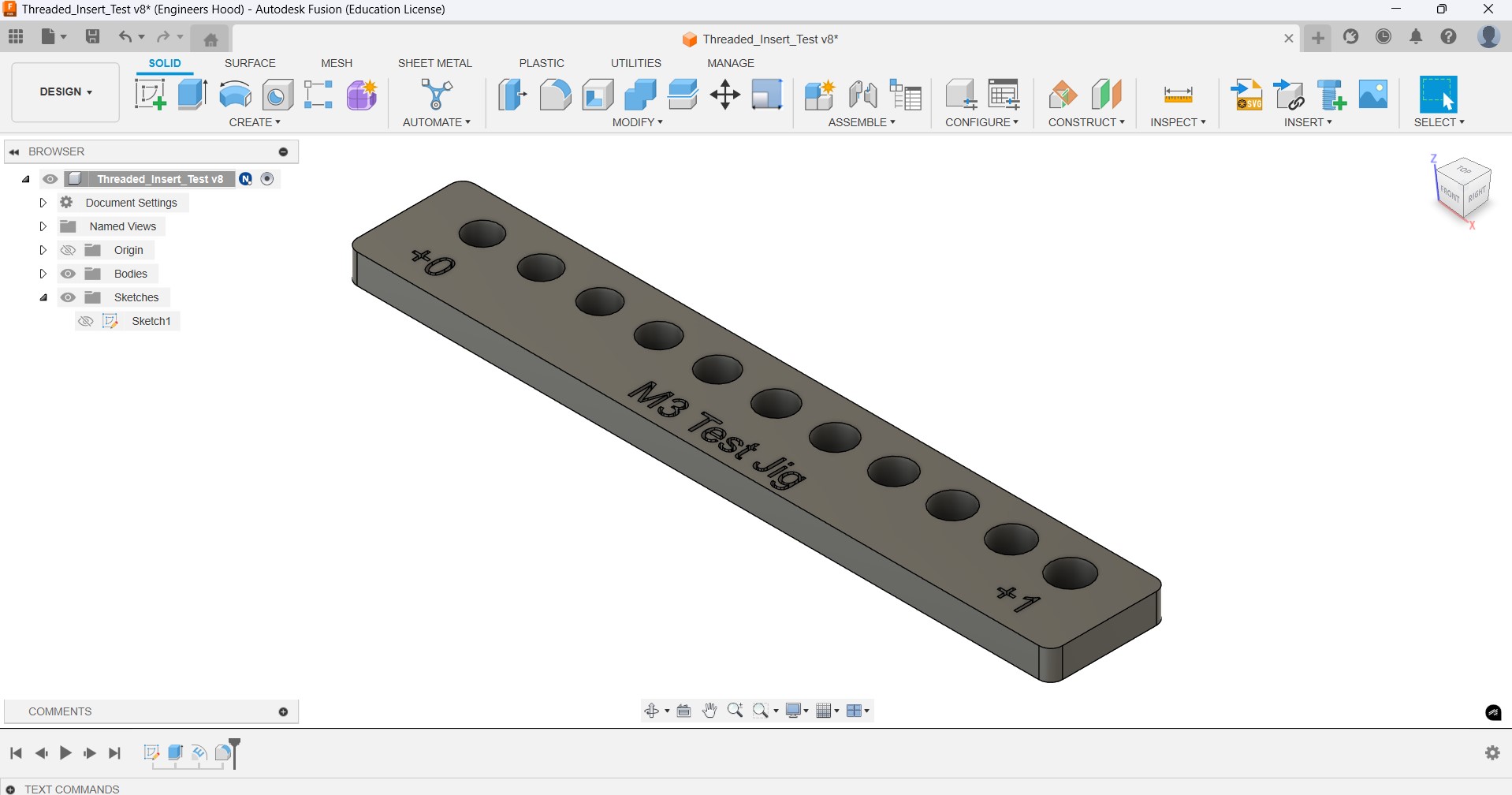
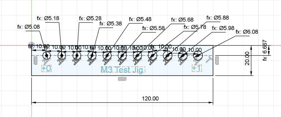
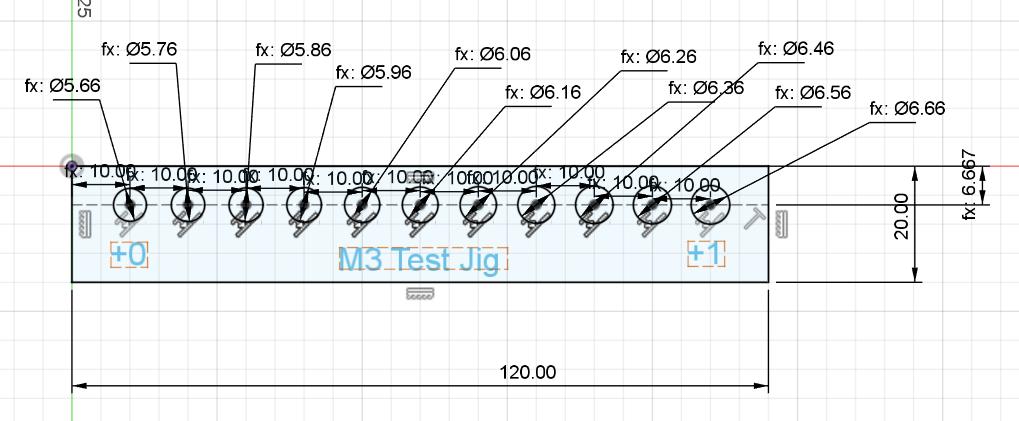
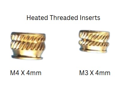
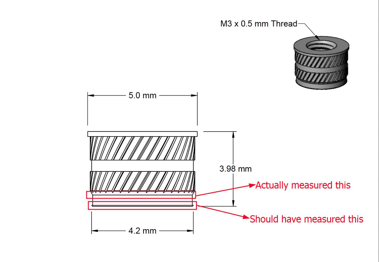
I tested M3 and M4 threaded heat inserts. Due to a mistake I made while taking measurements of the
outer diameter, I can only take absolute diameter measurements for reference and not in increments
of D+1,+2 etc., where D is the outer
diameter of the bearing. Click here to see what mistake I made and
how to measure the outer diameter of the outer bearing
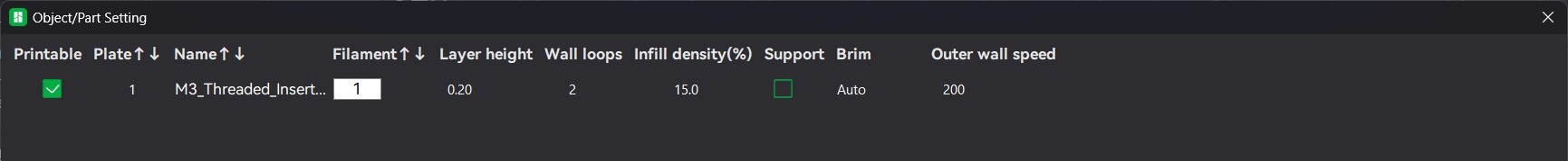
I followed the following slicing settings for both M3 and M4 threaded inserts
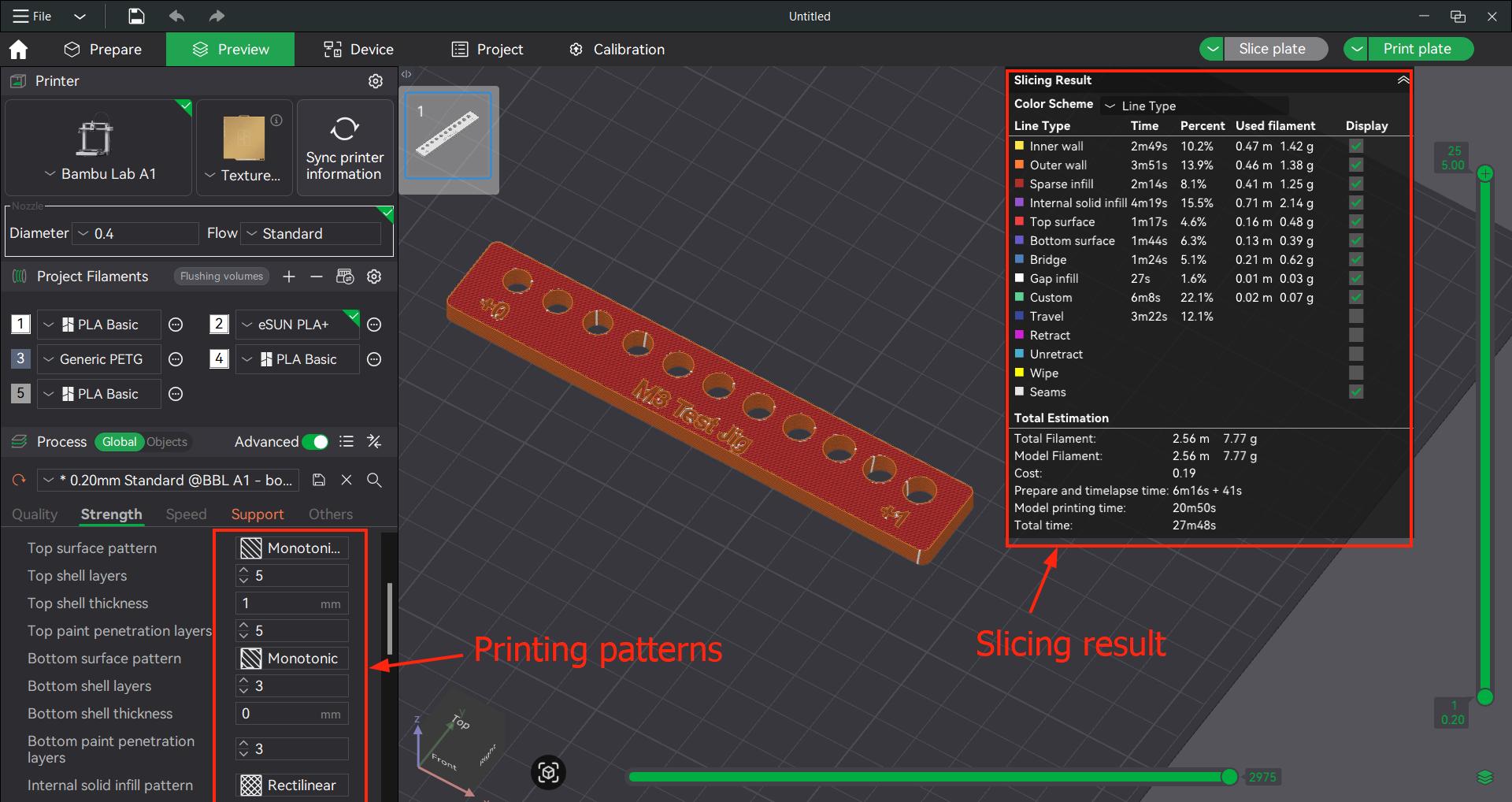
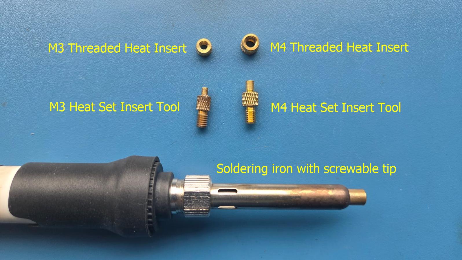
We have to heat the soldering iron to 220 degree C. Additionally it is good practice to use dedicated tips for heating the inserts like we have done.
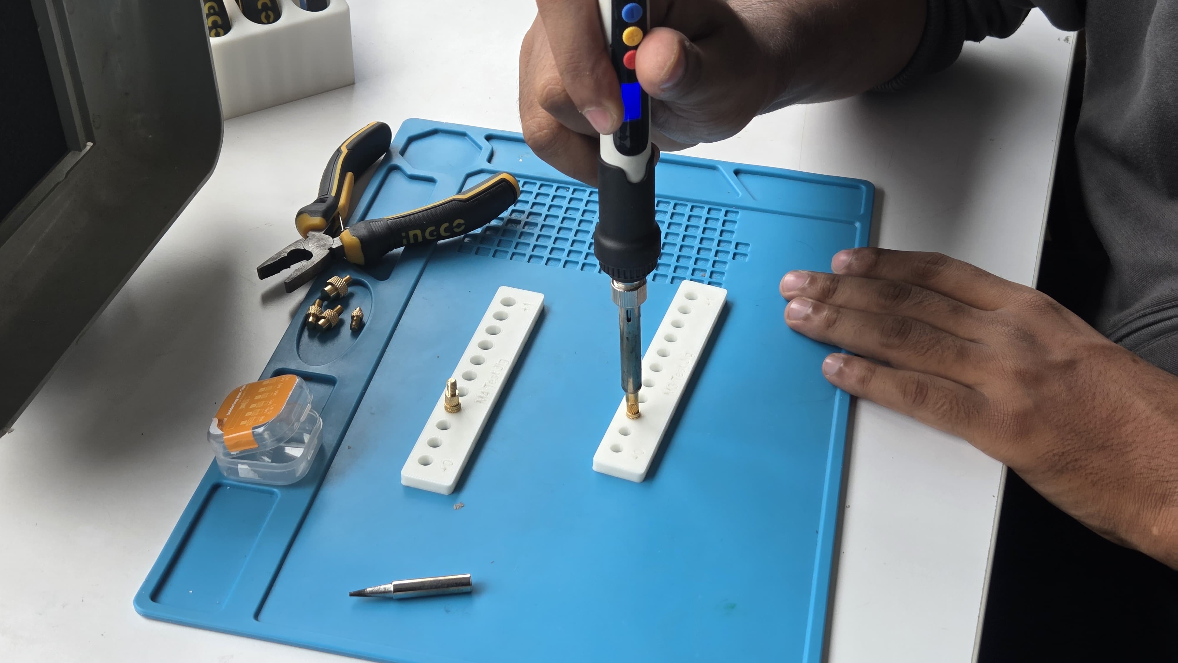
This is the final output of the test.
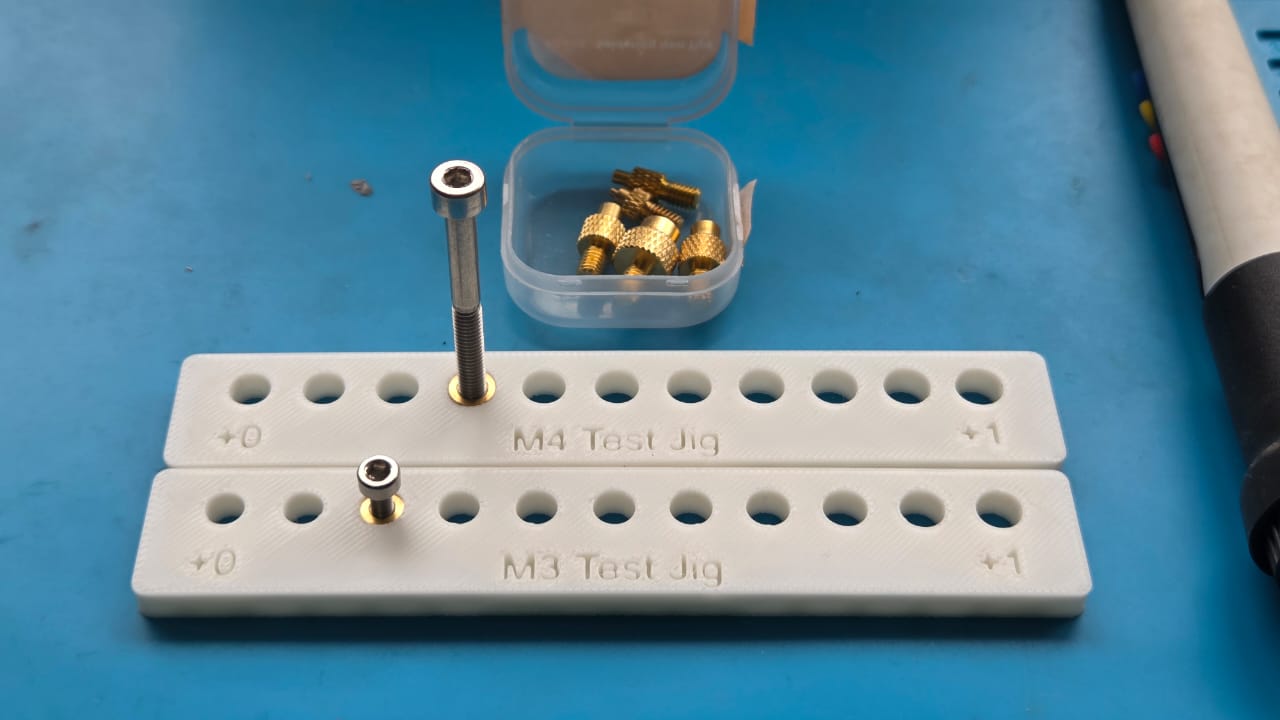
Based on the observations, we require hole diameter of 5.28 mm and 5.96 mm for M3 and M4 heat inserts respectively.
Testing Belt Locking Mechanisms
I continued the work that Akash's had initially started of trying to create a way to easily attach and lock the belts at the LED mount in such a way that it can be easily assembled and dissassembled. I tried different iterations of thhe dovetail joint that tightens as the belt is pulled under tension. My final design had a way to loop the belt and attach it inside of the joint mechanism.
| Feature | Description | Result |
|---|---|---|
Belt Test 1 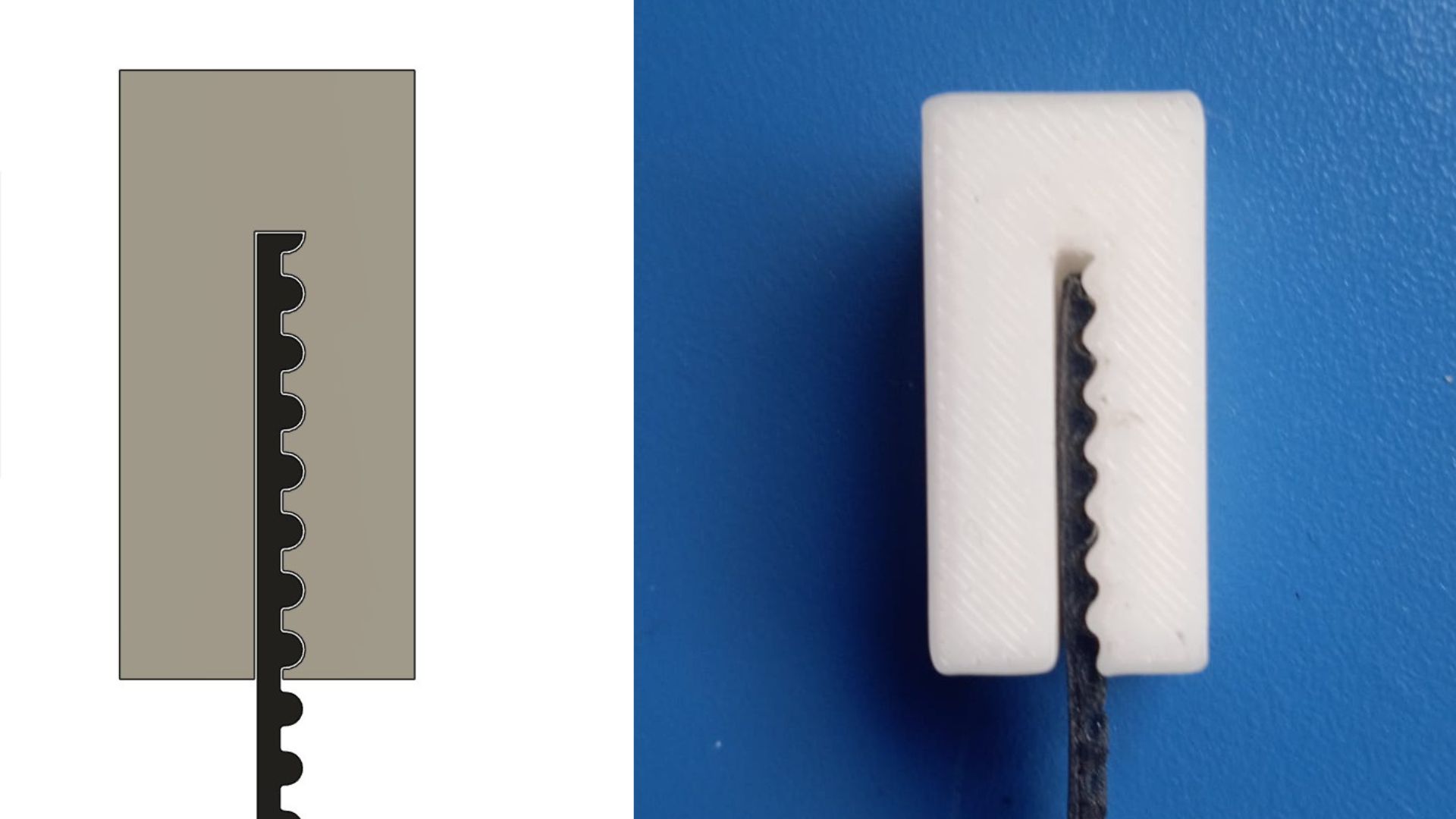 |
Enclosure to hold the belt at the light mount | No resistive force to hold the belt in place. |
Belt Test 2 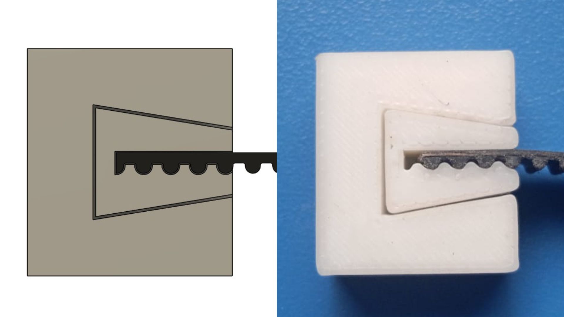 |
Added a dovetail joint to improve the resistive force keeping the belt in place. | Now it works much better, but the clearance between the two parts is too much. |
Belt Test 3 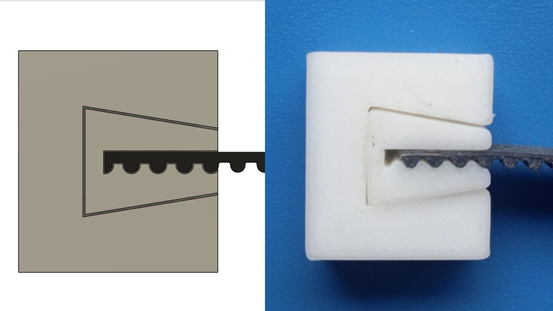 |
Reducing the clearance between the two parts by 0.5 and 1 mm offset | Not working as expected, the belt comes off much looser this time, redesigning it so that the belt makes a loop. |
Belt Test 4 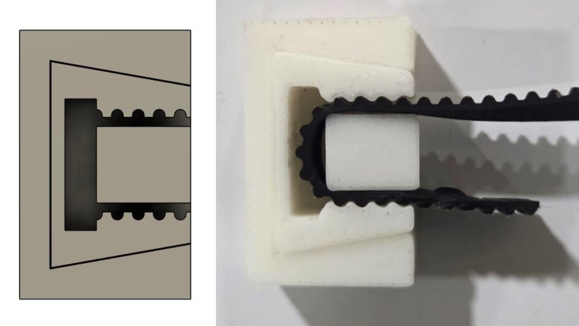 |
Modified the design to form a loop | Works much better once I reduced spacing for belt by 0.1 mm, but now the belt is not centered, will have to center it. |
Belt Test 5 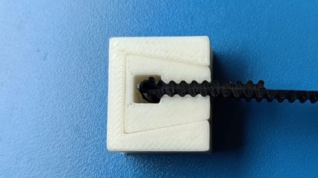 |
Modified the design so that belt forms a loop over itself | The belts slip against each other and come free. Will have to go back to previous design and modify it. |
Belt Test 6 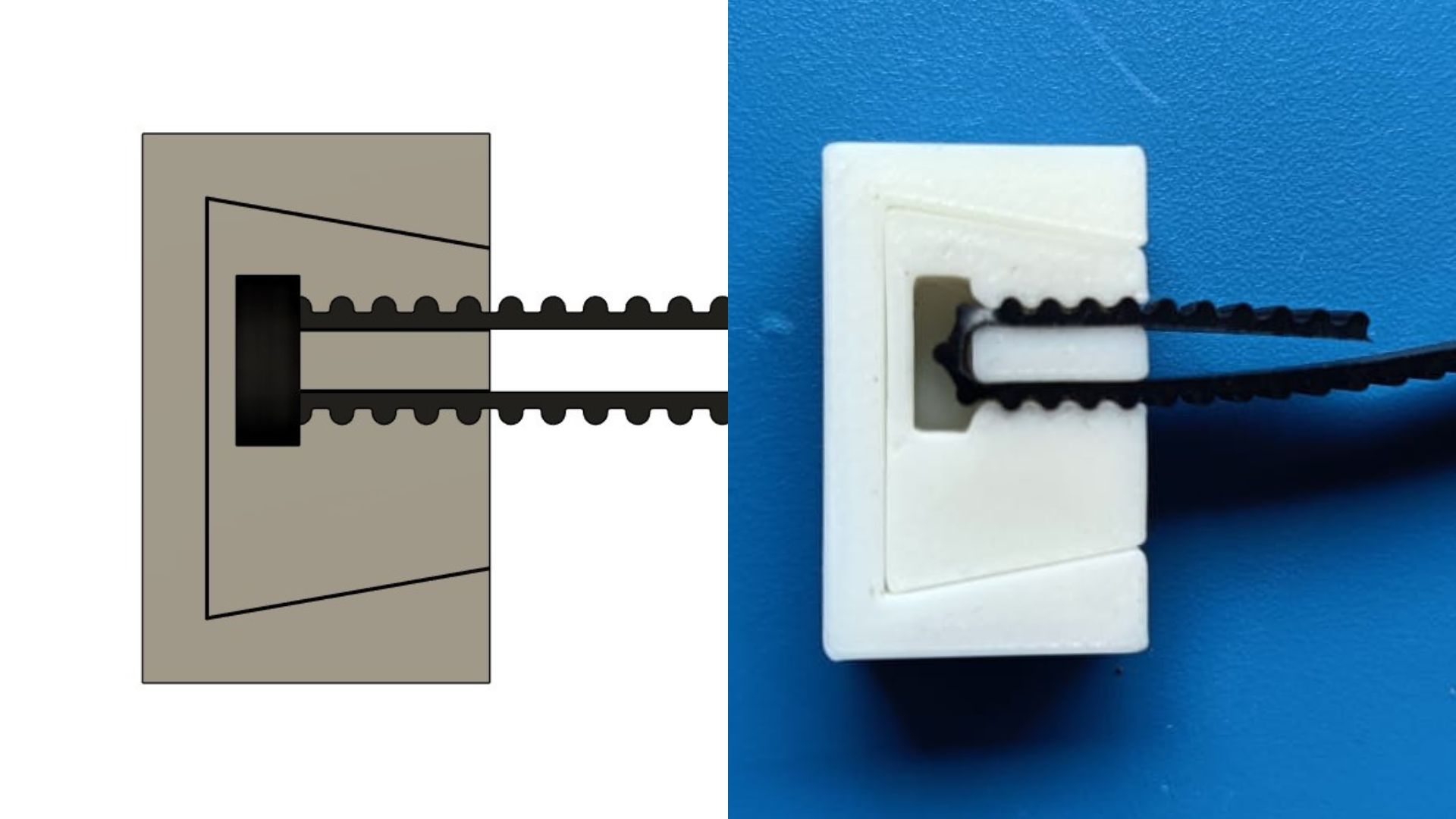 |
Modified design so that that the belt comes in the center and the whole joint takes up minimum horizontal space | This version works very well, will proceed with this version. |
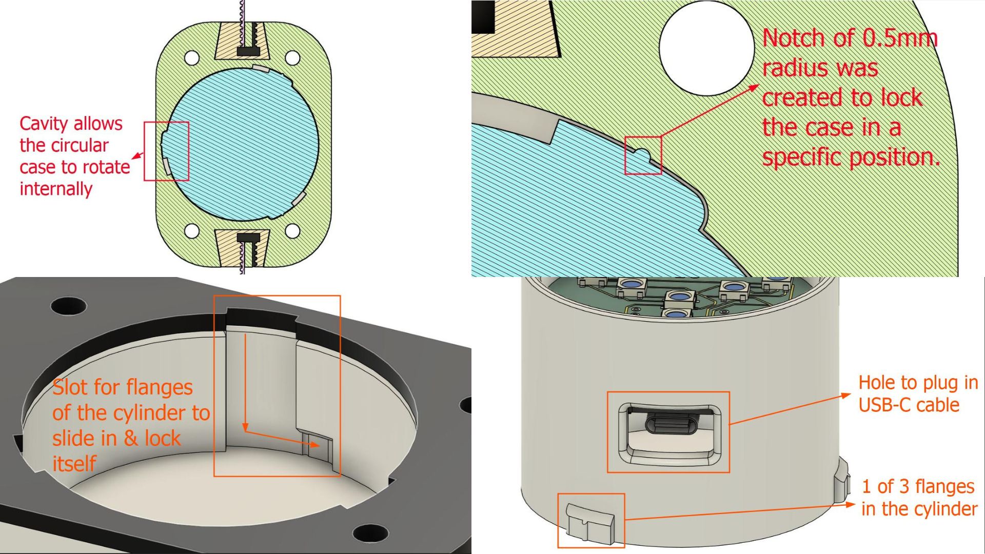
Integrating the Push-Slide-Lock
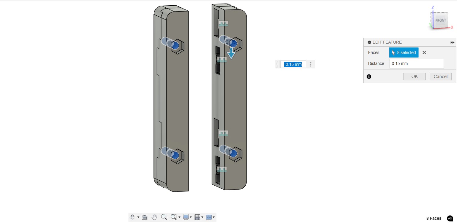
I modified Tom's original idea of the push-slide-lock mechanism into the LED mount design in a manner that is easily 3d printed with minimum supports
Here is a video walkthrough of the CAD design of the mount before testing and modification made by Akash. See 'Updates' section in Akash's documentation
This is a video showing the locking mechanism working
Designing the Housing for the CNC Programmer
We used a 3 Axis wireless CNC programmer called NeoPi, made by Saheen Palayi. I was tasked to make a simple housing to attach it to the frame of our machine Since laser cutting is faster than 3D printing, we decided to make the CNC hosuing from black acrylic. I designed something very simple; two acrylic plates that house the CNC programmer, held together M3 standoffs. Holes for attaching the barrel jack for power using zipties were also added.
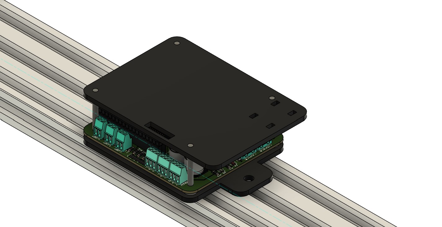
We used X tools laser cutting machine to cut 3mm acrylic sheets. We made a bottom and top plate and some small spacers to add height between the bottom base and the PCB.
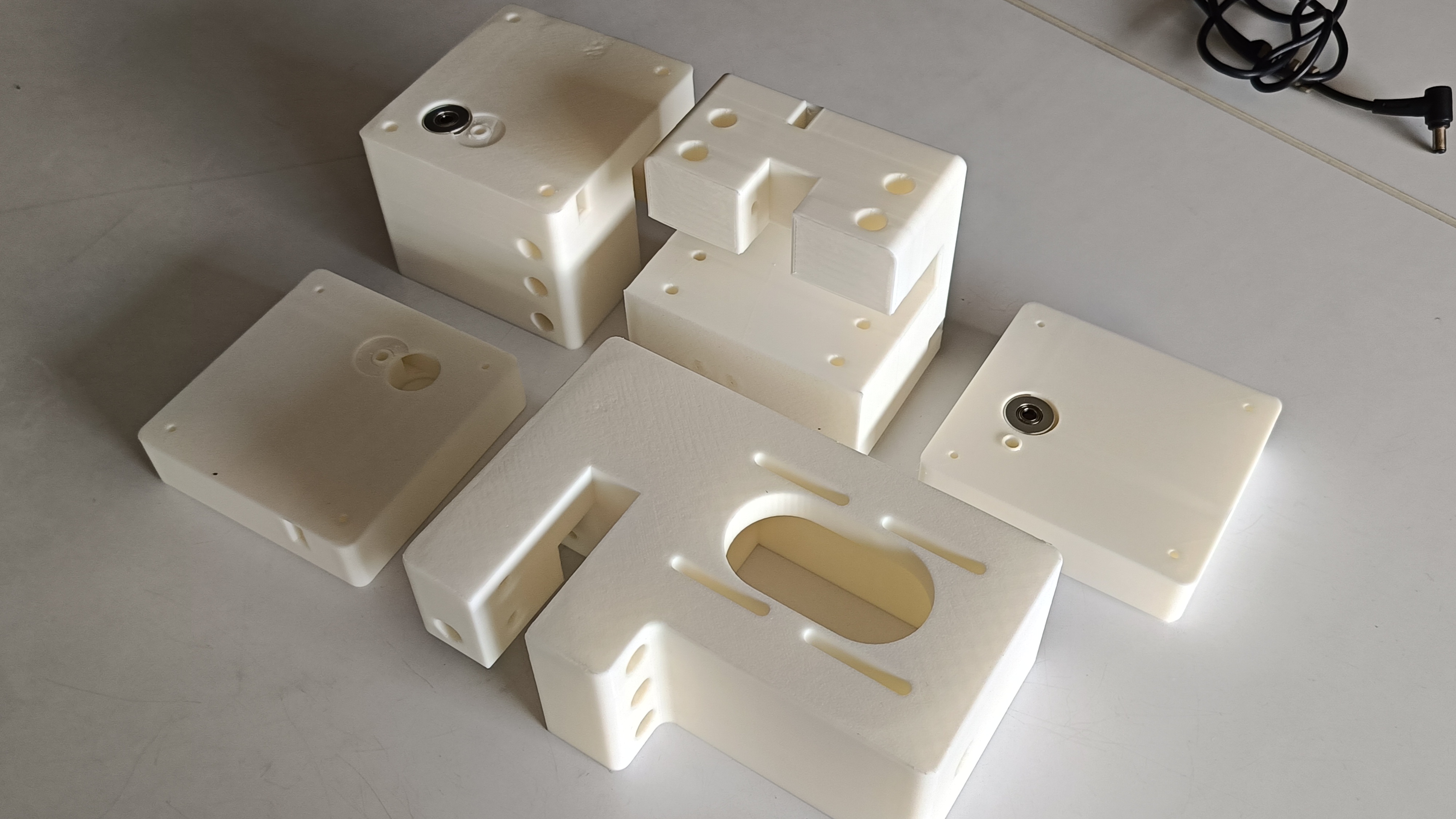
3D Printing
I was involved in 3D printing the parts. Taking the constraints of 3D printing into consideration, I added a 0.3 mm clearance to screw holes based on the screw hole test we conducted previously to allow the screws to fall in smoothly through the hole. It would be tightened in place using nuts at the other end.
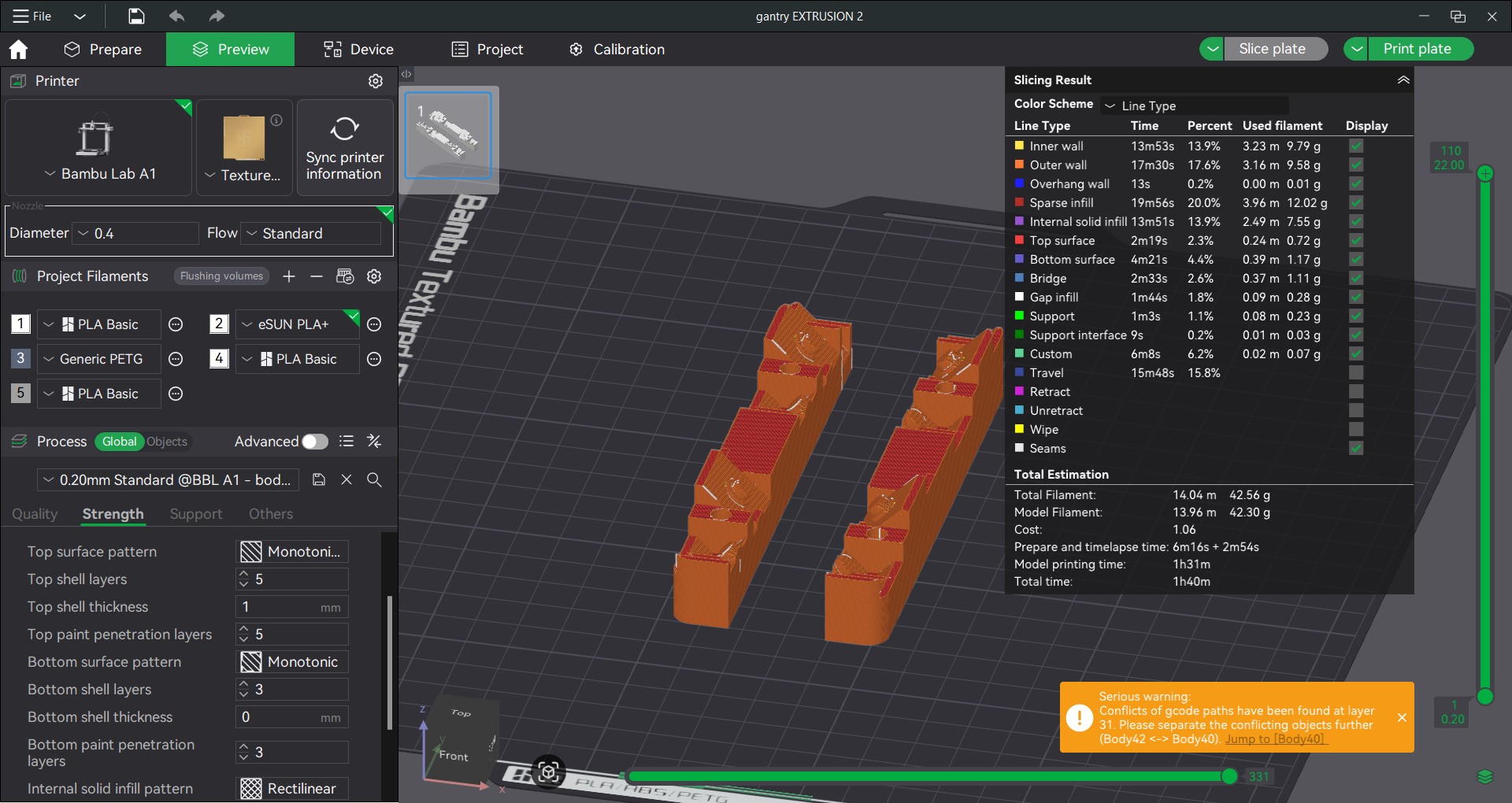

I followed the same slicing setting with all our prints as shown above
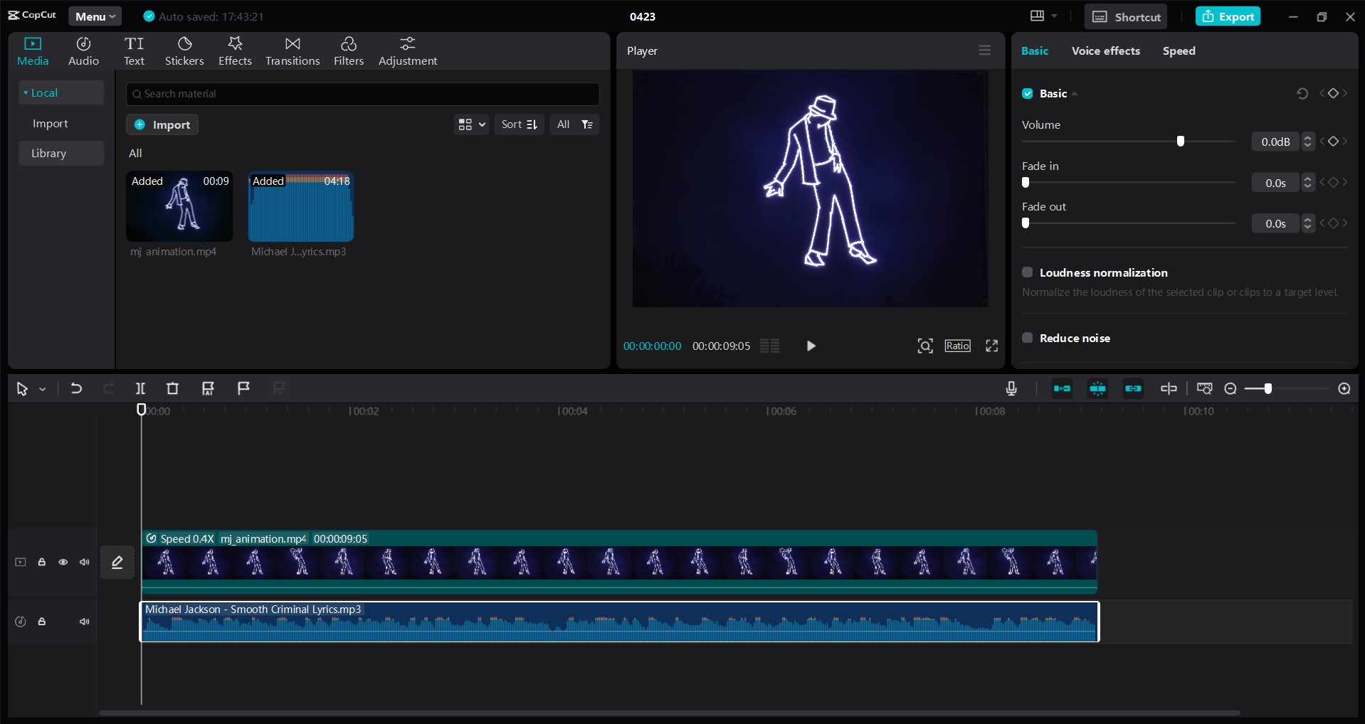
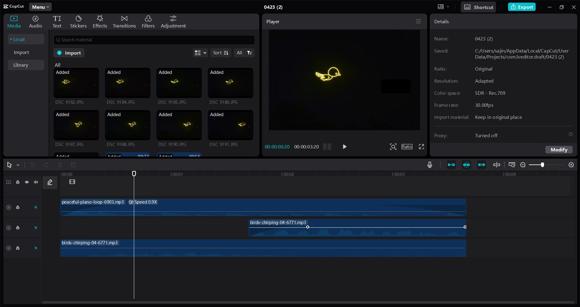
Animation & Sound
I also added sound for all of the stop-motion animation videos we made using our machine. Additionally, I made the stop-motion animation for 'Kili'. I used Capcut for this purpose
Documentation
I was also in charge of managing the group documentation. The strategy I followed was the following:
- Once brainstorming is done and each person has been assigned their tasks, update the group documentation with individual sections for each person to showcase their work.
- They then share their documentation in Notion. The reason we chose to do this instead of letting everyone git pull and push their updates was to avoid merge conflicts when multiple people are involved. Instead, only I would git pull and push the updates
- If any documentation was missing, I updated the responsible team member and they provided me with the missing content, which I would then update in the website.
Conclusion
These 2 weeks I was mostly involved in CAD designing, 3D printing, stop motion animating, and documentation, and assembly of the machine
Mistakes & Solutions
- Measuring Heat Inserts: I used the wrog dimension for measurement, so I used the absolute diameters for the design instead of increments.
Design Files
Click here to access the design files