Week 12
Machine Building
This week’s assignments involve designing a machine that integrates a mechanism, actuation, automation, and a specific application. You are required to build the mechanical components and operate the machine manually. Additionally, you must document both the group project and your individual contributions. Once the machine is built, you will move on to actuating and automating it, followed by thorough documentation of the entire process, highlighting both the team effort and your personal involvement.
Project Planning
This was one of the most important and time-consuming parts of our machine-building week. Initially, our team had not yet decided on what kind of machine to build, which led to a lot of discussions and brainstorming sessions. We spent considerable time throwing around various ideas, trying to find something innovative yet feasible within our time and resource constraints. During one of our sessions, we were watching videos for inspiration and came across a project where someone had built a ping pong game using a CNC machine. That’s when inspiration struck—we thought, why not build a light painting machine?
The concept involved attaching a NeoPixel LED strip to the end effector of a CNC-like setup. The machine would be capable of moving the light source in the X and Z directions, allowing it to “draw” patterns or images in mid-air. By taking a long exposure photograph while the LED moves, we could capture beautiful light trails forming complete images or text—essentially painting with light in a 3D space.
I was the one who initially suggested the idea of creating a light painting machine. Everyone in the group contributed actively with their own suggestions. While some ideas were creative, they turned out to be too complex or unrealistic to complete within the available time. However, through collaborative discussions and refinement, we all agreed that the light painting machine struck the right balance between creativity, technical challenge, and feasibility. This final idea brought the whole team together and got everyone excited to start building.
Design
The task that was assigned to me was to design the machine.The first step was to design the features needed for the machine and depending upon the at the machine had to be designed. Our idea was to design a machine that can paint with light so we wanted the light on the machine to move in x and z direction so that the machine will be able to draw a picture or a pattern in air and the path of the light can be captured by a camera and and by taking a long exposure shot the pattern can be seen clearly.
The second step was to design the mechanism of the machine,since we needed a mechanism with minimal components andit should be fast and very less weight have to be carried we selected the core XY
CoreXY:" A Brief Overview
AI Prompt : Give a brief about core XY
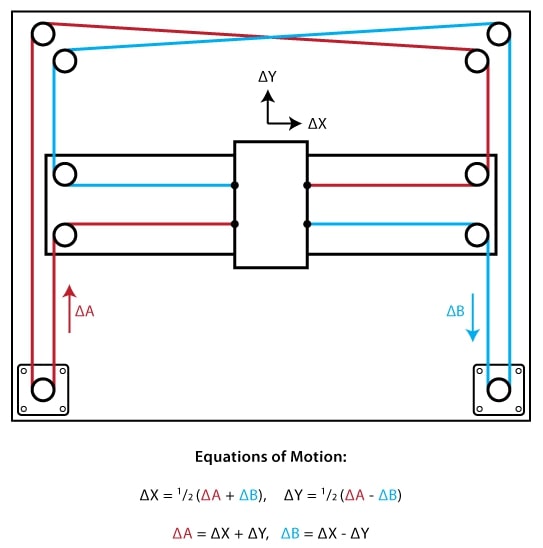
"CoreXY" is a motion system commonly used in 3D printers and CNC machines, designed to enhance speed, precision, and mechanical stability. Unlike traditional Cartesian systems where each axis is driven by a separate motor, CoreXY uses a coordinated dual-motor system to control both the X and Y axes. The motors remain stationary on the frame, reducing the moving mass and allowing for faster, more precise movements. This design is particularly beneficial for high-speed printing and applications requiring fine detail.
One of the defining features of CoreXY is its unique belt routing mechanism. The system employs a series of crossed belts that translate the combined motion of two motors into precise X and Y movements. This arrangement allows the print head to move smoothly while keeping the motors fixed, minimizing vibrations and improving overall print quality. Additionally, because the motors are mounted on the frame rather than the moving gantry, CoreXY printers can achieve larger build volumes without significantly increasing the machine’s footprint.
CoreXY" offers several advantages, including faster print speeds, better accuracy, and reduced mechanical wear due to lower inertia. However, it also comes with challenges, such as the need for precise belt tensioning and synchronization between the two motors. Despite these complexities, CoreXY remains a popular choice among advanced users and is commonly found in high-performance 3D printers like the Voron, Ratrig, and Hypercube. Its balance of speed, precision, and scalability makes it ideal for both hobbyists and professionals seeking reliable and efficient motion systems.
The next step was to select the components for the machine like pulley,motors belts etc..,then all the measurement we made and the cad models of these components were downloaded for this i used McMaster Carr extension in fusion and also downloaded some files from grab cad and some were taken from existing designs.
Design
First i started by drawing the path of the belt, Pulley and the motors in the a sketch which is used as reference for designing the rest of the components in the design.
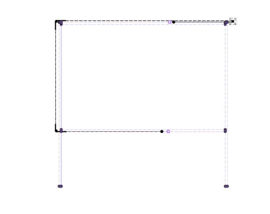
and then depending on the second belts position made a plain at an offset and and followed the same step and made the sketch for the second set of pulley and belt
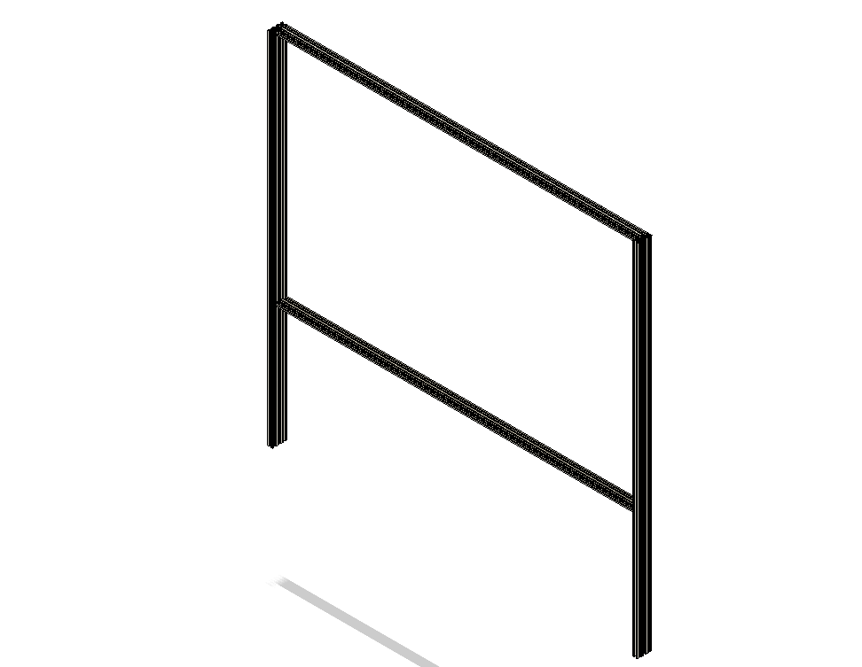
Then i imported the extrusions and arranged it in the correct way.
Then i started with the motors mounts, for this i imported the the nema 23 motors design and depending on that designed the made a mount to properly hold the position of the motor in place and a simple slots on that the bets can be properly tightened.While designing i made sure to add proper screw holes so that the extrusion can be properly fixed, And i had given som e space so that L clamps can be used for more strength.
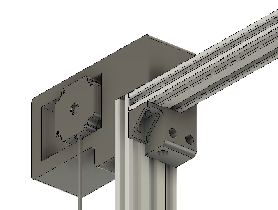
Then i designed the second motor mount which had to be mounted on the bottom section of the frame.Here i hade to make two slots for the belts to properly since the two sets of belts were in an offset.
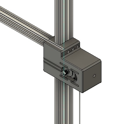
Next step involved designing the corner mounts here two teethed pulley had to me mounted in an off set and the corner mots have to to fixed to the extrusion, The corner was designed in two separates pieces so that the pulley can be easily mounted.
The corner mount have to be mounted to the extrusion for this i had provided proper screw holes and then i had provided space so that the L clams can also be mounted.
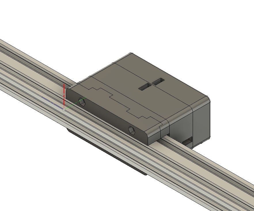
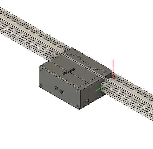
The next step was to design the fo this we got an already existing design of gantry that was used in other projects and modified it to our needs,here the gantry is divided into multiple pieces so that the pulleys can be easily assembled and the whole gantry can be easily assembled to the extrusions, each gantry contains one teethed and a teeth less pulley
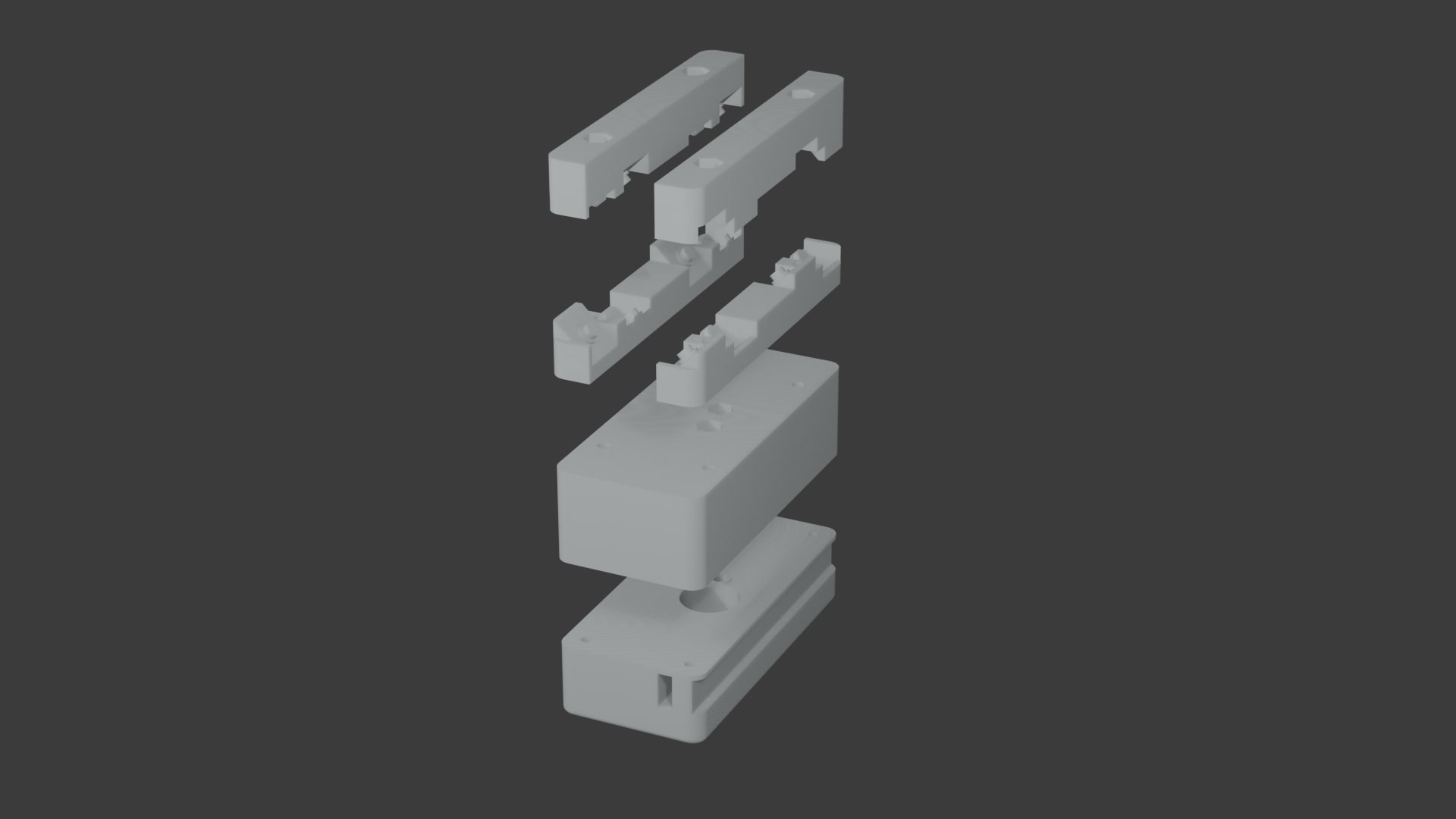
these are the views from both sides of the gantry.
During the design phase of the machine, I received valuable support and contributions from my teammates. The end effector, which plays a crucial role in the functionality of our light painting machine, was collaboratively designed by Noel and Tom. Additionally, Namitha contributed to the design of specific parts of the end effector, especially the enclosure for the NeoPixel LED. Since she was also responsible for designing the NeoPixel control board, it made sense for her to handle the casing as well to ensure proper fitting and integration.
Before moving on to manufacturing, we conducted several rounds of testing to validate our design and motion strategy. Most of the initial testing work was done by Ancy, who played a key role in troubleshooting and ensuring the reliability of the system. Noel also participated in the testing process, helping to refine and validate the design parameters. All individual contributions have been thoroughly documented in each team member’s personal documentation, as well as in our group project documentation.
Below is a video that showcases the Full design process in cad
Manufacturing
For the manufacturing of our machine, we primarily used two digital fabrication techniques: 3D printing and laser cutting. All the corner joints of the machine were 3D printed using PLA material. These 3D printed parts served a dual purpose — they housed the pulleys for belt movement and acted as connectors to join the aluminum railings together. We chose PLA as our printing material due to constraints in availability and material policy within the lab.
During the design phase, we faced some limitations. One of the main constraints was that we were not allowed to cut the aluminum railings to specific lengths, as this would lead to unnecessary material wastage. This meant that our design had to adapt to the standard sizes of the available aluminum profiles. Despite this, we selected aluminum railings for the machine frame because they were readily available in our lab, lightweight, strong, and easy to work with.
Laser cutting was used to fabricate other parts of the machine, especially for creating the enclosure for the main electronics board and for the front-facing panel that holds and covers the NeoPixel LED strip. The precision of the laser cutter allowed us to quickly produce parts with accurate cutouts for mounting and ventilation.
By combining 3D printing and laser cutting, we were able to efficiently produce both structural and functional components, optimizing the resources and tools available in our lab while maintaining a clean and modular design.
Errors
After the 3d printing there were some issues with the fitmet of the m3 inserts so for correcting this some holes had to be drilled again to increase the dia .
also during the editing of one of the corner joint a hole was accidentally closed so had to manually open it.
Updates
During the initial testing phase of the machine, we encountered a major mechanical issue—there was significant vibration in the end effector while the machine was in operation. This instability was caused by the design choice to suspend the end effector using only timing belts. While this method allowed for basic movement, it lacked the structural support needed to ensure smooth and accurate positioning. The vibrations affected the machine's performance, especially during detailed light painting operations.
Before the Modification
In the original design, the end effector was suspended and moved only with the help of timing belts. Although this setup seemed functional at first, it led to unwanted wobbling during motion, which compromised the quality of the output. This issue became apparent during early testing when we noticed that the paths traced by the NeoPixel light were unstable and imprecise.
After the Modification
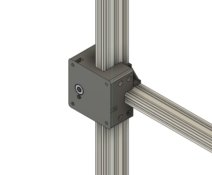
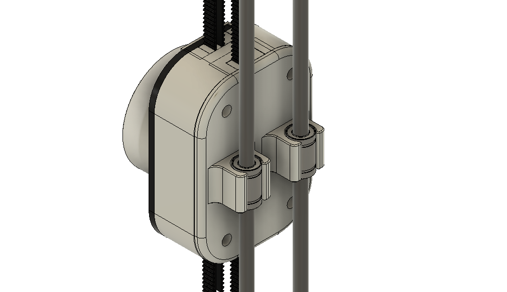
Anticipating the possibility of vibration, I had initially added holes in the design to accommodate steel rods for future reinforcement. Once the problem was confirmed, I went ahead with modifying the gantry and Z-axis. Two steel guide rods were added to provide firm structural support. The end effector was then connected to these rods using linear bearings, which significantly improved stability and motion accuracy.
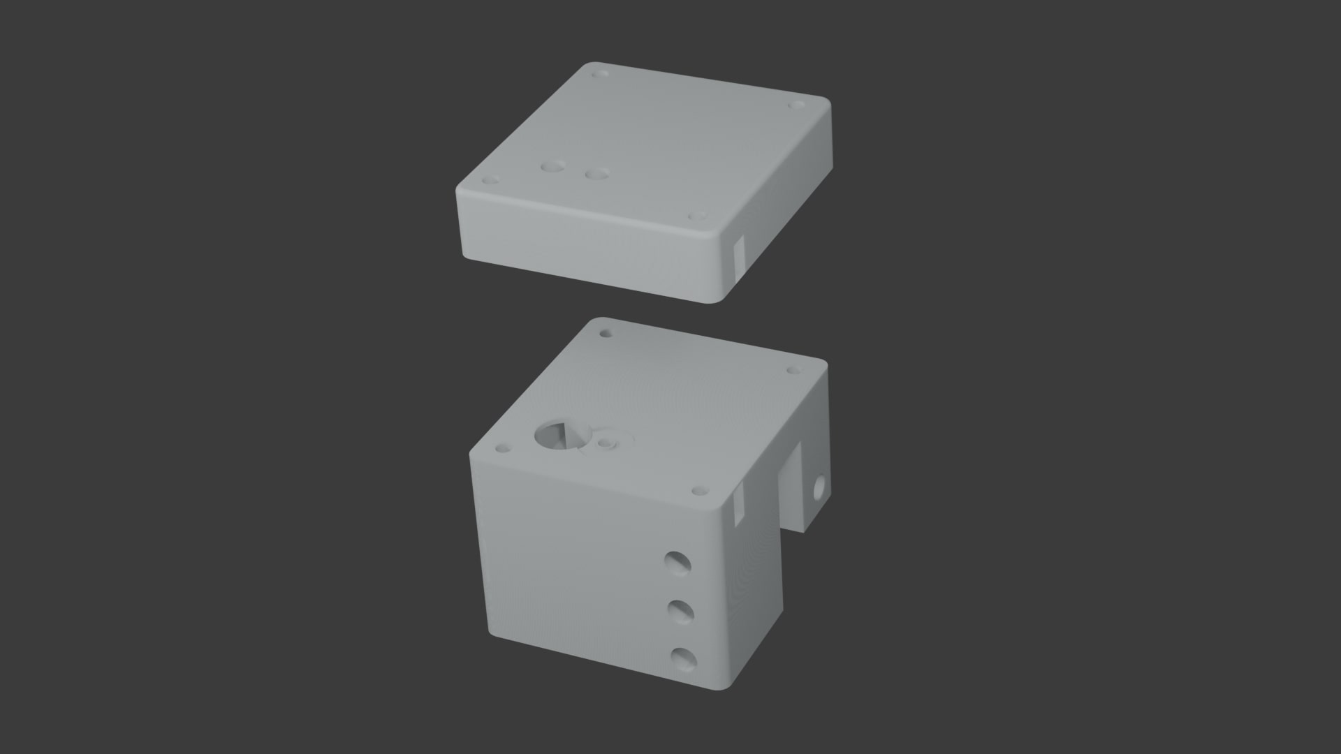
In addition to the rods and bearings, I also had to design a new component that could securely mount the end effector to the linear bearings. This ensured a tight, vibration-free fit and allowed for consistent movement along the rails. These enhancements greatly improved the machine's precision and output quality.
Below is the newly designed part that connects the end effector to the steel guide rails:
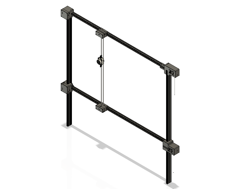
This image shows the updated design of the machine after the structural modifications were implemented:
Conclusion
the tasks that were assigned to me was completed successfully and the machine was working as intended and the pattern was captured by the camera.