
Computer Controlled Machining
This week, we learned about CNC machining, its types, and material cutting techniques. We explored the ShopBot PRSalpha 96, tested speeds, feeds, and toolpaths, and practiced safe machine operation. I designed, machined and assembled a media cabinet for my final project - Spotify Turntable to present it.
Learning Objectives
Assignments
Group Assignments
Individual Assignments
Group Assignment
This week's group assignment provided valuable hands-on experience in CNC machining safety, machine operations, and precision testing. We began with comprehensive safety training, where we learned best practices for working with CNC routers and power tools. The importance of personal protective equipment (PPE), including goggles, masks, and hearing protection, was emphasized to ensure a safe working environment. Understanding these precautions is essential for minimizing risks and operating CNC machines efficiently.
Group AssignmentBeyond safety, we explored the ShopBot PRSalpha 96 CNC router, gaining insights into its functionality, controls, and toolpath execution. Learning about speeds, feeds, and material selection helped us understand how different factors influence machining quality. By working with our CNC router, we developed a deeper appreciation for machine accuracy, proper fixturing techniques, and the importance of setup precision in achieving successful cuts.
To apply our knowledge, we designed and tested a jig for runout , pocketing, dogbones and fit assessment, allowing us to evaluate the machine's accuracy and alignment. This hands-on approach reinforced key concepts of precision machining and troubleshooting. Overall, this assignment strengthened our understanding of CNC technology, machine calibration, and safe operational procedures, preparing us for more complex CNC fabrication projects in the future.
Individual Assignments
Design, Machine and Assembly something big
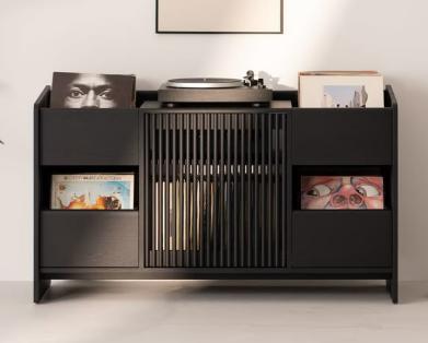
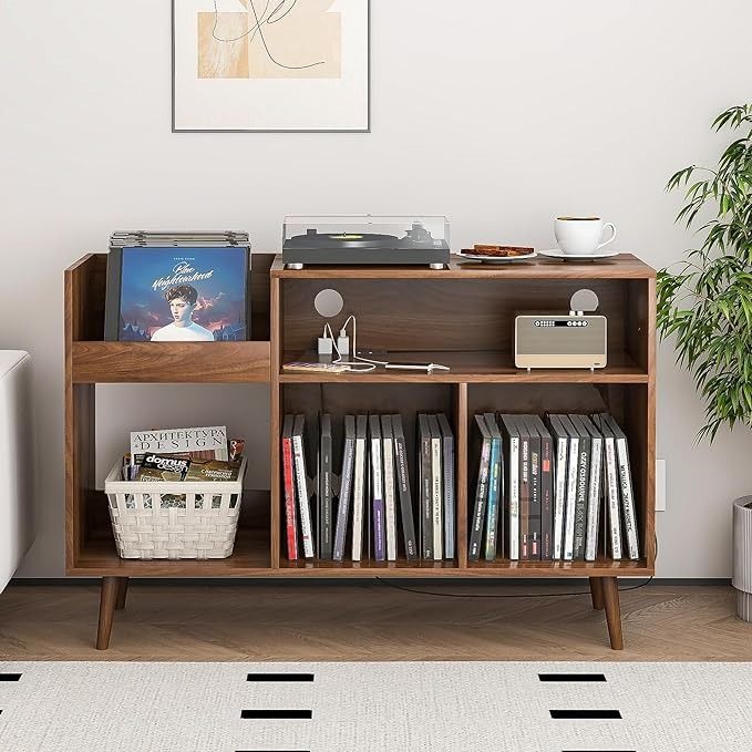
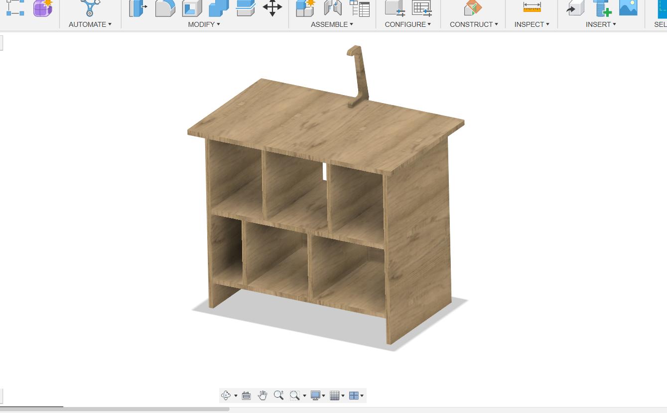
For my individual assignment, I decided to make a stand/media cabinet that could store books and records while also showcasing my final project—an NFC-based Spotify record player. I started by looking for inspiration on Pinterest, exploring different record player stands and media cabinets that could house a record player, speakers, books, and accessories. My goal was to design something that would not only be functional but also aesthetically pleasing and suited for my final project setup.
Design Process
Research & Inspiration
Before starting the design, I looked at various media cabinet designs online, particularly on Pinterest. I focused on cabinets that could efficiently store vinyl records, books, and speakers while having a dedicated space for the NFC Spotify record player. I took inspiration from minimalist designs that emphasized clean lines and modularity.
Parametric Modeling in Fusion 360
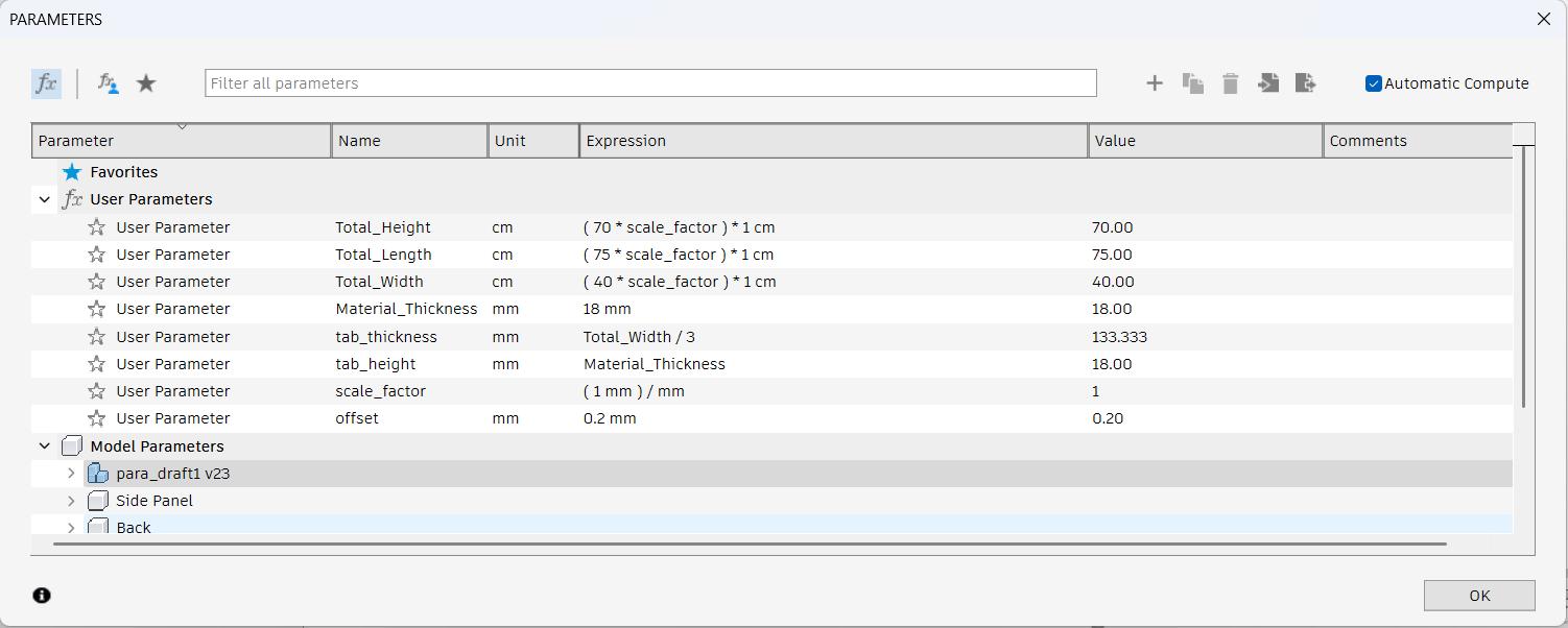
Once I had a clear vision, I started designing the cabinet in Fusion 360. Since I wanted flexibility in the dimensions, I set up a parametric model, defining key parameters such as height, length, width, and material thickness. This ensured that if I needed to make modifications, I could do so without manually adjusting each component.
Before I started designing, I watched some youtube tutorials for woodworking and design with Fusion 360 for wood working. The below youtube video was helpful for designing my media cabinet. The tutorial goes through building a bookshelf in Fusion 360. I wanted something similar for my assignment.
Fusion 360 bookshelf TutorialThe below video shows how to add cabinets parametrically, this was also very helpful
Fusion 360 Parametric Modeling Cabinet Drawers TutorialI tried to sketch the design first before jumping into the Fusion 360 CAD Design. I went through a lot iterations of the design. The design had to be aesthetcially complementing the
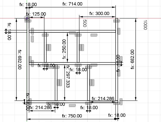
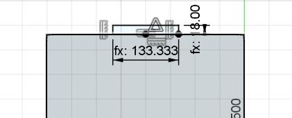
The above sketch is dimensioned using the parameters given below.
After defining the parameters, I applied constraints to ensure all parts of the cabinet were properly aligned and structurally stable. I designed the shelves and compartments to fit my intended use, making sure the spacing accommodated vinyl records, books, and audio equipment. I also planned the joint types to make assembly easier.
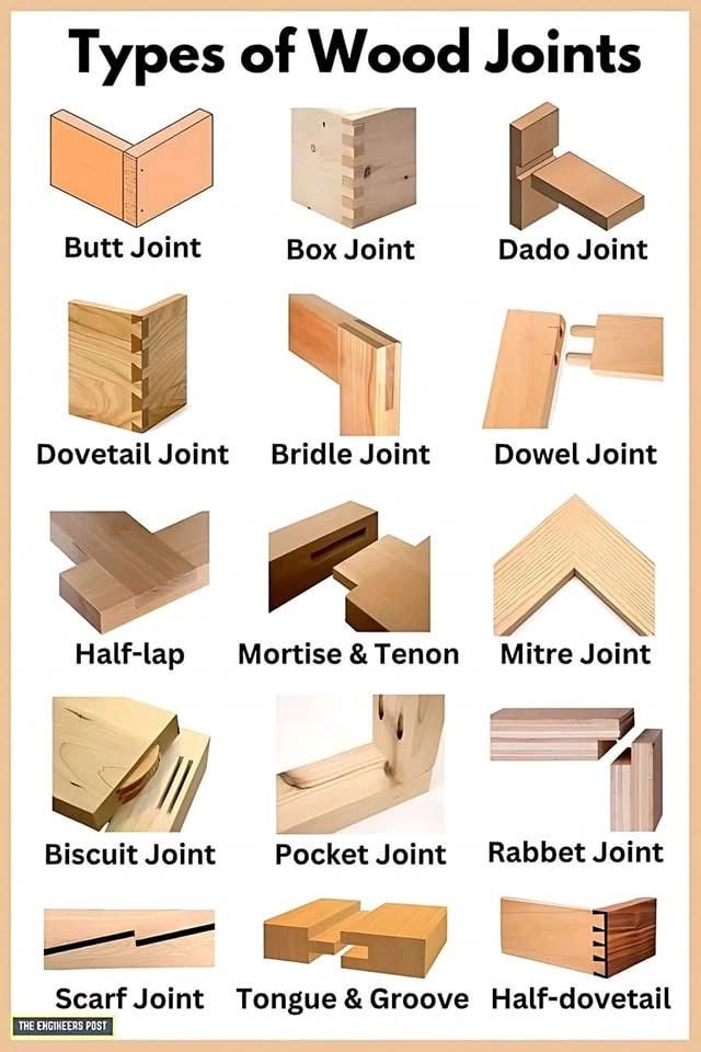
There are multiple types of wood working joints which are commonly used in carpentry. I chose to use a finger joint.
I have added slot parameters for the finger joint slots and made them. You can see the sketch for the slot in the below image.
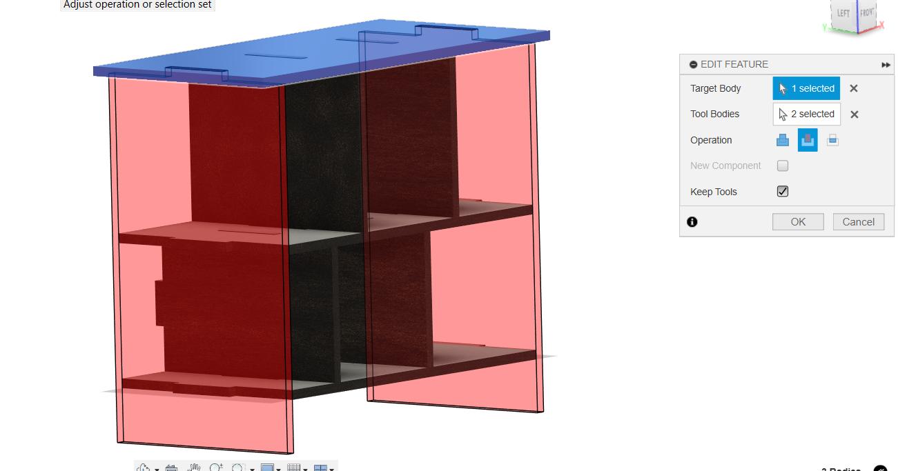
After extruding the sketch to form slots, I used the combine feature to form the negative slots in the components.
After selecting components, I arranged them on the sketch.
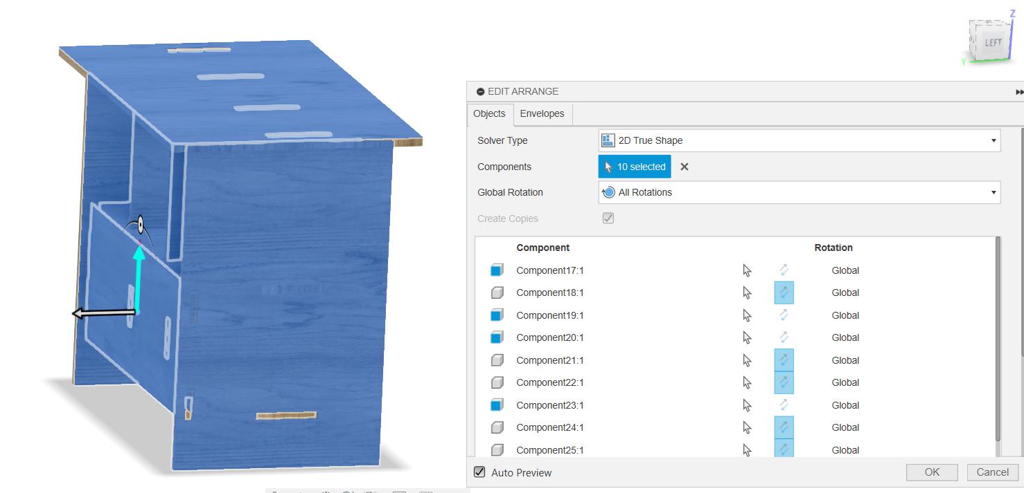
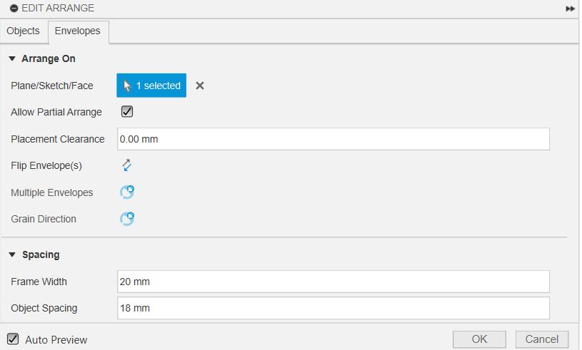
The arrange feature uses a sketch as an canvas to arrange all the components in the given area. I have used the sketch of a rectangle with the dimensions of the Plywood Sheet of 8ft x 4ft and arranged the components on them. The spacing is set to Frame Width: 20 mm and Object Spacing: 18 mm
THe below image shows all the components arranged in the given sketch Area.
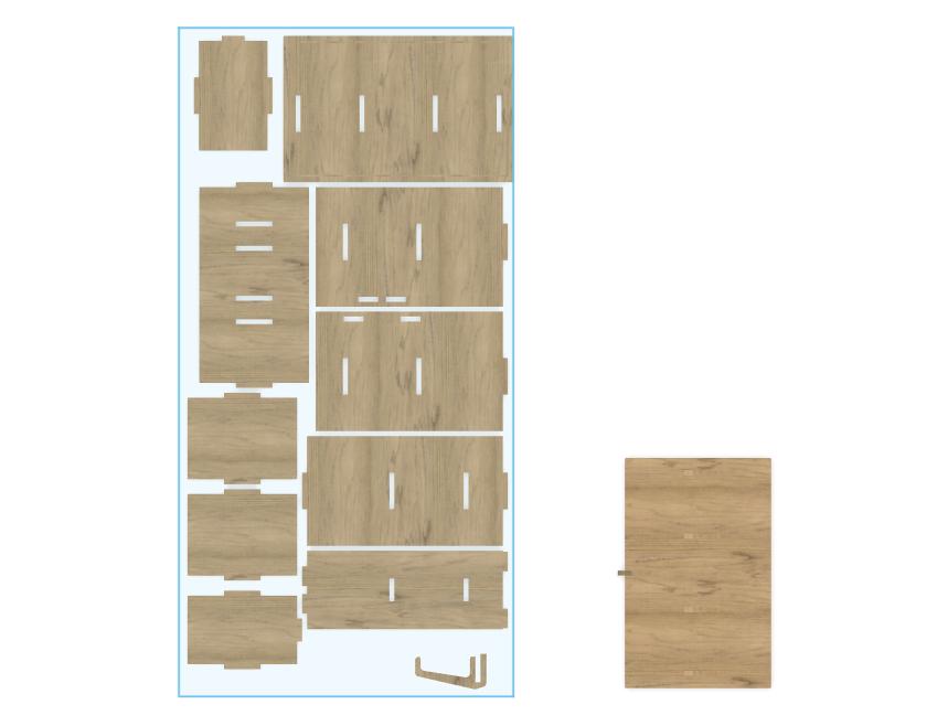
After arranging the components, I exported the components as DXF files for CNC machining. I made sure to export each component separately to ensure that they could be machined individually.
Cardboard Models before Machining Wood
For testing the look and aesthetic of the cabinet, I took the design files and edited them to cut a cardboard model of the cabinet
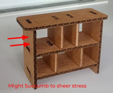
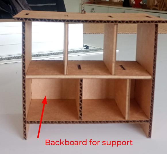
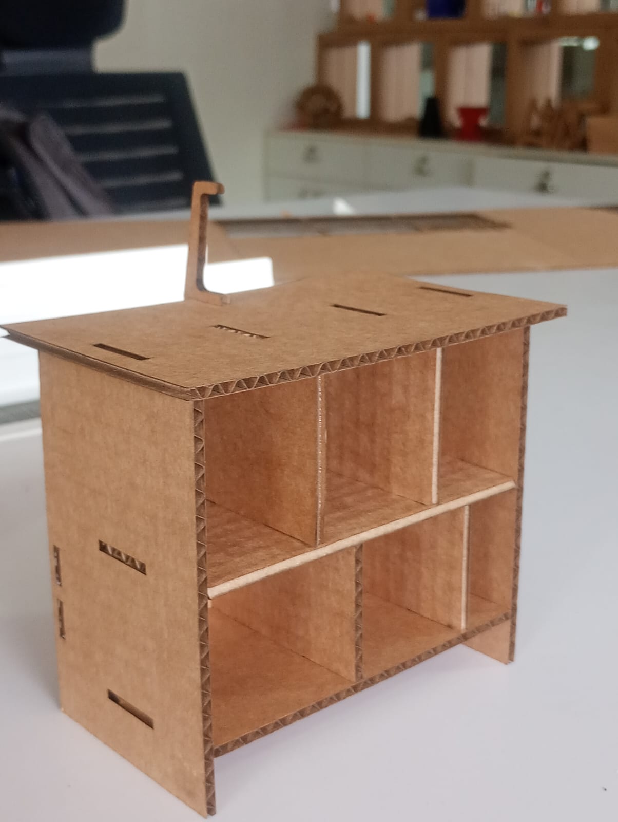
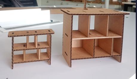
After several iterations I decide my final parameters and decide to machine the design and make my cabinet.
Computer Aided Manufacturing
VCarve Pro
VCarve Pro is a complete software solution for CNC routing, sign making and engraving. This is the software many professional sign shops and fabricators use. While the software can import your designs from other programs, it also contains a complete all the tools needed to create your designs right in the program.
After finalizing the design in Fusion 360, I exported the components as DXF files for CNC machining. I used VCarve Pro to create the toolpaths for the ShopBot CNC router. VCarve Pro allowed me to set up the material dimensions, tool settings, and cutting strategies.
In VCarve Pro, I created separate toolpaths for each component, including pocketing and profile cuts. I also added tabs to hold the parts in place during machining. The software provided a simulation feature that allowed me to visualize the machining process and check for any potential issues before sending the job to the CNC router.
CAM Setup
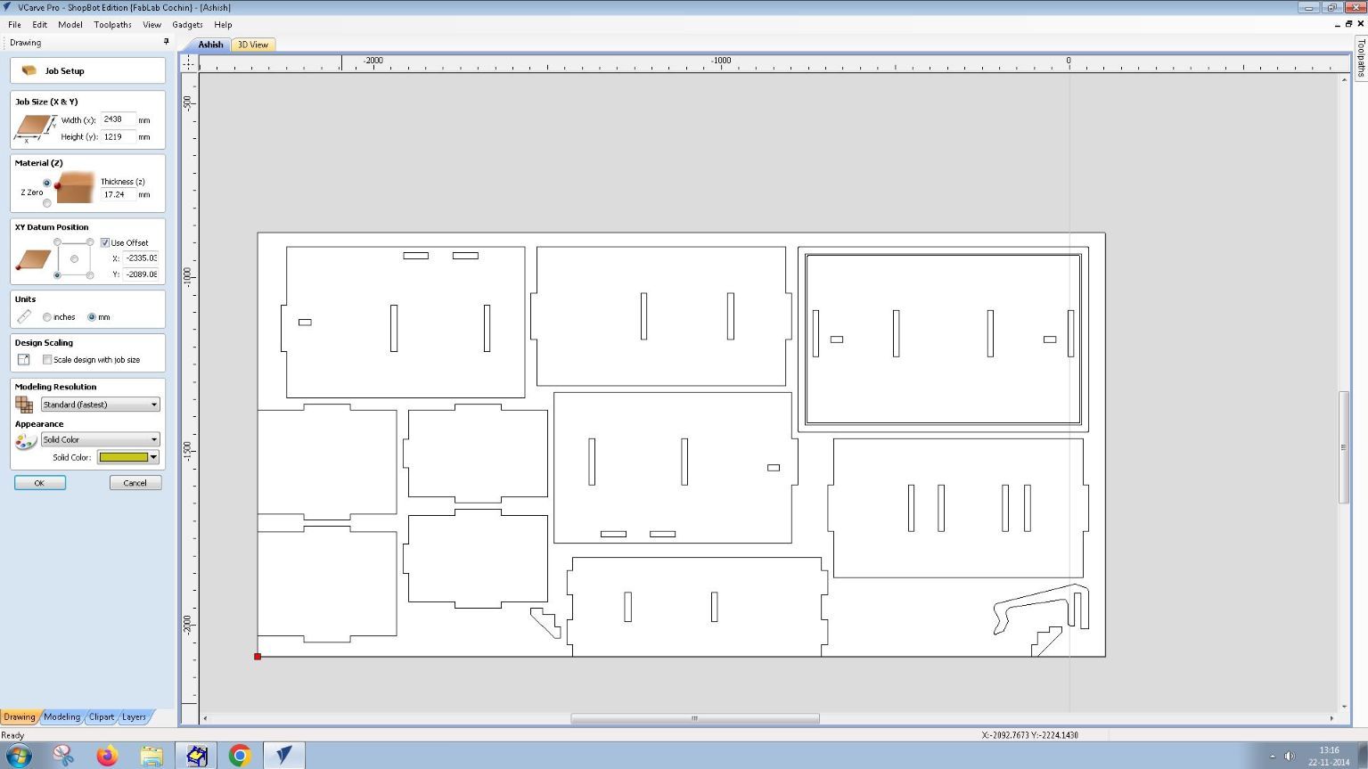
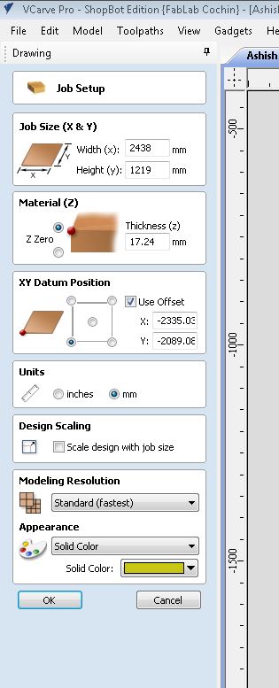
Job SetupBefore starting the CNC machining process, I had to set up the job parameters in VCarve Pro. This included defining the job size, material thickness, XY datum position, and other essential parameters. I ensured that the material dimensions matched the actual plywood stock I would be using for the cabinet.
The material that I used was the standard 8 x 4 feet 18mm Plywood Sheet available in the lab. Therefore, I entered the values as 2438mm (X Axis) x 1219mm (Y Axis) in the Job Size. After measuring with the vernier calliper I realised that the material thickness varied vastly across the board and was not 18 mm. I found the average thickness of the board to be 17.24 mm
The next step was to open the DXF files exported from Fusion 360 in VCarve Pro. I imported each component's DXF file into the software, ensuring that they were correctly aligned and positioned within the job area. You can select all the elements of the DXF and press M to move them inside the job canvas by using the Arrow Keys.
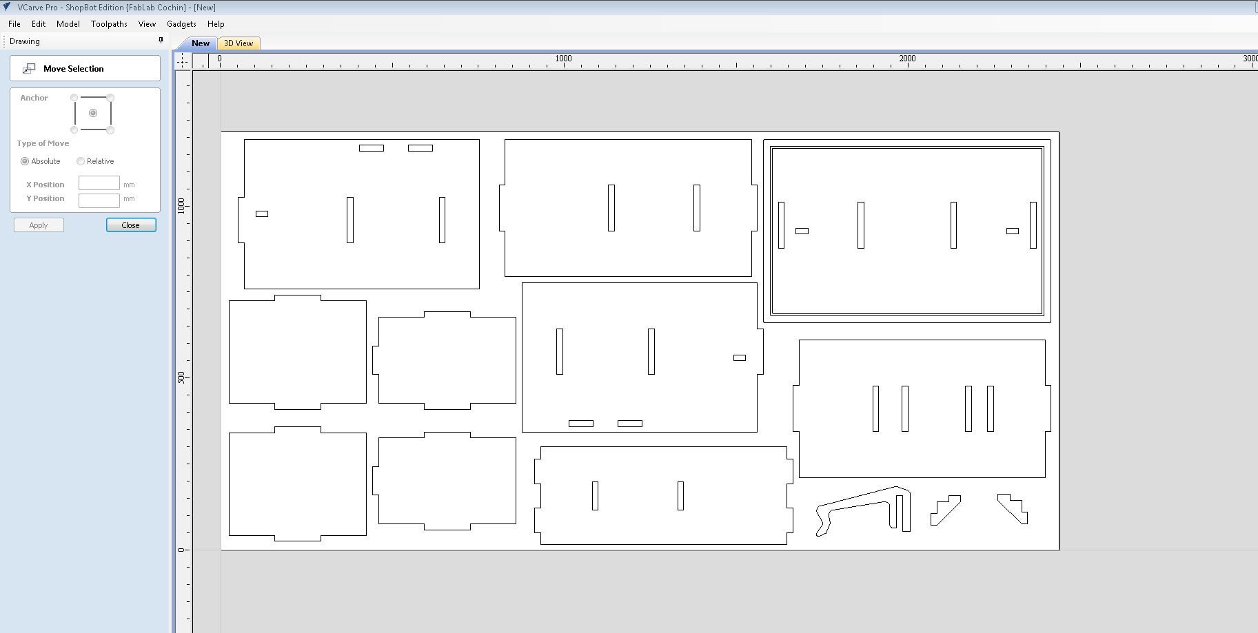
Remember always to complete a operation and exit from the operation after you are done, to use other features. You need to finish the job setup to be able to select the elements in the file.
This is where you can select different vectors and edit them. The tools on the left side of the window help you to edit and add features to the existing vectors.
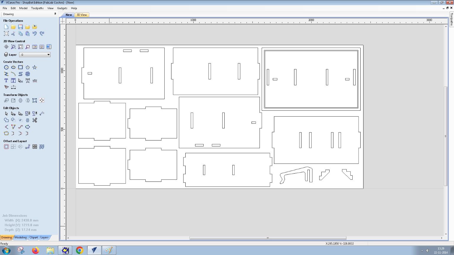
On the right side of the window there is the toolpath tab to generate, edit and manipulate toolpaths.
Drilling Toolpath
Before machining the stock, we need to fix the workpiece/stock on the machine bed firmly. So we will pre drill some holes or placeholders for drilling and screwing the work piece on the bed.
The toolpath generator for drilling can be found in the toolpaths window on the right. We have to select the drilling toolpath and select the tool for drilling.
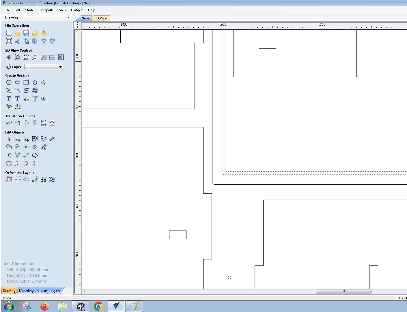
Before starting, we need to add circles in the vector file to generate paths for drilling. To add circles you have to choose the 'Create Vectors' option and select Circles and place them in areas where you want to drill. Make sure they are not too close to the cutting lines and placed well enough to hold the piece firmly to the bed.
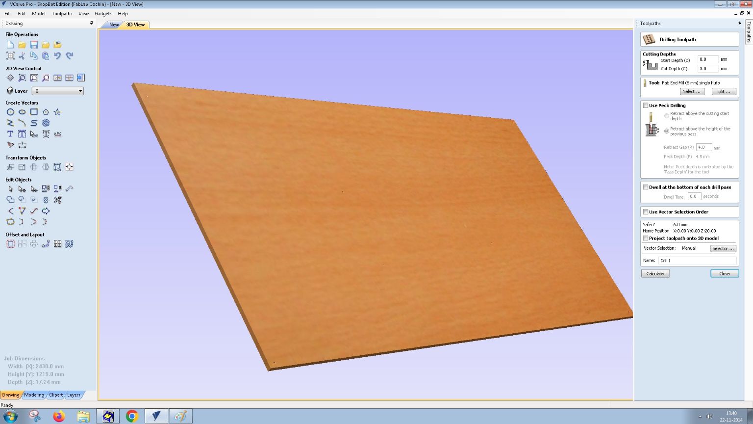
You can see all the necessary parameters needed for the drilling toolpath
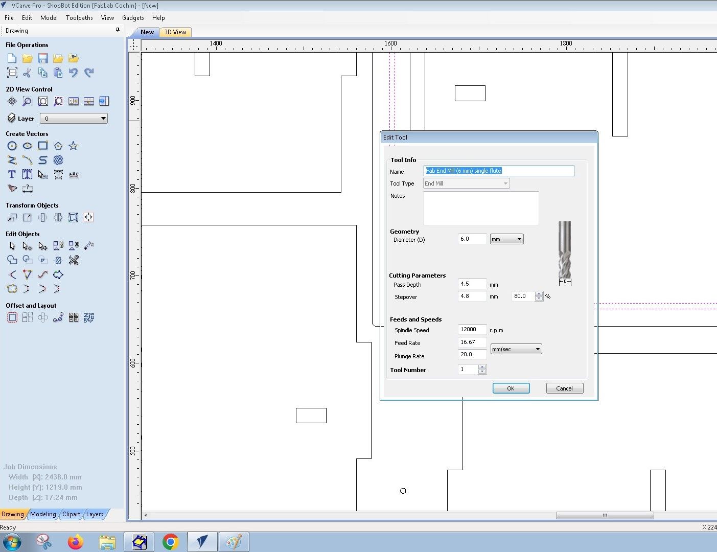
After adding the necessary circles, we need to select them and generate the toolpath for them. We have to choose parameters like tool,etc before generating the toolpath. We'll be using the Fab End Mill 6 mm Single Flute Tool .
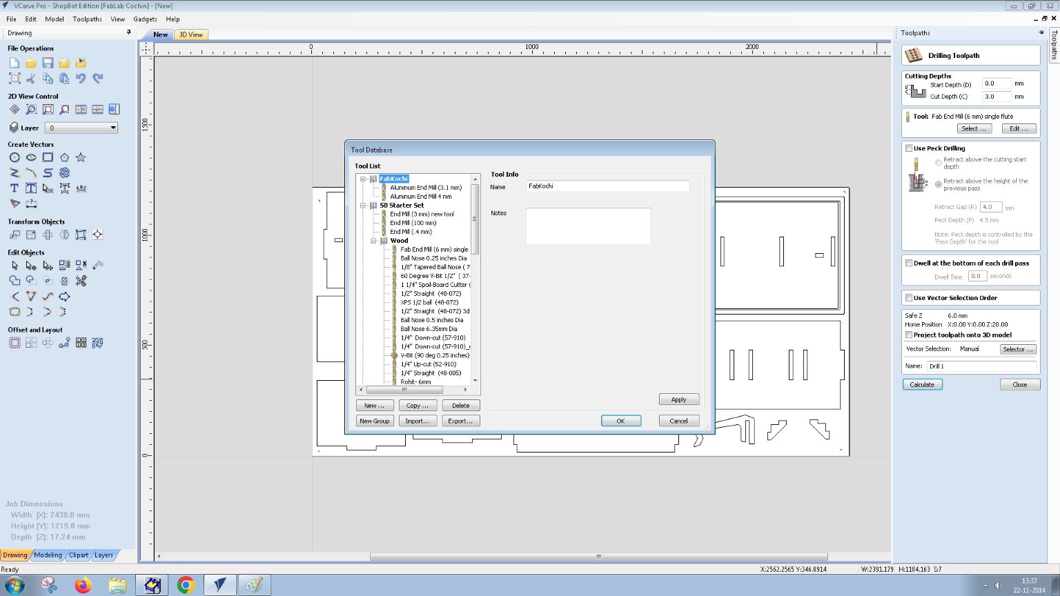
We can edit the tool properties by selecting the edit option below the tool on the right side window. For our case we'll make sure the feeds, speeds and cutting parameters are set according to the tool and the workpiece.
After adding the necessary parameters for the toolpath we can claculate the toolpath and preview it. We can preview all the existing toolpaths or just the individual toolpath and watch a simulation of the toolpath on the workpiece.
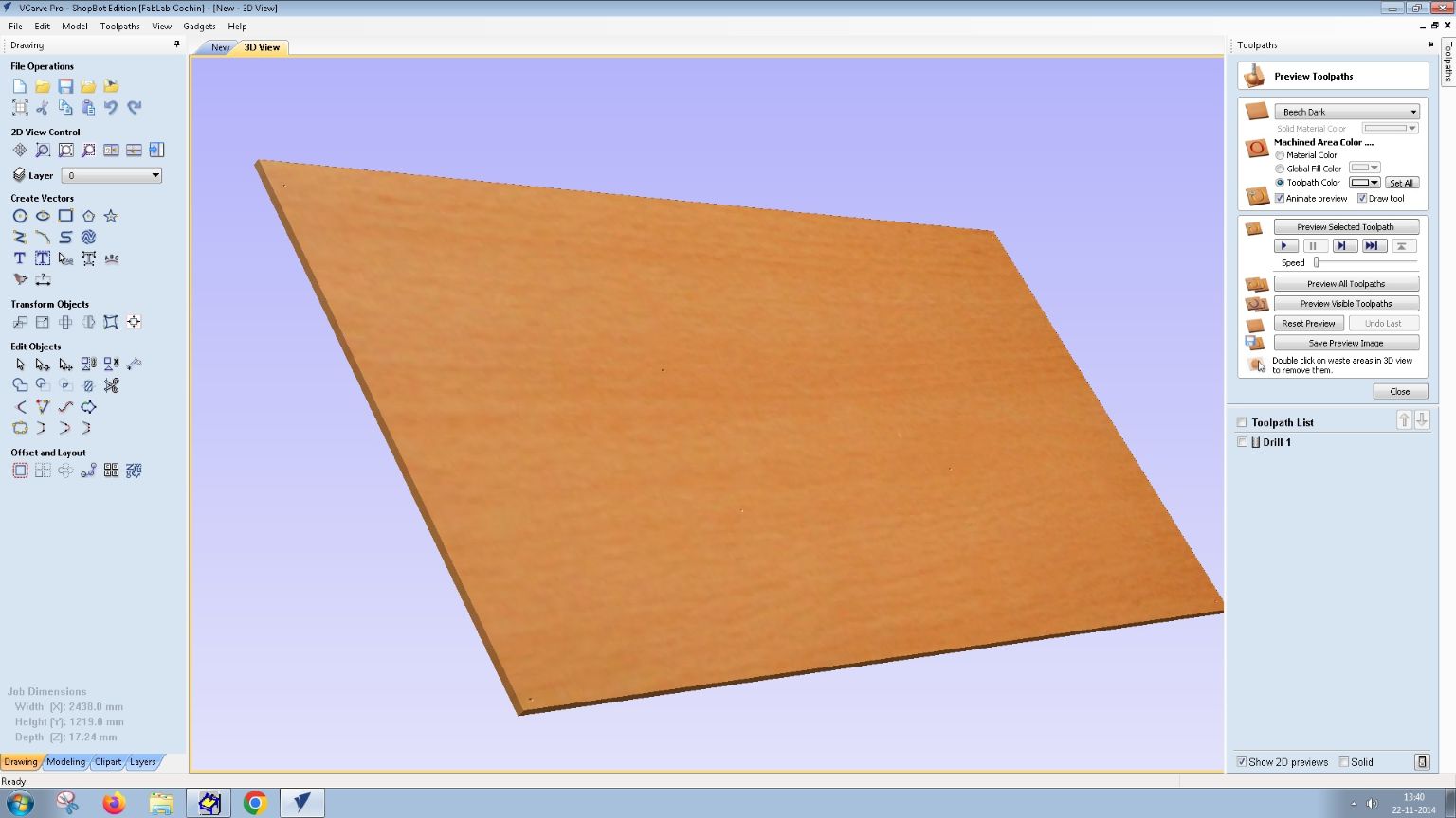
The drilling toolpath is ready.
Pocket Toolpath
The next step is to create the pocket toolpath for the cutouts in the cabinet. The pocket toolpath will define how the CNC router will cut out the shapes from the plywood stock. In VCarve Pro, you can select the 'Pocket Toolpath' option in the toolpaths window.
We need to select the vectors that we want to cut out and then choose the appropriate tool for the pocket cut. For our case, we'll use the Fab End Mill 6 mm Single Flute Tool again. We can set the cutting depth, feed rate, and other parameters based on the material and tool specifications.
Dogbones are small notches or grooves that are added to the corners of a cutout to allow for the thickness of the cutting tool. They ensure that the corners of the cutout are rounded, which is essential for proper assembly and fitting of parts.
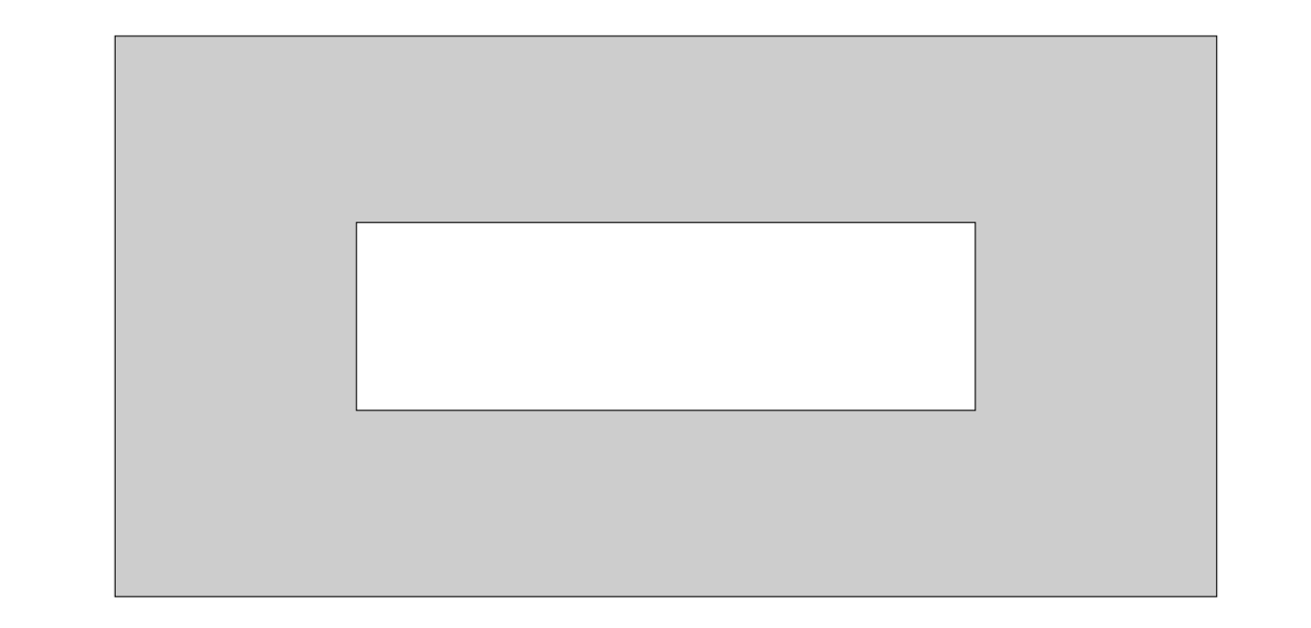
Photo credit: CNC Madness
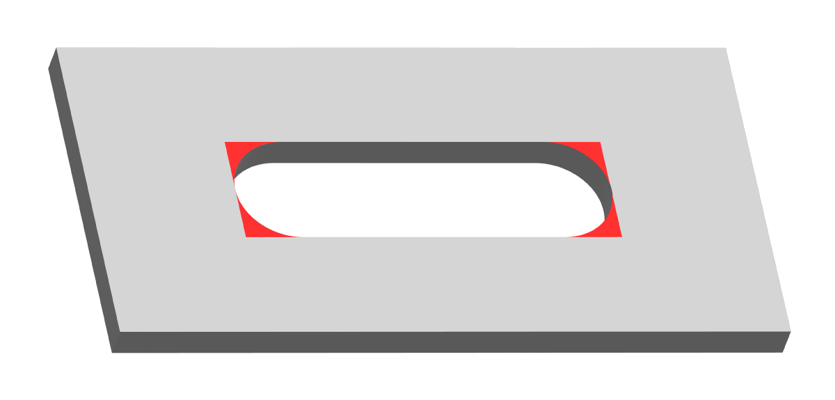
Photo credit: CNC Madness
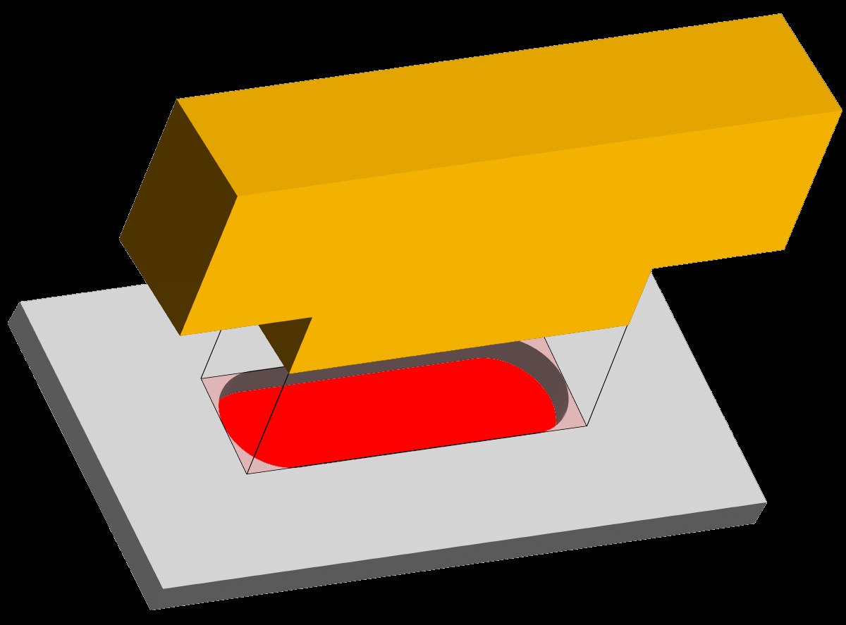
Photo credit: CNC Madness
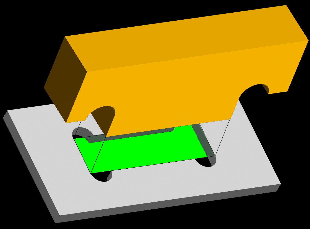
Photo credit: CNC Madness
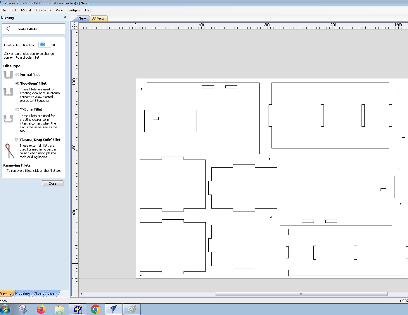
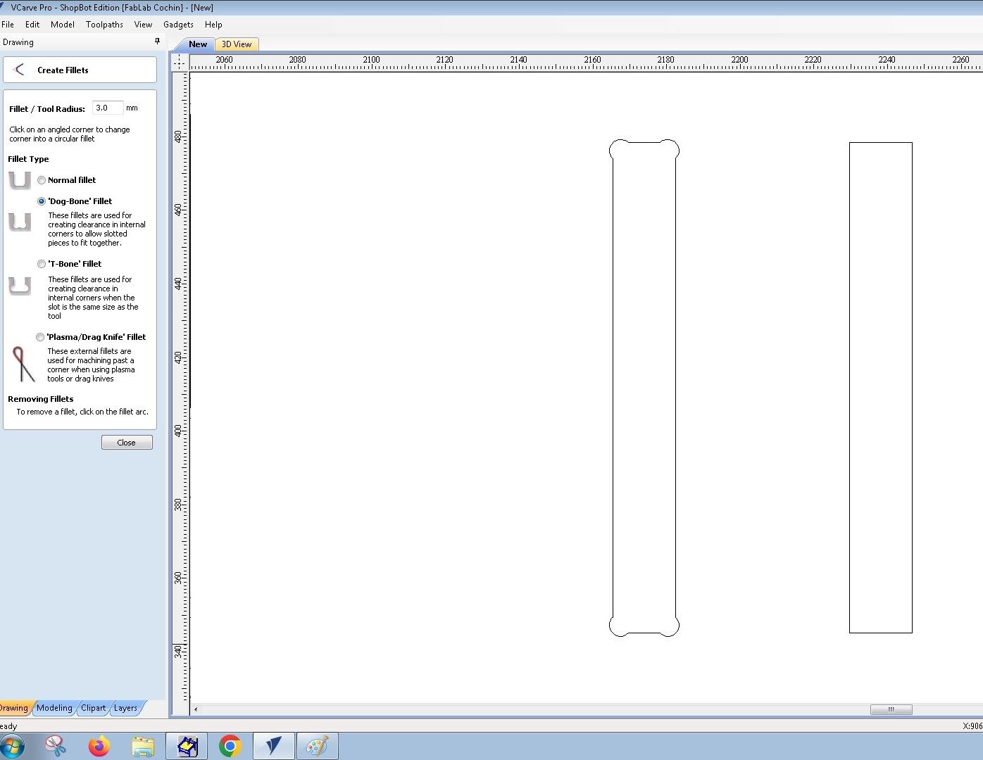
In VCarve Pro, you can add dogbones by selecting the 'Dogbone Fillet' option in the 'Create Fillet' option in 'Edit Objects' menu.
2D Profile Toolpath
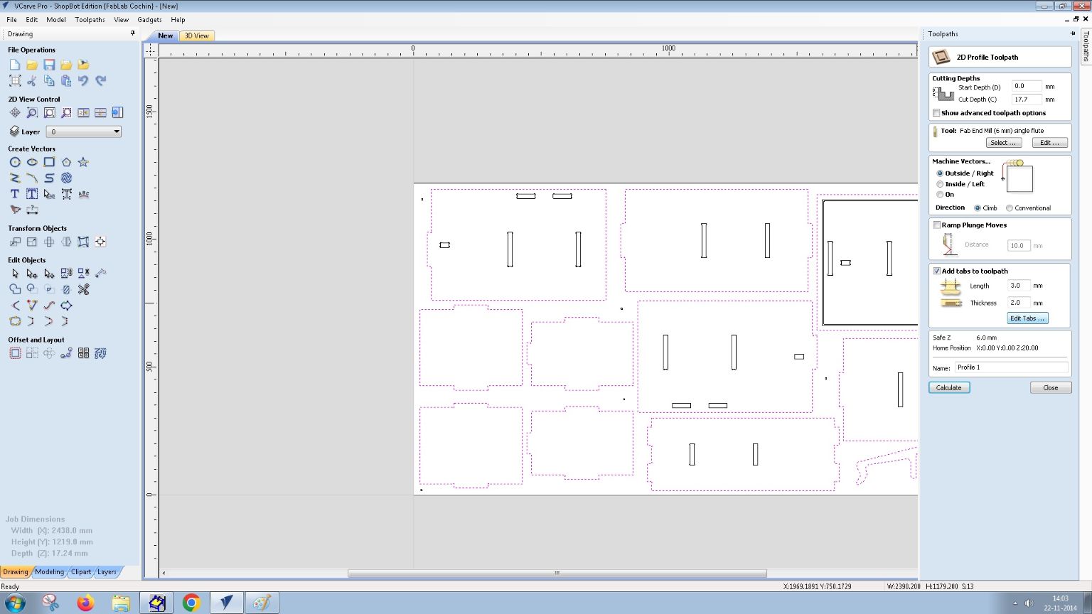
After adding the dogbones, we need to create the 2D profile toolpath for the actual cutting of the components. This toolpath will define how the CNC router will cut out the shapes from the plywood stock. In VCarve Pro, you can select the 'Profile Toolpath' option in the toolpaths window.
What are tabsTabs are small bridges that are left uncut in the material to hold the cut pieces in place during machining. They prevent the pieces from moving freely and ensure that they remain attached to the stock until the machining is complete. Tabs are essential for maintaining the integrity of the workpiece and preventing it from shifting during cutting.
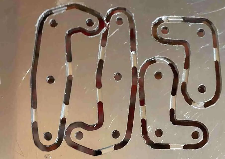
Photo credit: Glue It
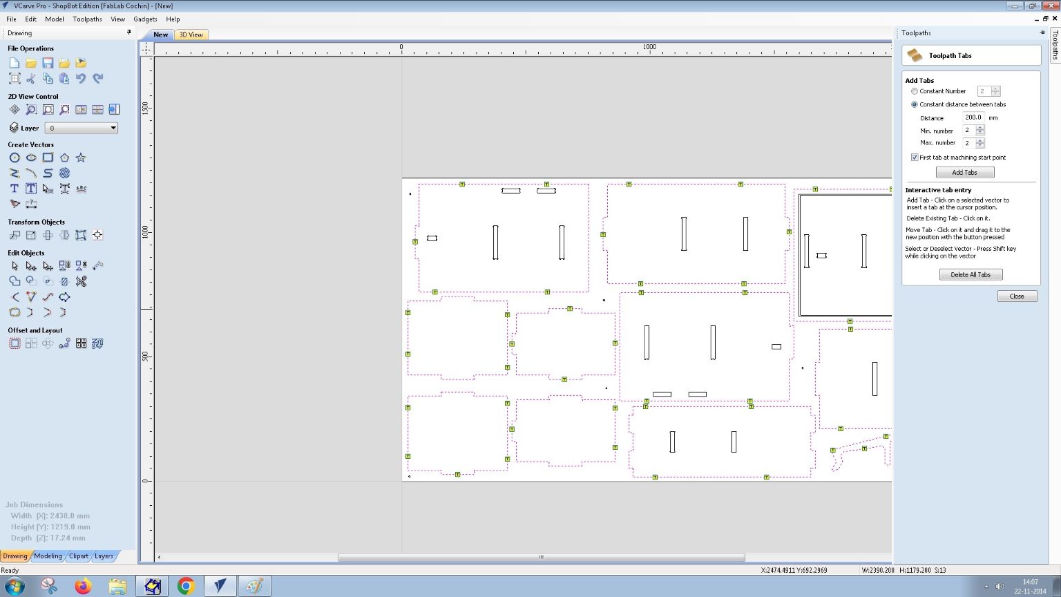
In VCarve Pro, you can add tabs by selecting the 'Add Tabs to Toolpath' option in the profile toolpath settings. You can specify the size of the tabs and then select 'Edit Tabs' to add tab points
You can select the 'Add Tabs' to add the points. The below image shows with all the necesaary tabs.
We need to select the vectors that we want to cut out and then choose the appropriate tool for the profile cut. For our case, we'll use the Fab End Mill 6 mm Single Flute Tool again. We can set the cutting depth, feed rate, and other parameters based on the material and tool specifications.
After setting the parameters, we can calculate the toolpath and preview it to ensure everything looks correct. The simulation will show how the CNC router will cut out the shapes from the plywood stock, including the dogbones and any other features we added.
You can select all the toolpaths generated int Toolpath list
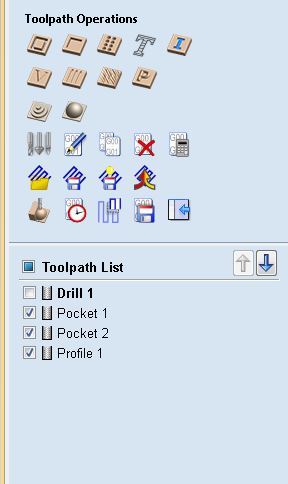
Once all the toolpaths are set up and previewed, we can save them as G-code files. G-code is the language that CNC machines understand, and it contains instructions for the machine to follow during the cutting process. In VCarve Pro, you can select the 'Save Toolpath' option and choose the appropriate post-processor for the ShopBot CNC router.

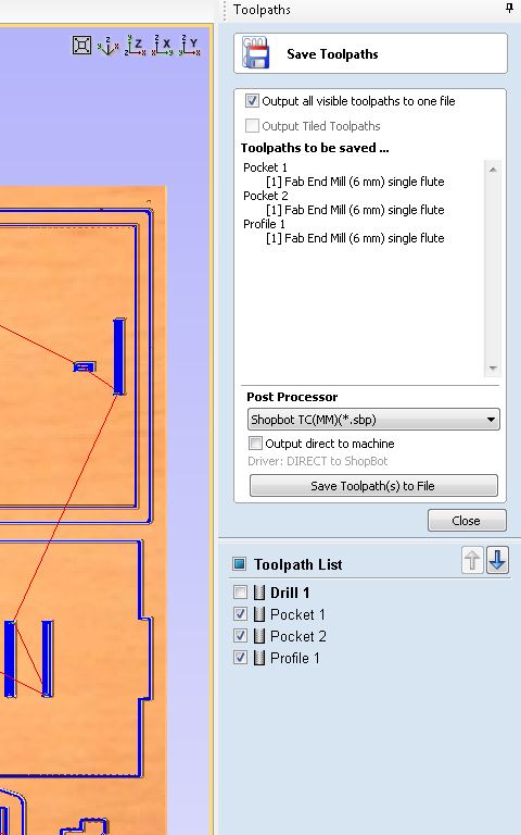
You have to save the toolpaths individually as GCODE files. The drill toolpath needs to be saved and ran individually before all the machining, as we need to screw the Plywood Sheet on the bed. The other 3 toolpaths can be saved together as they use the same tool.
ShopBot CNC SoftwareWe have to open the ShopBot CNC Software and aopen the .sbp file generated by VCarve Pro and load in the software. After opening the post processesed file we need to select 'Cut Part' button to cut the part.

CNC Machining
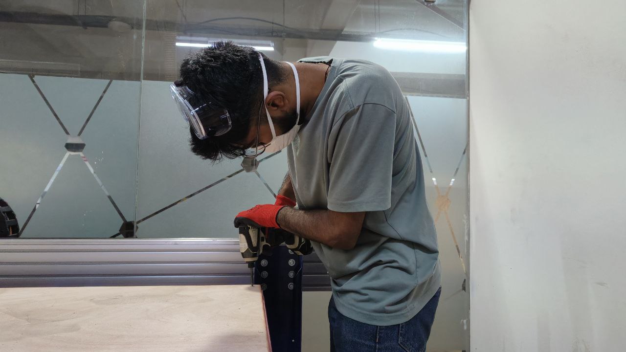
First the drill holes/placeholders are drilled by the ShopBot CNC. After the drilling, I manually screwed into the predrilled holes using the Bosch Drill Set.
After screwing the workpiece on the bed. I ran the rest of the toolpaths using the ShopBot CNC software.
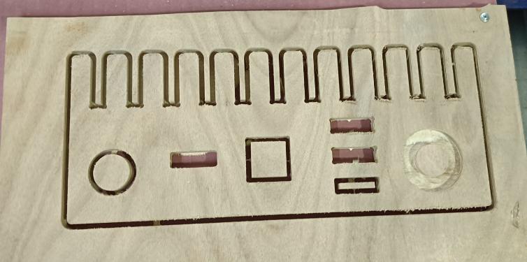
The above timelapse shows the CNC Cutting of the piece
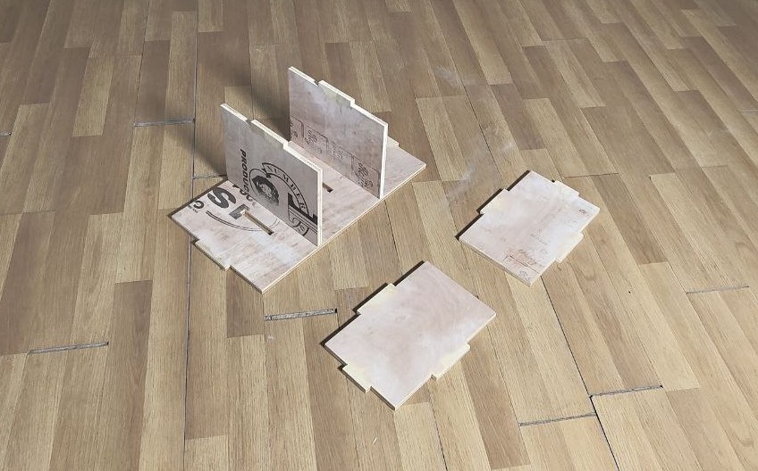
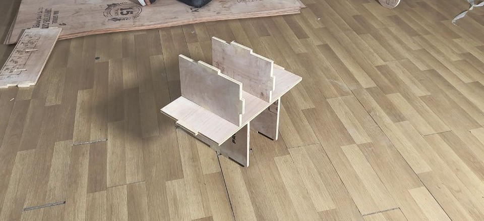
Assembly
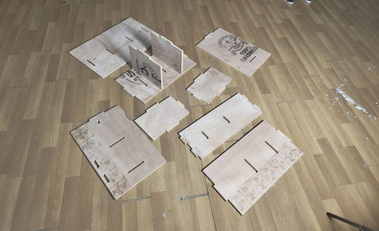
After the CNC Machining was complete, I assembled the cabinet pieces together. The finger joint design allowed for easy assembly without the need for additional fasteners or glue. The assembly process was straightforward, and the precision of the CNC cuts ensured a snug fit for all components.
The cabinet was assembled with the help of my fellow classmates Revishankar, Noel and instructor Saheen during a overnight assembly process.
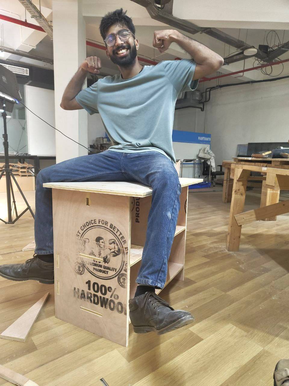
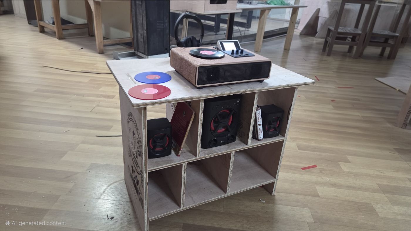
The below picture is of my final project Symphoni placed on my cabinet.
Design Files
You can download my design files from below
Fusion 360 File
Step File