
3D Scanning and Printing
This week, I explored 3D Scanning and Printing, using Rhino and Grasshopper for voronoi design and Fusion 360 for tight-tolerance parts. I worked with Polycam on iPhone for photogrammetry and Artec Leo for structured light scanning, refining scan data for CAD integration. This hands-on experience improved my understanding of mesh optimization, scan accuracy, and additive manufacturing constraints.
Learning Objectives
Assignments
Group Assignments
Individual Assignments
Group Assignment
In this week's group assignment, we explored slicing software, which converts 3D models into layer-by-layer instructions for a 3D printer. A slicer takes a 3D design (STL, OBJ, or 3MF), generates toolpaths, and outputs G-code, which dictates print head movements, extrusion rates, and speeds. It allows fine control over parameters like layer height, infill density, supports, and print speed, ensuring optimal print quality and material efficiency.
I used Bambu Studio, an advanced slicer tailored for Bambu Lab 3D printers, though it also supports generic printers. Bambu Studio features an intuitive interface and powerful options like variable layer heights, tree supports, organic infills, and automatic part orientation. It also integrates AI-based flow compensation and multi-material support for seamless multi-color printing. Additionally, real-time print monitoring via Bambu Handy enhances user control over prints.
Through hands-on testing, we adjusted key slicing parameters such as wall thickness, retraction settings, cooling, and adaptive layers to balance speed and precision. Comparing different infill patterns and support structures, we analyzed how slicing strategies impact strength, print time, and material usage. This exercise provided deeper insight into how slicers bridge the gap between 3D design and physical fabrication, ensuring efficient and high-quality prints.
The group assignment can be found on this link
Individual Assignments
Design and 3D print an object that could not be easily made subtractively
For this week's 3D printing assignment, I explored Voronoi patterns and collapsible mechanisms, experimenting with different tools and design approaches. I wanted to design something that could not be fabricated using subtractive manufacturing, making use of complex internal structures and print-in-place mechanisms.
Designing in Grasshopper
I started by exploring Voronoi patterns, which are organic, cell-like divisions commonly used in computational design. Voronoi patterns are widely used in architecture, product design, and generative art because they resemble natural cellular structures, making them aesthetically pleasing and functionally lightweight.
Rhino (Rhinoceros 3D)
Rhino is a NURBS-based 3D modeling software commonly used in industrial design, architecture, and computational design. Unlike traditional solid modeling (Fusion 360, SolidWorks), Rhino allows freeform surface modeling, making it ideal for complex, organic designs. You can download Rhinoceros 3D for a trial period of 90 days from their website.
Grasshopper
Grasshopper is a visual programming language inside Rhino. Instead of writing code, it allows designers to create algorithms using nodes. This is useful for parametric modeling, where designs can be easily modified by adjusting input values.
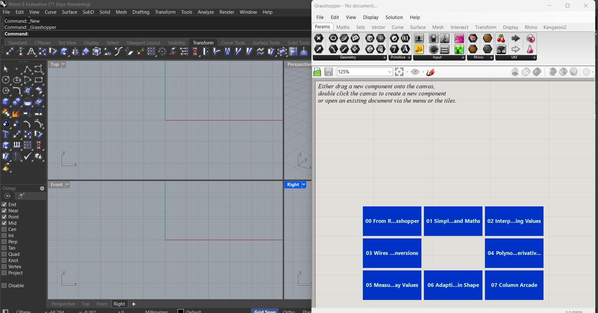
My initial approach was to use Grasshopper in Rhino. However, I found the interface to be overwhelming, as it required precise control over point distributions, cell sizes, and constraints.
Despite the complexity, I was able to generate:
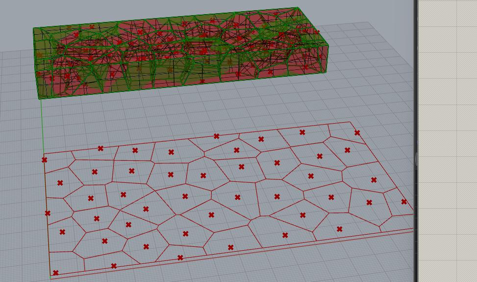
A 2D Voronoi pattern that could be used as a surface texture.
A 3D Voronoi structure, creating a lattice-like pattern inside a solid body.
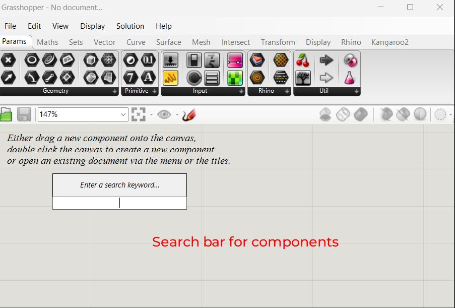
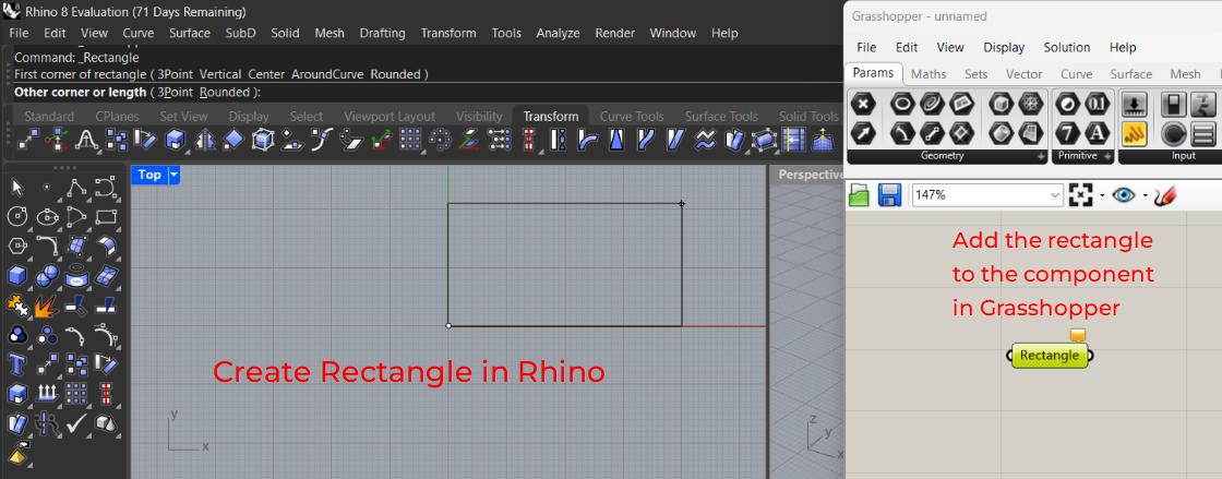
In Grasshopper you can look up for components in the search bar by double clickin anywhere on the grasshopper workspace
Designing a 2D Voronoi Pattern
- Setting up the Rectangle
Voronoi 2D and 3D - Populating the 2D Space with Random Points
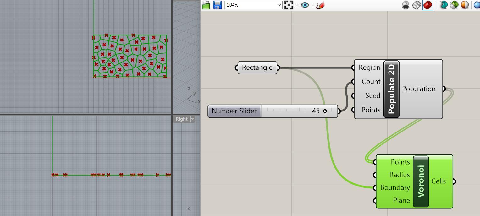
Voronoi 2D and 3D - Generating the Voronoi Diagram
Voronoi 2D and 3D - Baking the Voronoi Pattern into Rhino
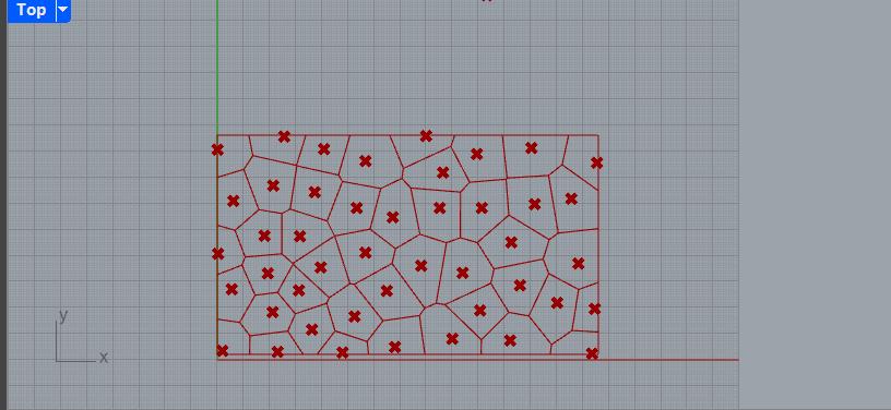
Voronoi 2D and 3D
Designing a 3D Voronoi Pattern
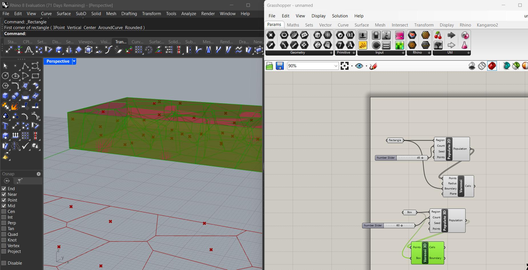
- Creating a 3D Bounding Box
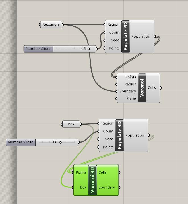
Instead of a 2D rectangle, start by creating a Box using the Box component
- Populating the 3D Space with Points
Use the Populate 3D node (from the Vector → Grid tab) to distribute random points inside the box.
- Generating a 3D Voronoi Diagram
Connect the output of Populate 3D to the Voronoi 3D node
- Intersecting the Voronoi Structure with the Box
Voronoi 2D and 3D - Baking the pattern box
Right-click the final Voronoi output and choose Bake. This converts the generated 3D Voronoi lattice into a Rhino solid.
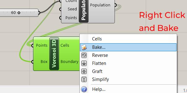
Voronoi 2D and 3D
Since I was not yet comfortable with fully parametric modeling, I decided to shift to Fusion 360, where I found a more straightforward way to generate Voronoi patterns.
Designing in Fusion 360
In Fusion 360, I used a 2D Voronoi Sketch Generator, which allowed me to easily generate randomized Voronoi structures without the complexity of Grasshopper. I then:
Embossed the pattern onto flat surfaces of a 3D model.
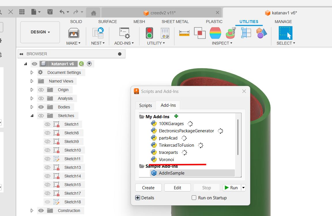
The voronoi pattern is generated by an add-in called the voronoi sketch generator which can be downloaded as a zip file from github page. The read me file will guide you through the installation process.
After the add-in is succesfully addded in the Autodesk Fusion 360 Add-ins page you can run it
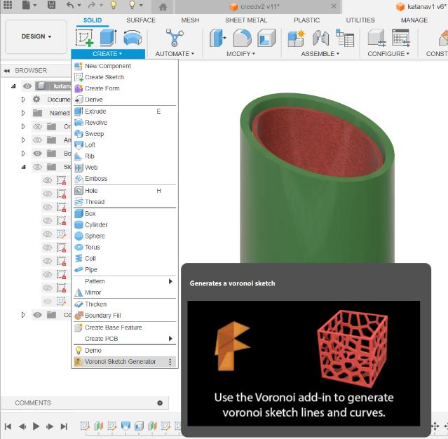
The add in is succesfully running and can be obtained from the create tab.
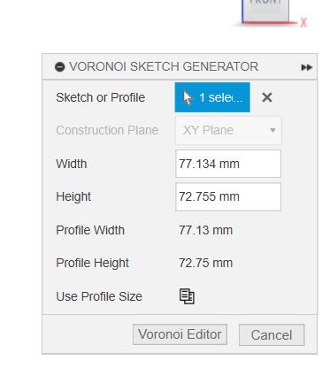
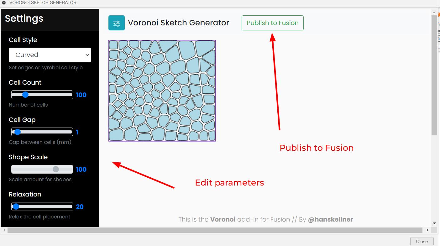
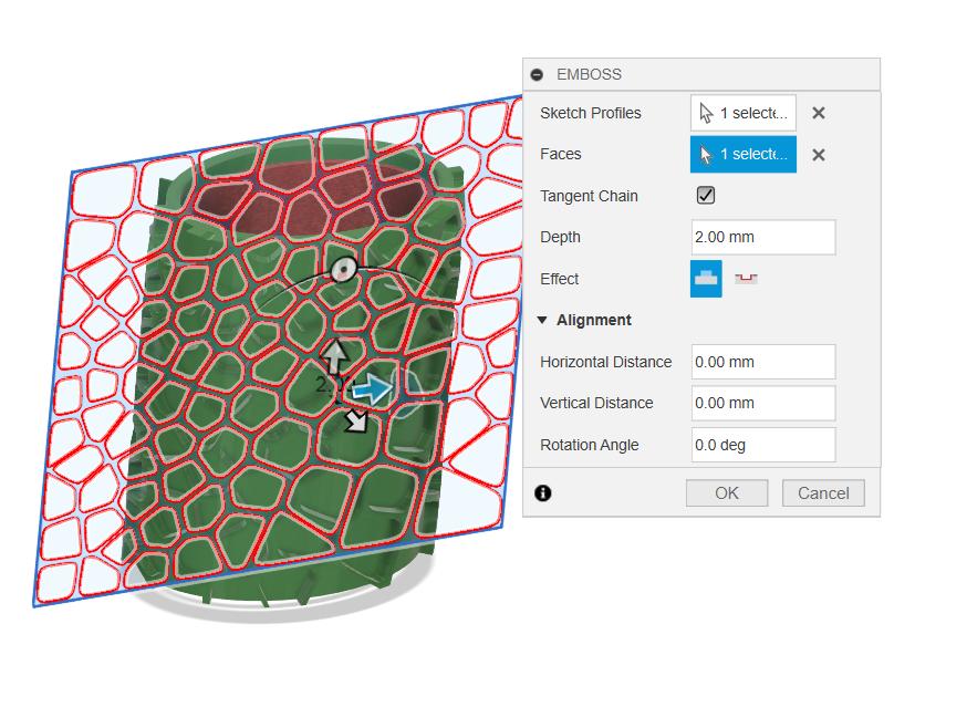
The pattern needs a sketch object. here I have made a rectangle and selected it as the surface and then select the voronoi editor. the editr allows to play with multiple parameters such as cell density, cell gap, shapes,etc.
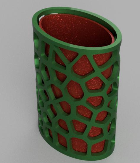
After the pattern is generated, the emboss feature is used to imprint the pattern on the target surface, the target surfacre here is the curved cylinder face. The pattern cab be either embosed or debosed
Therefore, I learned to add voronoi pattern in Fusion 360.
The Assignment Design
So I wanted to make something in print in place that's when I came acrros the collapsable katana print in place 3d print. I found it to be really cool design and doesn't require much bed volume
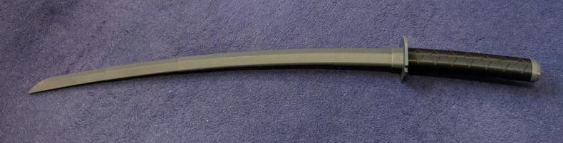
The collapsible katana has a curved shape and a telescopic nature. At first thought I thought there was a stopper at the end of each section of the katana. So I downloaded the STl file from this link
.
The above ddesign has stoppers to stop the parts from falling.
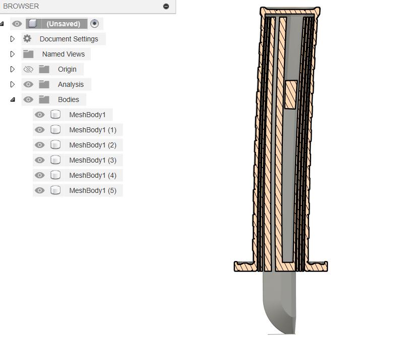
I imported the STL file in Fusion 360 and conerted it into a body using the conert mesh. After converting into a body, I used a section analysis tool to see the inner parts of the katana. The body is in a compressed format.
But after printing I realised that the clearance that i gave was more and I didn't check if the sections were touching in section analysis. The above video shows how the fit failed.
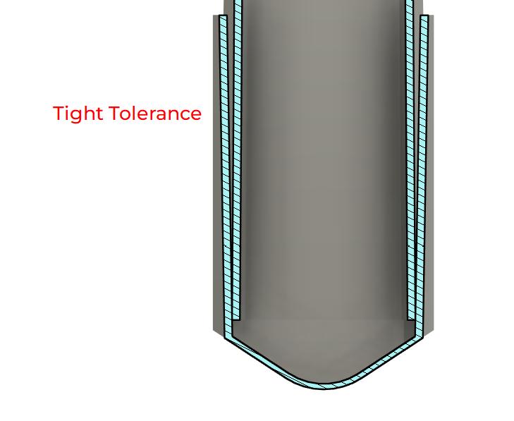
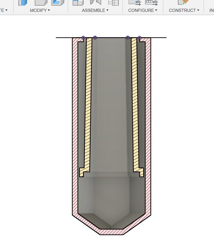
I realised that I need to make the sections tapered and don't need to add stoppers to it. I designed a test section to check if the fit is proper
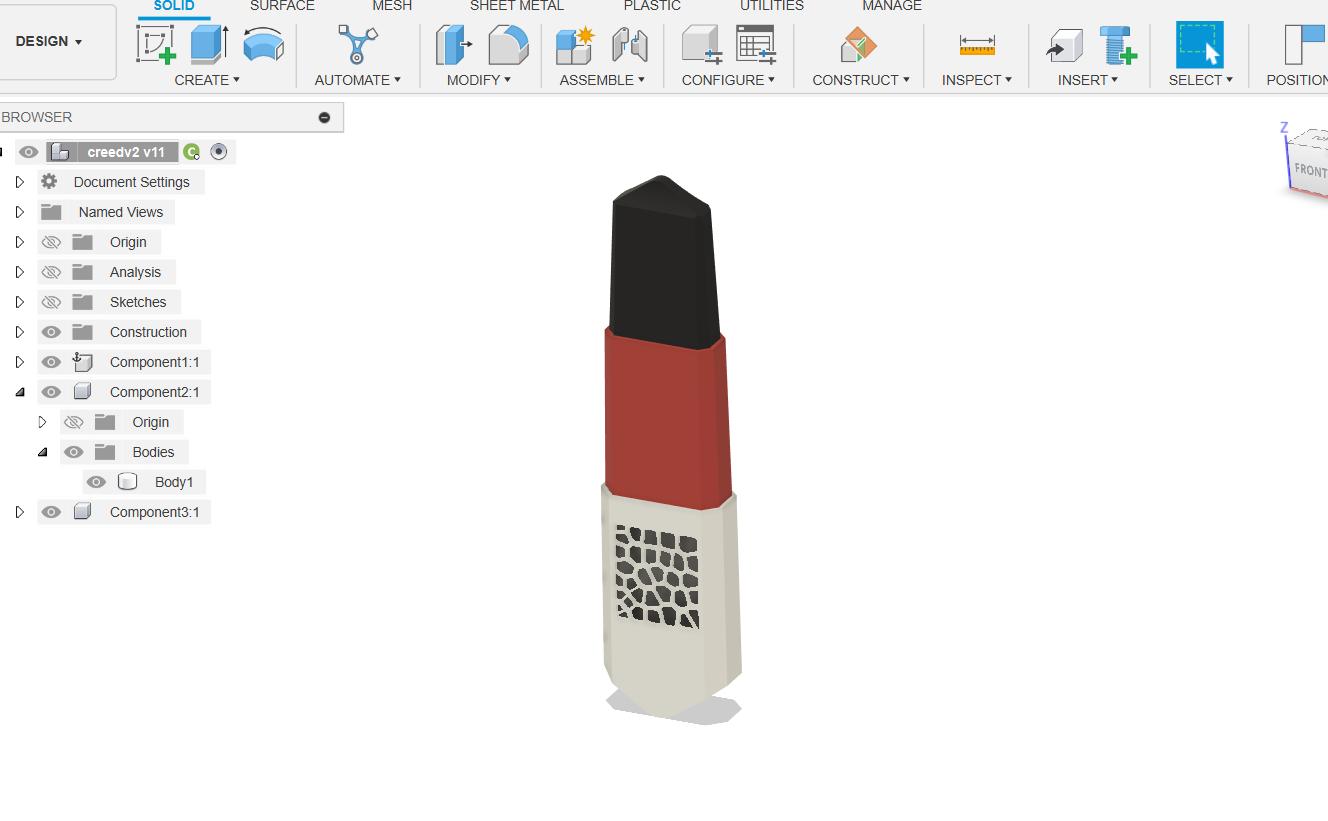
This is the final design of the blade
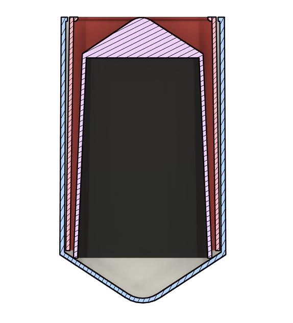
The cross section of the blade. It shows how the sections are tapered. The tapered sections proved to fail, that's why I added a lip to the bottom sections.
The above design is the final design of the collapsable blade. Now I had to export it as an STL file for 3D Printing.
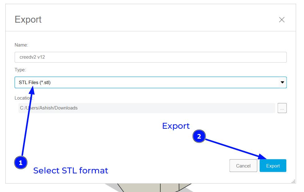
Exporting as STLTo export the design as an STL file, I used the Export function in Fusion 360.


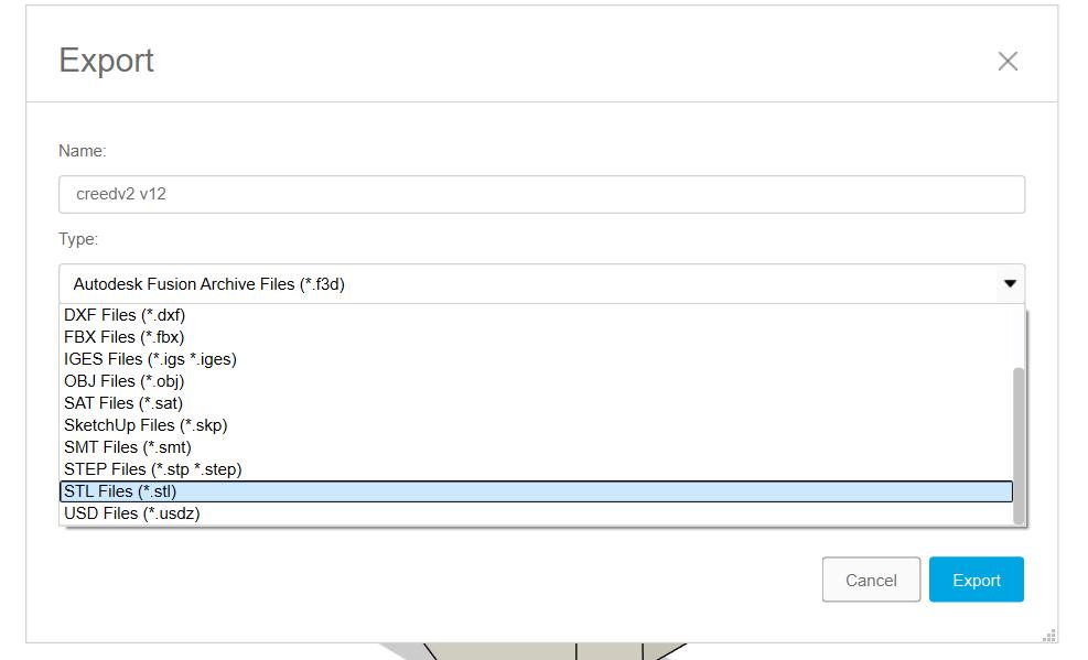
In the Export dialog, I selected the STL file format.
After exporting the design as an STL file, I opened it in Bambu Studio for slicing.
Bambu Studio
I used Bambu Studio to slice the model. Bambu Studio is a slicer software developed by Bambu Lab, specifically designed for their 3D printers. It offers advanced features like adaptive layer heights, tree supports, and organic infills, making it suitable for complex prints.
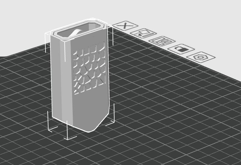
I opened the STL file exported from Fusion 360 in Bambu Studio
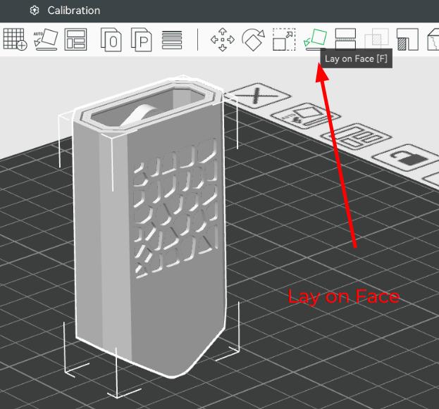
The model needs to be inverted for printing. The Lay on the Face is used to select the face on which to lay the model
Printing Parameters
I used the following printing parameters for the print:
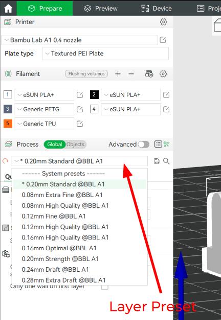
I used the Layer Preset of 0.20mm Standard for my print. You can choose from an options of presets varying from as thin as 0.08 mm to 0.28 mm layer height.
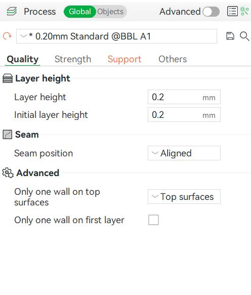
QualityThe Quality Tab consists of mainly Layer height, Seam and some Advanced Features.I used the standard layer height of 0.2mm and left the other values as default.
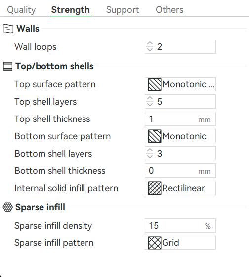
The Strength Tab consists of Infill, Wall and Top/Bottom Shell parameters. I used the standard Wall Loops 2. I used a Grid Infill with a density of 15%. The wall thickness is set to 1.2mm and the top thickness is set to 1 mm and bottom shell thickness to 0. These values ensure a good balance between strength and print time.
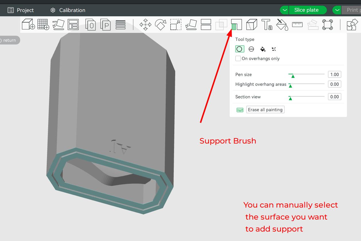
When the model is inverted, there are several overhanging parts especially the blade tip. But if we select the Normal(Auto), the slicer adds a support to all overhanging parts, even inside the model which is not favourable for the print.
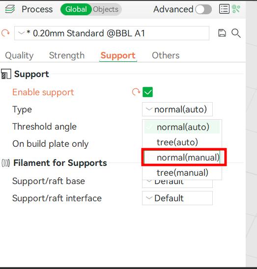
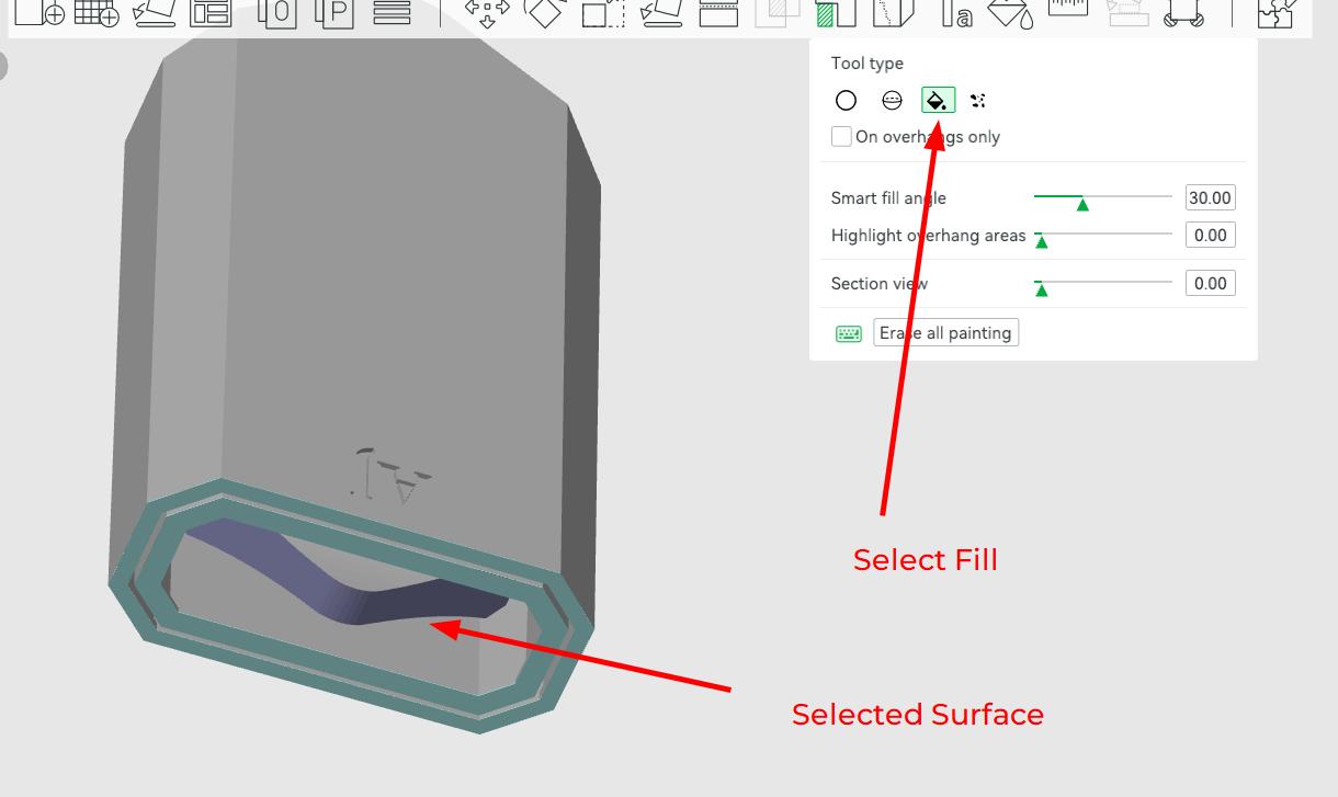
I selected the Normal(Manual) type and it allows to only add support ata specified areas
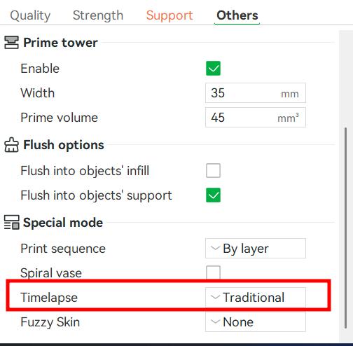
The Others tab includes things like Prime Tower, Flush Options and Speacial Mode. We can get the 3D printing Timelapse, a fuzzy skin texture, adjust the print sequence, etc. I left the options as they were.
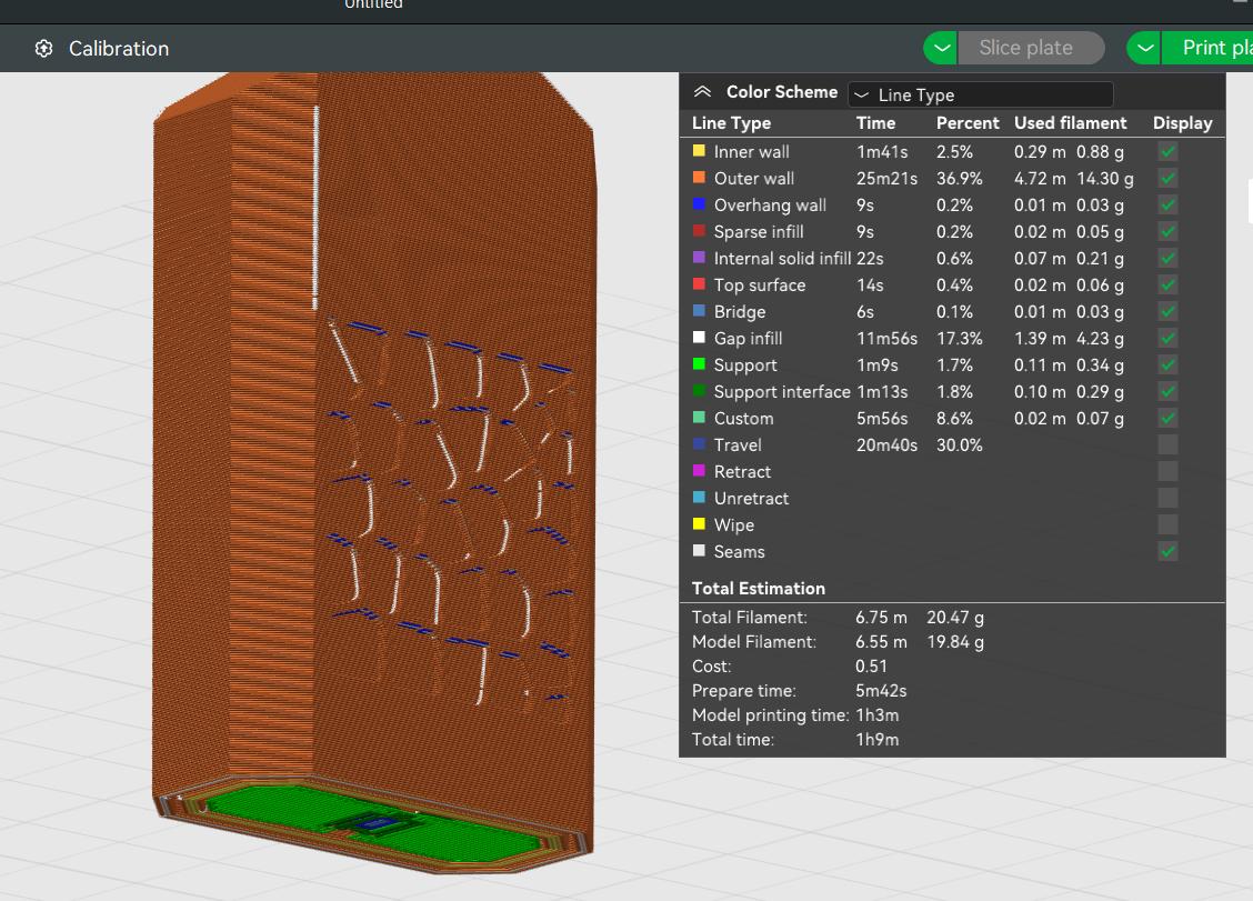
After setting all the parameters I ssliced the model and the below photo shows the time required to print the model and the color scheme helps to understand what part takes how much time individually in the whole 3D Printing process. The prepare time and model printing time, and material usage is alos mentioned in this.
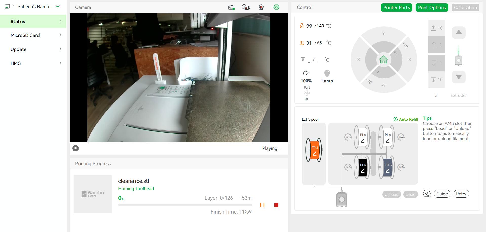
After slicing the model, I sent the 3MF file to the Bambu Lab A1 Printer. The Device Page looks the image given below. You can see the print plate using the onboard camera and also control parameters like heating bed temprerature, cooling fan speed, light, etc.
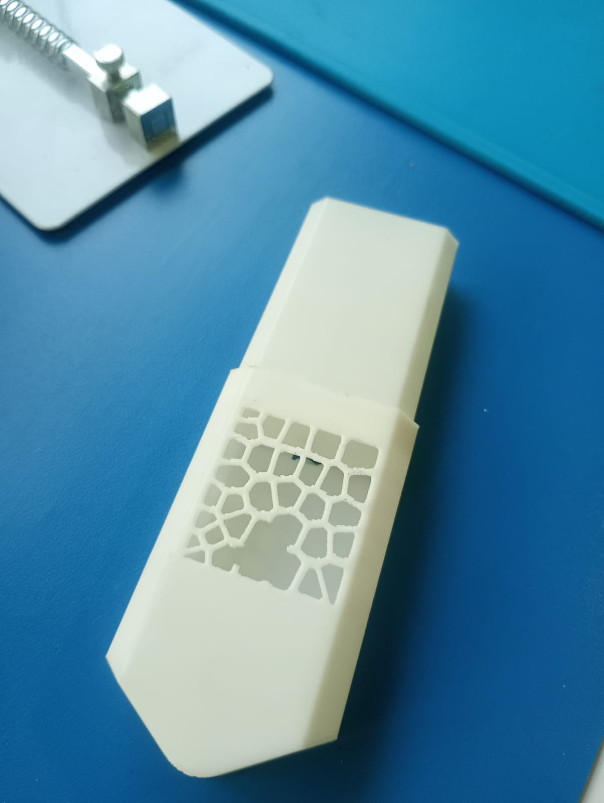
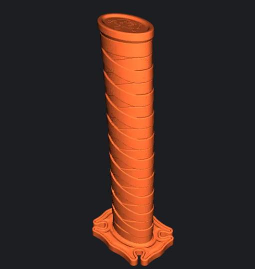
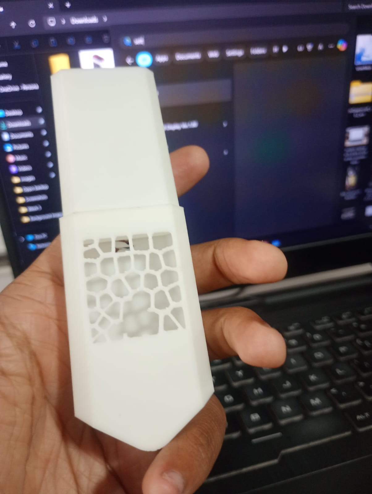
The output of 3D Printing looks like this. You can see that the voronoi pattern is broken in the front. I accidentally broke that while removing the supports.
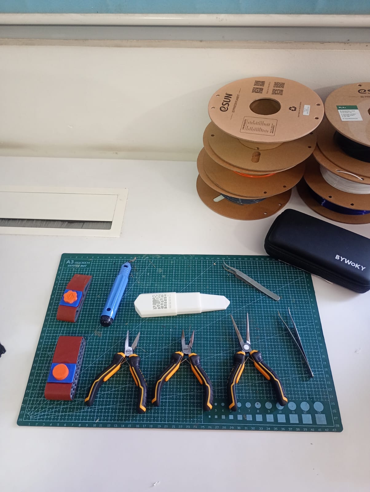
The post processing is done in the post processing area deddicated to it. I used nose pliers, sand paper and tweezers to finish the 3D Print.
The below video shows the collapsable nature of the blade.
3D Scan an object
What is 3D Scanning
3D scanning is a process of analyzing an object from the real world, to collect all the data in order to recreate its shape and appearance, digitally.3D Laser Scanning is a non-contact, non-destructive technology that digitally captures the shape of physical objects using a line of laser light. 3D laser scanners create "point clouds" of data from the surface of an object. In other words, 3D laser scanning is a way to capture a physical object's exact size and shape into the computer world as a digital 3-dimensional representation.
3D laser scanners measure fine details and capture free-form shapes to quickly generate highly accurate point clouds. 3D laser scanning is ideally suited to the measurement and inspection of contoured surfaces and complex geometries which require massive amounts of data for their accurate description and where doing this is impractical with the use of traditional measurement methods or a touch probe.
Types of 3D Scanning Technologies
To ensure flexibility in my design, I used the Modify Parameters tool in Fusion 360. I created and assigned key parameters to control dimensions dynamically:
- Laser 3D Scanning
- Laser triangulation 3D scanning technology
In this technology, the laser scanner projects a laser beam on a surface and measures the deformation of the laser ray.
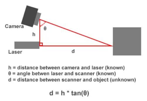
Laser Triangulation Triangulation-based laser scanners operate by emitting laser light onto an object and capturing reflected light with an onboard camera sensor. The system calculates the distance to the object using trigonometric triangulation, forming a triangle between the laser source, the sensor, and the reflected target on the object's surface. Typically used for short-range applications (less than 5 meters), triangulation scanners excel at capturing small to medium-sized objects, ranging from 1 cm to about 2-3 meters
- Laser pulse 3D scanning technology
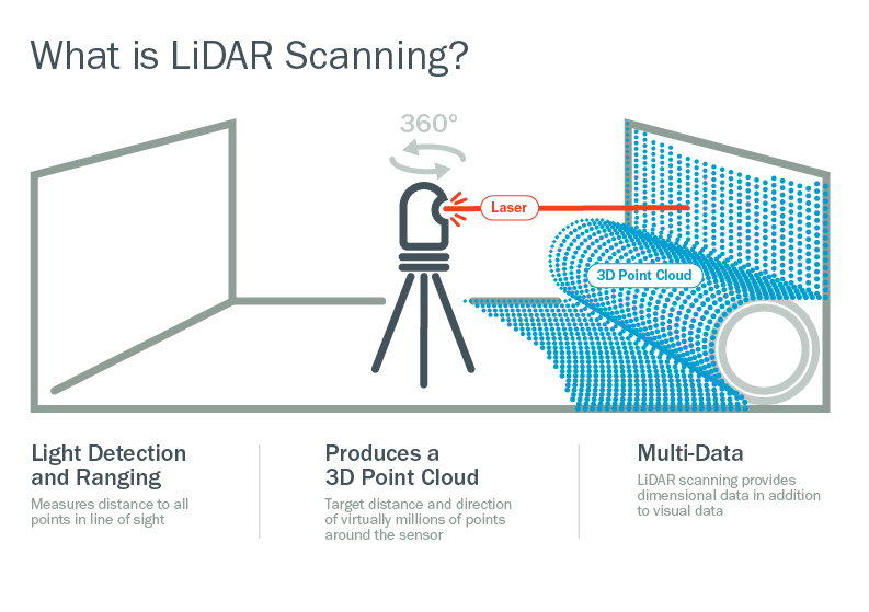
Laser Pulse 3D Scanning The way a laser scanner works boils down to beaming out light pulses at high speeds, which reflect off objects and return to the scanner's sensor (LiDAR). For each pulse, the distance between the scanner and the object is measured by calculating the elapsed time between sent and received pulses. Each data point is converted to a pixel with known x, y, and z coordinates.
A laser 3D scanner uses one of the three measurement technologies: time of flight, phase shift, or triangulation. Time-of-flight scanners calculate the time it takes for a laser pulse to reflect back to the scanner, while phase-shift devices measure distances by comparing modulated light wave patterns. Triangulation scanners, ideal for short-range measurements, use trigonometry to determine distances by forming a triangle between the laser source, the object, and the sensor, making them suitable for capturing small to medium-sized objects.
- Laser triangulation 3D scanning technology
-
Structured light 3D scanning technology
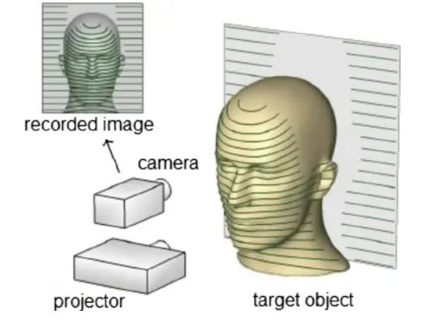
Structured Light 3D Scanning structured light is a precisely-calibrated pattern of white or blue light that a 3D scanner beams down onto whatever object you’re scanning. Usually this pattern is a series of parallel lines, stripes, or a grid. When structured light strikes the surface of the object, the pattern of light is distorted as it falls across any curves, depressions, or raised areas. As that's happening, the scanner's camera is capturing frame after frame of these distorted light patterns as they're reflected back, while the scanning software is analyzing the patterns and using them to accurately reconstruct in digital 3D all the surfaces of the object being scanned.
-
Photogrammetric technology
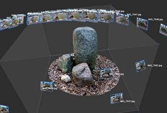
Photogrammetry Photogrammetry is a technology that delivers object 3D models by combining multiple photos of it. Unlike the professional 3D scanning technologies described above, photogrammetry requires no 3D scanner. 2D camera shots are processed by photogrammetry software, with many factors taken into account, primarily the camera's focal length, lens distortion & resolution, positions and angles of the camera when shooting the object, as well as having a sufficient field of view of the camera and overlap between the photos of adjacent areas.
- Computerized Tomography (CT scan)
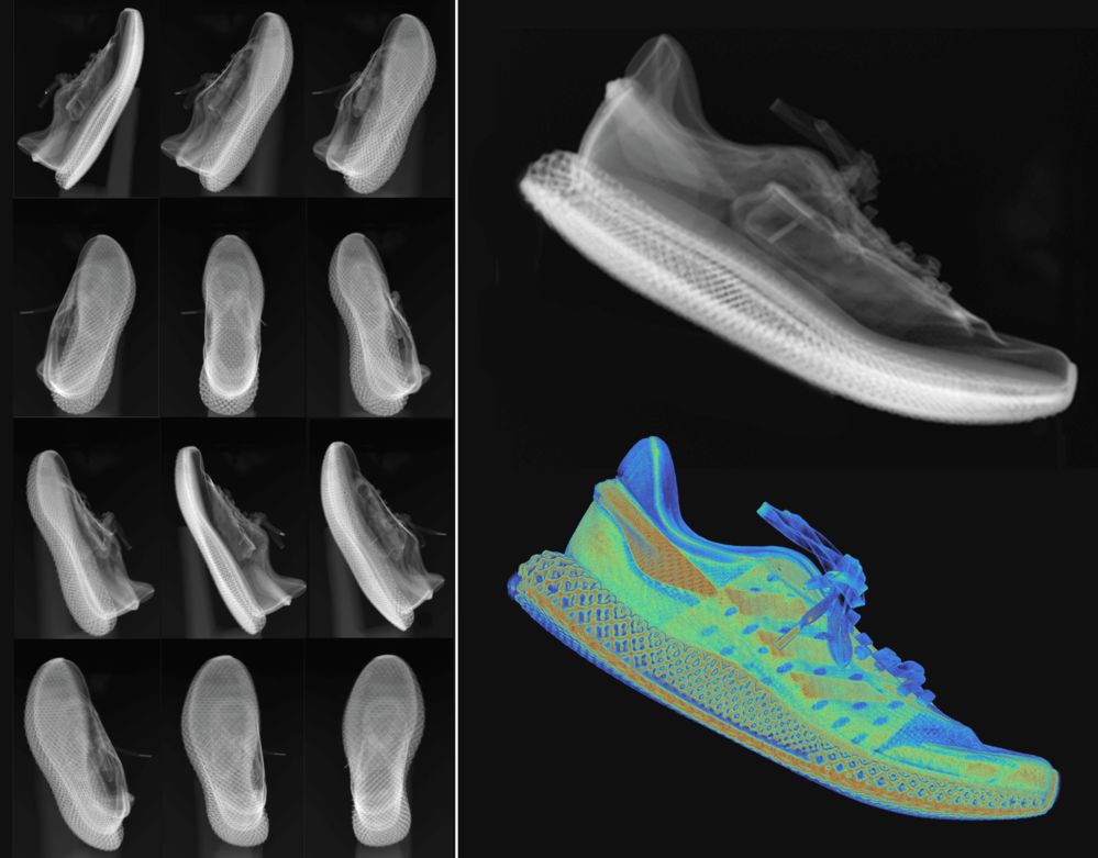
System Overview of RP2040 Industrial CT scanners take hundreds of X-ray images from different angles to capture the internal and external structure of objects in three dimensions. Medical CT scanners rotate an X-ray source and a detector around a human patient. Industrial CT scanners use a turntable to rotate an object between a stationary X-ray source and detector. As X-ray beams penetrate the object, they are attenuated at varying degrees depending on the density and composition of the material they traverse. The detector records these variances, generating what are known as X-ray projections or radiographs.
You can watch this video to know more about Industrial CT Scanning :What is Industrial CT
- Contact based Scanning
This process requires contact between the probe and the object, where the probe is moved firmly over the surface to acquire data.
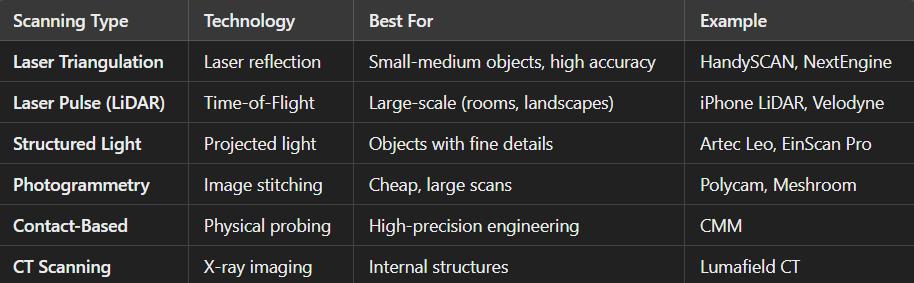
The below given Comparision table includes the common 3D scanning technologies used in the industry.
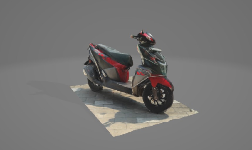
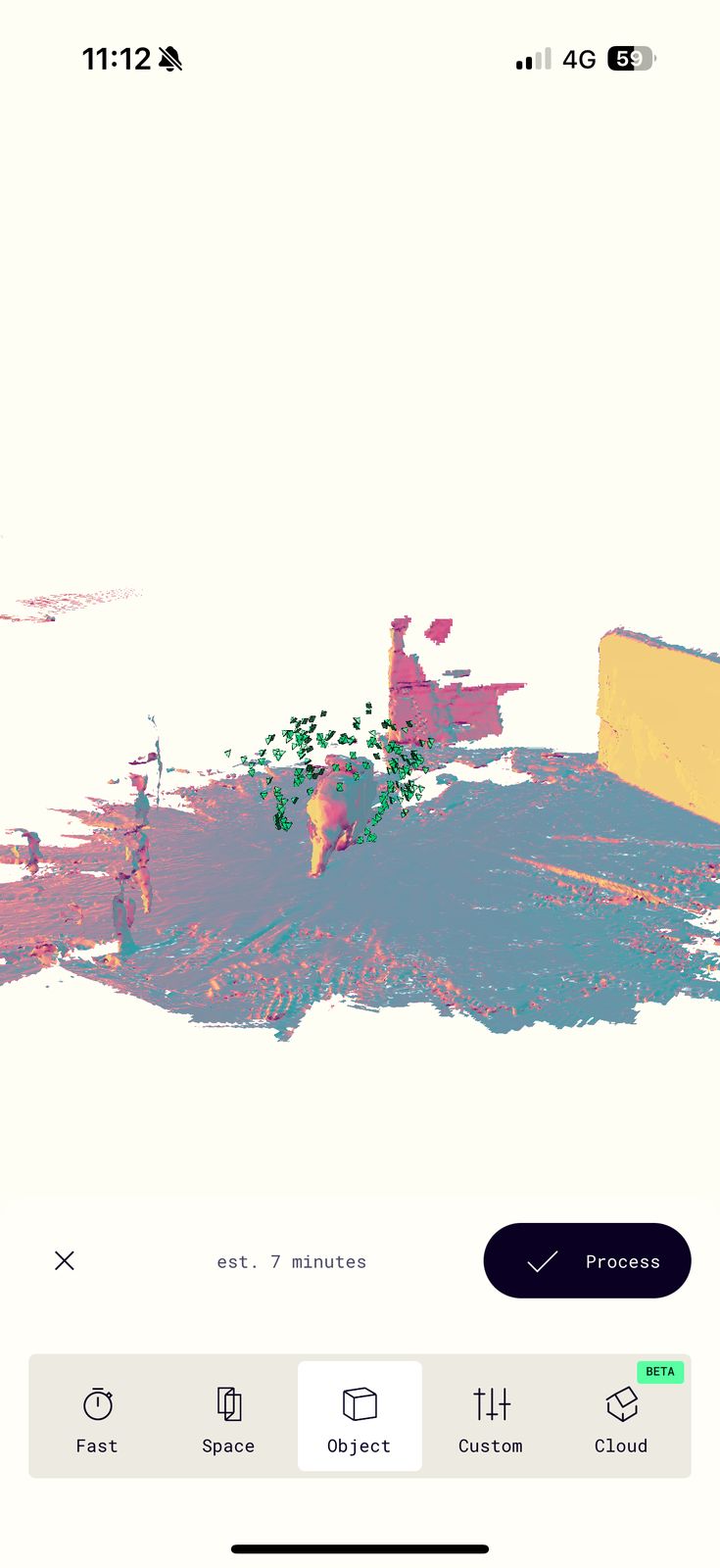
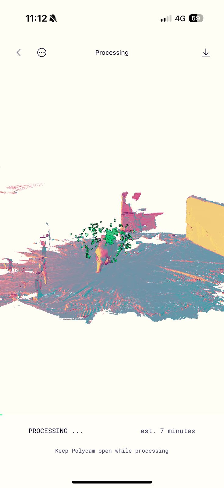
3D Scanning using Polycam
I used Polycam on Iphone 16
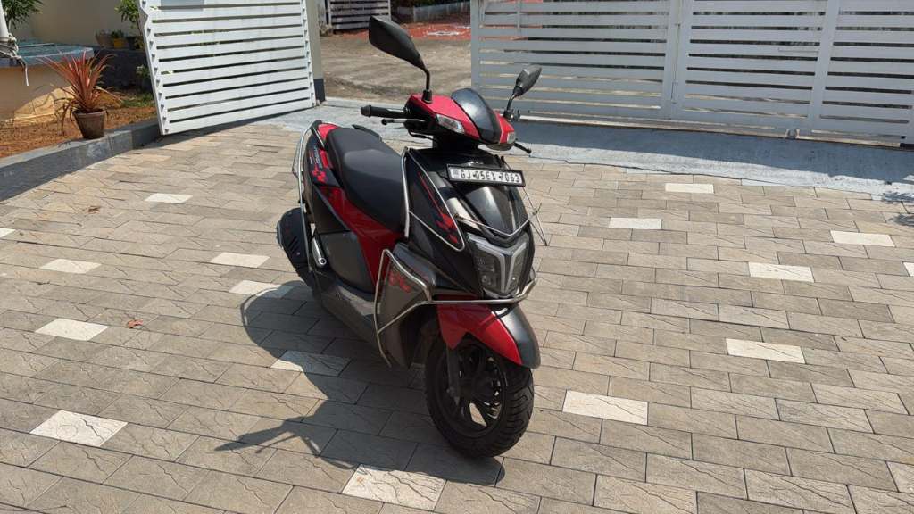
Polycam is a 3D scanning and modeling application that allows users to create high-quality 3D models using their smartphone or tablet. It is available on iOS and Android, with optimized performance on LiDAR-equipped Apple devices (iPhone 12 Pro and later, iPad Pro). Polycam supports multiple scanning technologies, making it versatile for different applications, from architecture and design to gaming and 3D printing.
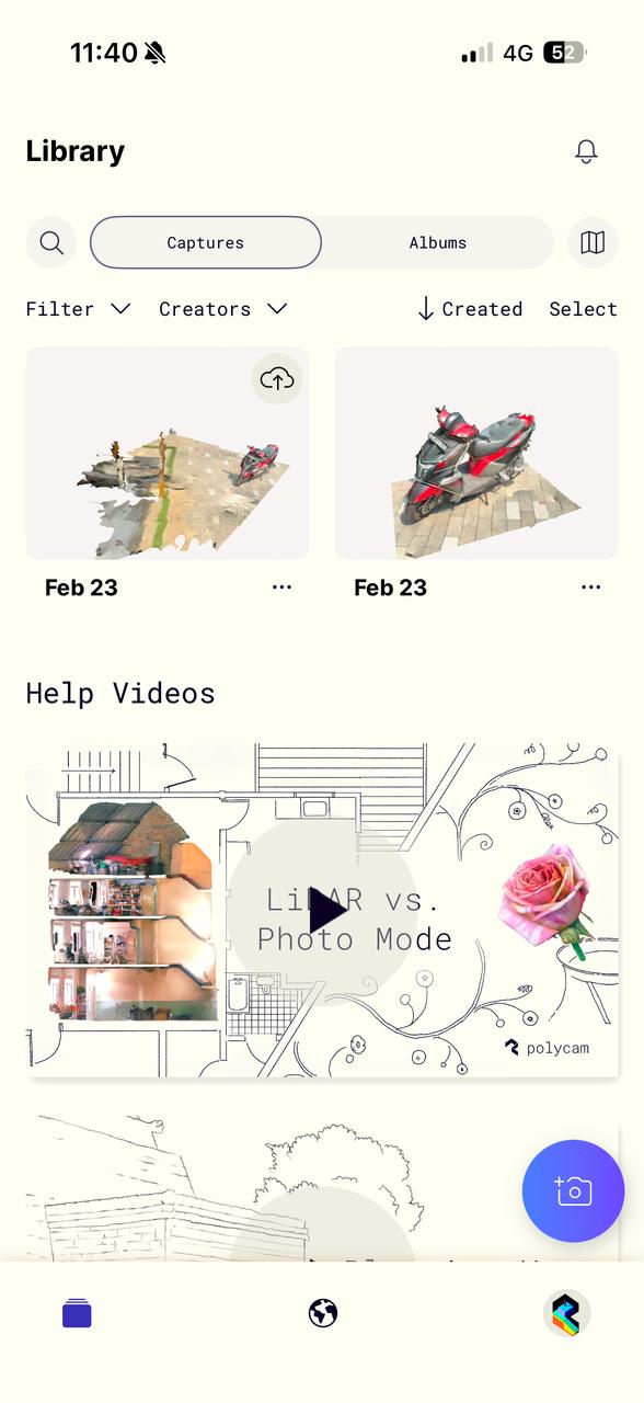
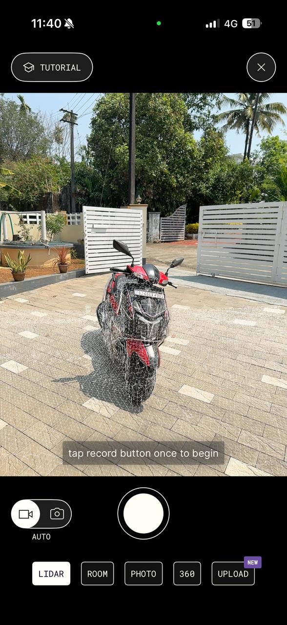
The technology that I used was LIDAR. Polycam leverages the LiDAR sensor in iPhone Pro and iPad Pro models to create highly accurate depth maps of scanned objects.
Design Files
You can download my design files from below
Design
3D Scan