This week, we explored Embedded Programming, learning to program microcontrollers and understand their architectures, toolchains, and workflows. We worked with different development environments, comparing compiled and interpreted languages. Key topics included memory management, peripheral interfacing, and debugging techniques. Through hands-on practice, we wrote, compiled, and flashed firmware, testing hardware interactions and communication protocols. This helped us understand how software controls embedded systems efficiently.
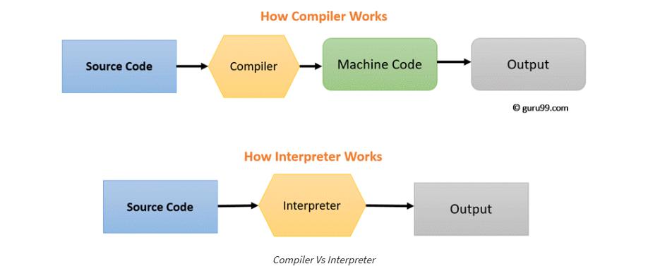
A compiler is a computer program that transforms code written in a high-level programming language into the machine code. It is a program which translates the human-readable code to a language a computer processor understands (binary 1 and 0 bits). The computer processes the machine code to perform the corresponding tasks.
What is an Interpreter
An interpreter is a computer program, which converts each high-level program statement into the machine code. This includes source code, pre-compiled code, and scripts.
Both compiler and interpreters do the same job which is converting higher level programming language to machine code. However, a compiler will convert the code into machine code (create an exe) before program run. Interpreters convert code into machine code when the program is run.
I refered to this site for knowing more about compilers and interpreters
I asked ChatGPT, what are compilers and interpreters in context of embedded programming. The prompt for the same was: compilers vs interpreters in context of embedded programming
For embedded programming
Compiler: A compiler translates the entire high-level source code into machine code (binary or assembly) before execution. The resulting binary file is flashed onto the microcontroller, allowing direct execution by the hardware.
Interpreter: An interpreter translates and executes code line-by-line at runtime, without requiring compilation into machine code beforehand.
Characteristics of Compilers:
✅ Fast Execution - Entire code is precompiled, leading to optimized performance.
✅ Efficient Resource Usage - No runtime interpreter, reducing memory and CPU overhead.
✅ Standalone Binary - Runs independently on the microcontroller after flashing.
❌ Slower Development Cycle - Requires recompilation and flashing after every change.
Characteristics of Interpreters:
✅ Rapid Development - No need to recompile; modify and run instantly.
❌ Slower Execution - Code is processed line-by-line instead of precompiled.
❌ Higher Memory Usage - Requires an interpreter to be stored in memory.
This week, we explored various embedded architectures, focusing on their development workflows and toolchains. We worked with the XIAO RP2040 using both Arduino IDE (C/C++) and Thonny (MicroPython), comparing compiled and interpreted approaches. The Arduino IDE allowed us to write and upload C++ code using the RP2040 core and GCC toolchain, while Thonny provided an interactive REPL environment for MicroPython, enabling quick testing without compilation.
Additionally, we experimented with the ATtiny1614, a lightweight microcontroller, using AVR toolchains and UPDI programming. We also explored an FPGA controller, understanding its hardware description language (HDL) workflow, synthesis, and bitstream uploading. Unlike microcontrollers, FPGAs provide hardware-level reconfigurability, requiring a different design approach.
Finally, we tested the Raspberry Pi 5, a powerful SBC running Linux, which supports high-level languages like Python and C++. We explored GPIO control, I2C, and SPI communication, demonstrating its flexibility for embedded applications. This hands-on experience gave us a deeper understanding of the strengths and limitations of each architecture, helping us choose the right tools for different applications.
Comparing different microcontrollers and toolchains
A microcontroller (MCU) is a small computer on a single integrated circuit that is designed to control specific tasks within electronic systems. It combines the functions of a central processing unit (CPU), memory, and input/output interfaces, all on a single chip.
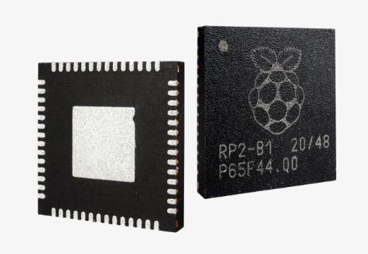
The microcontroller that I chose to explore this week was the Raspberry Pi RP2040
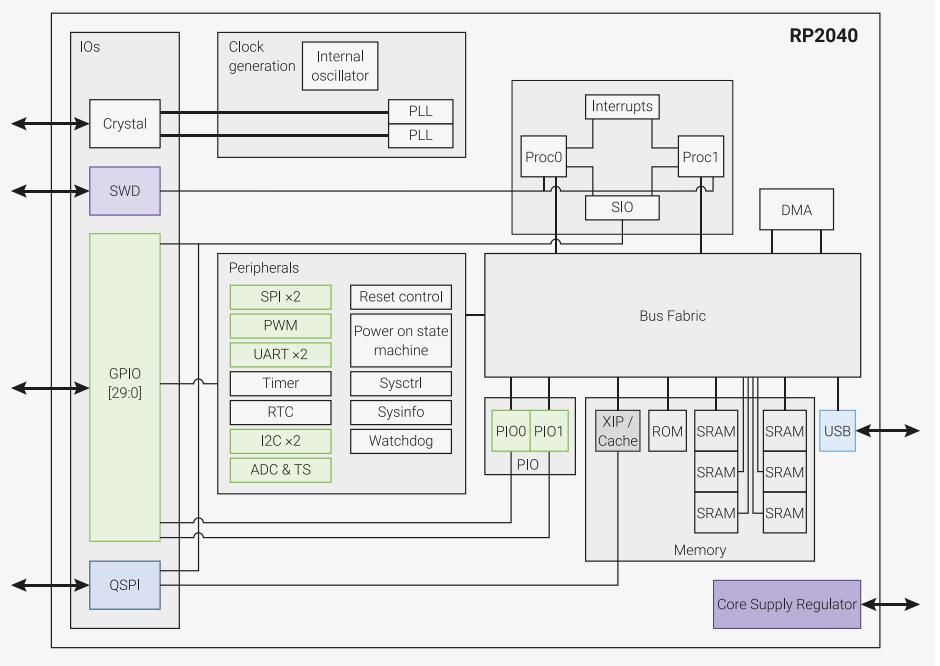
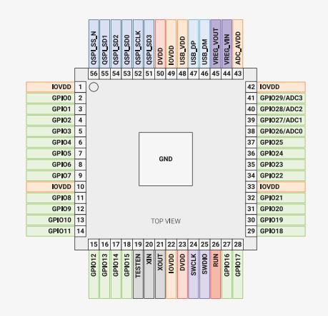
The RP2040 is a powerful, low-cost microcontroller from Raspberry Pi, featuring a dual-core ARM Cortex-M0+ processor running at up to 133MHz. It includes 264KB SRAM, supports up to 16MB external QSPI flash, and has 30 GPIO pins, with 2 UARTs, 2 SPI, 2 I2C, 16 PWM channels, and USB 1.1. A unique Programmable I/O (PIO) subsystem allows custom peripherals. Its DMA controller, AHB-Lite bus fabric, and low-power modes enhance performance and efficiency. With UF2 bootloader and MicroPython support, it's beginner-friendly while offering advanced capabilities for professionals in IoT, robotics, and embedded systems.
The above image shows the system overview of the RP2040 Microcontroller. I will explain the key features that I found important while choosing RP2040 as a microcontroller:
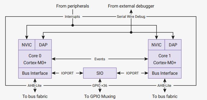
Dual Cortex M0+ processor cores:
The processor unit has two ARM Cortex M0+ cores which can run upto 133MHz, with a SIO(Single-Cycle Input Output), system interrupts and an SWD. Two cores allow for parallel processing, making it powerful for multitasking applications. Cortex-M0+ is optimized for low-power consumption and efficiency.
The RP2040 has 26 system-level interrupts, which can be routed to both processors.
The Serial Wire Debugger(SWD) interface is a debugging bus used to connect an external debugger to both processors.
The RP2040 does not have built-in Flash memory for storing programs. Instead, it executes code directly from external QSPI (Quad SPI) Flash memory. This approach provides customizable storage, allowing developers to choose the appropriate Flash size for their application.
For volatile (temporary) data, the RP2040 has 264KB SRAM, which is divided into six independent banks. This banked memory architecture prevents bottlenecks by allowing simultaneous access from different system components, improving overall performance.
GPIO and Peripherals
30 GPIO Pins (4 Analog Inputs)
The RP2040 has 30 multifunctional GPIO pins, which can be used as digital inputs or outputs. Each GPIO pin can be configured for SPI, I2C, UART, PWM, PIO, or digital I/O. 4 GPIOs (Pins 26, 27, 28, and 29) can be used as analog inputs. The GPIOs operate at 3.3V, and they are not 5V tolerant
12-Bit Analog to Digital Converter (ADC)
The RP2040 features a 12-bit ADC that allows it to convert analog signals (voltages) into digital values. The ADC outputs values from 0 to 4095 (2¹² = 4096 levels).
This means it can divide the input voltage into 4096 discrete steps for precise readings.
This is useful for reading sensors, measuring voltages, or interfacing with analog devices.
The four Analog Input GPIO Pins are:
GPIO26 (ADC0)
GPIO27 (ADC1)
GPIO28 (ADC2)
GPIO29 (ADC3)
There is also a inbuilt temprature sensor at ADC4. It measures the chip's temperature by sensing the voltage of an internal diode.
Multiple Communication Interfaces:
2x UARTs → For serial communication (e.g., talking to a PC or another microcontroller).
2x SPI Controllers → Fast data exchange with sensors, displays, and storage devices.
2x I2C Controllers → Used for connecting multiple sensors with just two wires.
16 PWM Channels:
Useful for generating analog-like signals (e.g., dimming LEDs, motor speed control).
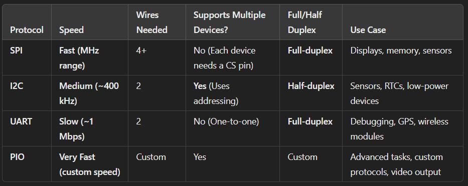
SPI (Serial Peripheral Interface) is a high-speed, full-duplex communication protocol commonly used to connect microcontrollers with sensors, displays, memory chips, and other peripherals. It has 4 wires : SCLK, MISO, MOSI, CS. One to Many Communication. Requires more wires (one CS line per child device).
I2C
I2C (Inter-Integrated Circuit) is a two-wire, half-duplex communication protocol, ideal for connecting multiple low-speed peripherals to a microcontroller.
Two wires: SCL(Clock) and SDA(Data). One to Many Communication. It uses an addressing system - Each device has a unique 7-bit or 10-bit address, so multiple devices can share the same bus.
UART
UART (Universal Asynchronous Receiver/Transmitter) is a serial communication protocol used for direct communication between two devices, such as a microcontroller and a computer. It is Asynchronous, thus doesn't require a clock. Both the parties commmunicate on the same baud rate. One to One Communication.
Voltage and Current Parameters
Core Voltage (Vcore): 1.1V (generated internally by the onboard LDO regulator).
GPIO Voltage: 3.3V - supplied externally, powers GPIOs and peripherals
GPIO Logic Levels (3.3V Logic)
Low (0): 0V - 0.8V
High (1): 2.0V - 3.3V
GPIO Current Limits
Max Source Current (per pin): 4mA
Max Sink Current (per pin): 4mA
Total Max Current (all GPIOs combined): 50mA
Power Supply Requirements
USB Power (VUSB): 5V (used when powering via USB).
3V3 Out (3.3V Output): Supplies up to 300mA for external components.
Power Consumption:
Active Mode (Dual Core Running @ 133MHz): ~15mA - 20mA
Deep Sleep Mode: ~1mA
Standby Mode: ~100µA
Comparision table of different interfacesUSB 1.1 with Host & Device Support:
Can act as a USB device (like a keyboard/mouse) or a USB host (reading data from peripherals).
Programmable Input Output
PIO (Programmable Input/Output) is a special feature of the RP2040 that allows the microcontroller to handle custom I/O protocols and high-speed data operations without using the CPU.
Write a program for a microcontroller, and simulate its operation, to interact and communicate
Embedded programming involves writing software that runs directly on microcontrollers to control hardware components. This requires handling input/output, managing communication protocols, and optimizing code for real-time execution.
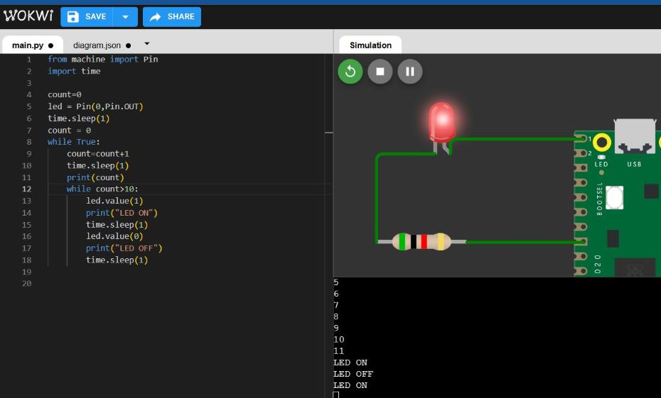
Pico on Wokwi
Raspberry Pi Pico using Wokwi Simulator
For this assignment, I programmed the Raspberry Pi Pico in MicroPython using the Wokwi simulator.
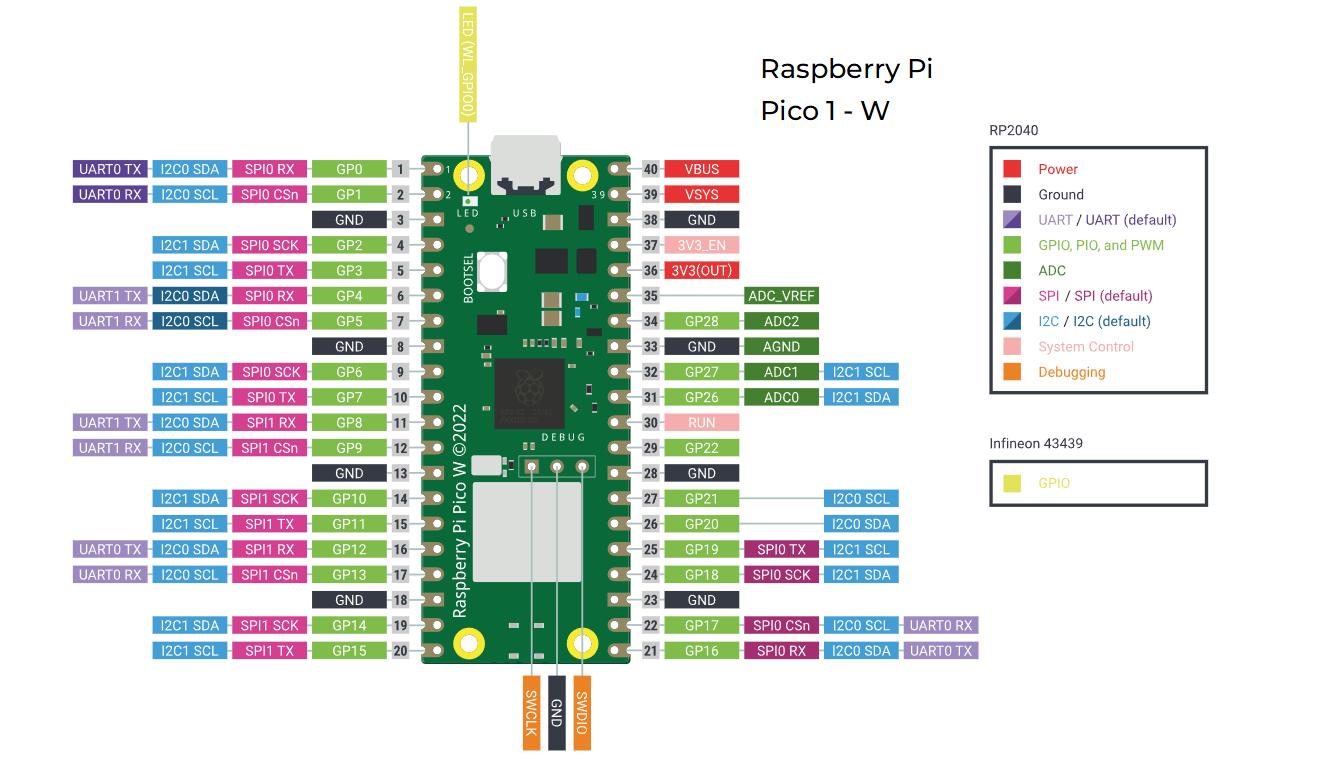
Raspberry Pi Pico
The Raspberry Pi Pico is a microcontroller board developed by Raspberry Pi, designed for embedded applications, automation, and hardware interfacing. Unlike Raspberry Pi single-board computers (which run Linux), the Pico is built for real-time control and runs bare-metal code or lightweight operating systems like MicroPython and C/C++. Key features include:
Microcontroller: RP2040 chip designed by Raspberry Pi
Processor: Dual-core Arm Cortex M0+, up to 133 MHz
Memory: 264KB SRAM, 2MB flash storage
USB: USB 1.1 with device and host support
Power Modes: Low-power sleep and dormant modes
Programming: Drag-and-drop mass storage via USB
GPIO: 26 multi-function pins
Interfaces: 2 x SPI, 2 x I2C, 2 x UART, 3 x 12-bit ADC, 16 x PWM channels
Additional Features: On-chip clock and timer, temperature sensor
Custom Peripherals: 8 x Programmable I/O (PIO) state machines
Module Types: Pico (castellated module), Pico H (pre-soldered headers)
Wokwi Simulator
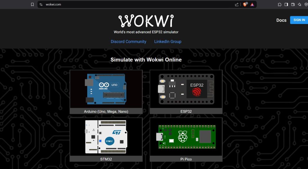
Wokwi is an online simulator for microcontrollers, allowing users to test and debug embedded systems without needing physical hardware. It supports various microcontrollers, including the Raspberry Pi Pico, Arduino boards, and ESP32, along with virtual peripherals like LEDs, buttons, sensors, and serial monitors.
To access Wokwi, visit wokwi.com and choose a microcontroller to simulate.
Wokwi Home PAge
The program reads a button press, toggles an LED, and transmits messages through a wired UART connection.
Micropython
MicroPython is a lean and efficient implementation of the Python 3 programming language that includes a small subset of the Python standard library and is optimised to run on microcontrollers and in constrained environments.
You can found it's documentation on micropython.org.
Micropython
Pico-Wokwi Workflow
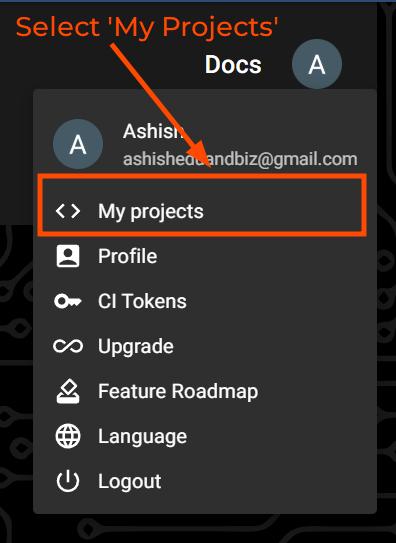
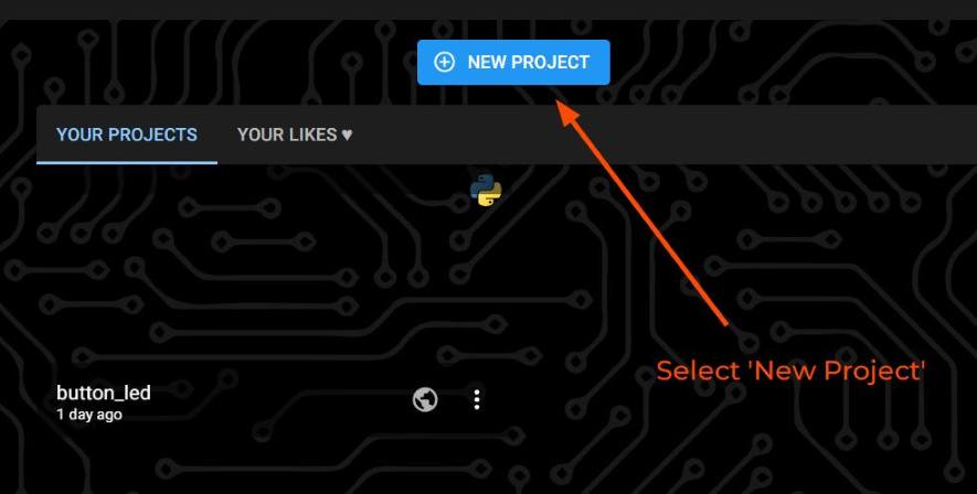
Setting Up the Environment
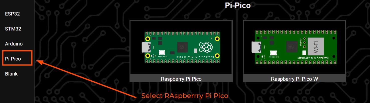
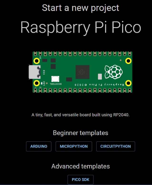
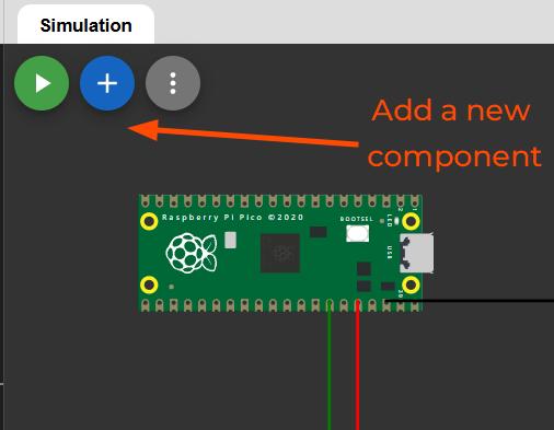
The first step in the process was setting up the Wokwi Environment. Open Wokwi and add a new project and select Pico as Microcontroller. And while selecting the language, select Micropython.
Selecting Raspberry PI Pico Selecting Micropython
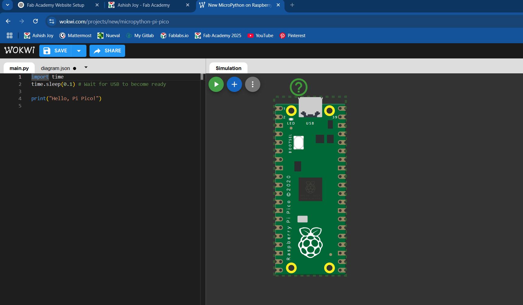
The Pico template will open as shown in the below figure. You can add components as you need and write code on the left window.
Pico Template
Designing the basic circuit
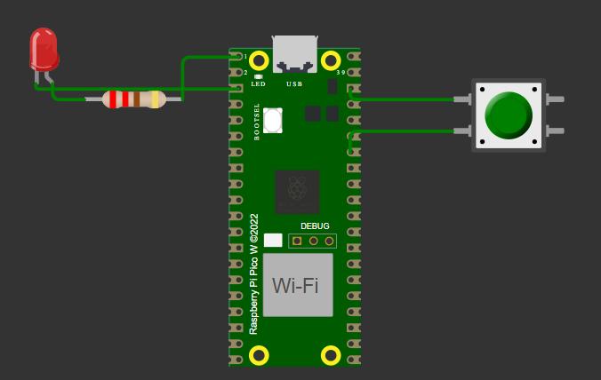
The first basic circuit that I wanted to test on the simualtion was to include a LED, a push button and the raspberrypi Pico.
The basic circuit consits of an an LED with resistor, Push button and the Raspberry pi Pico
Basic Circuit with IOWhy no pull up resistor?
You can see there is no resistor connected to the push button to pull it up HIGH. A pull up resistor is usually added to the push button so that button value is not floating. But here, the Raspberry Pi Pico W has an internal pull up resistor connected to the GPIO Pins, therefore I have not connected an external pull up resistor.
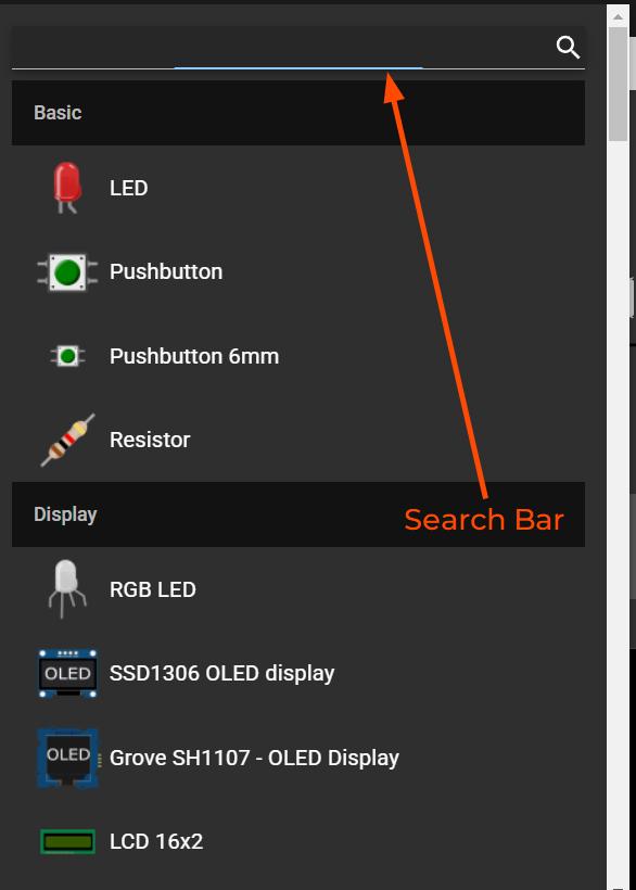
How to add components in WokwiAdding ComponentsSearch Bar for component search
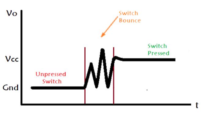
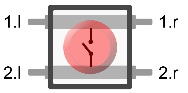
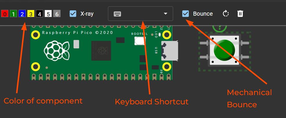
While adding components, you can change certain parameters such as color, add keyboard shortcuts and simulate real life parameters such as Mechanical bounce in push buttons (What is bouncing)
Adding Push Button: Different Parameters
Writing the Code
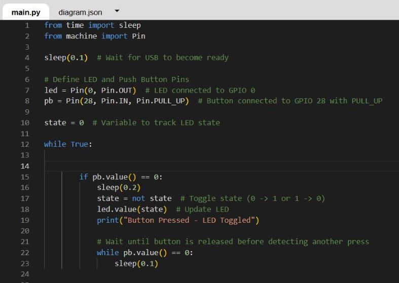
This is my first progam on Raspberry Pi Pico on Wokwi with Micropython.
The program is designed to read an input from a push button and control an LED based on button presses and also communicate via the Serial Monitor.
ChatGPT prompt: I want to write a simple MicroPython program for a Raspberry Pi Pico where an LED toggles on and off every time a push button is pressed.
from time import sleep
from machine import Pin

sleep(0.1)  # Wait for USB to become ready


led = Pin(0, Pin.OUT)
pb = Pin(28, Pin.IN, Pin.PULL_UP)

state = 0

while True:


        if pb.value() == 0:
            sleep(0.2)
            state = not state  # Toggle state (0 -> 1 or 1 -> 0)
            led.value(state)
            print("Button Pressed - LED Toggled")

            # Wait until button is released before detecting another press
            while pb.value() == 0:
                sleep(0.1)
ChatGPT prompt: Explain the code in detail
I'll explain the code in detail
Importing libraries
The top-most two lines are for importing required librarires for our program
from time import sleep
from machine import Pin
Th Pin function is imported from the machine library. The Pin function enables GPIO use for our Raspberry Pi-Pico and the sleep function helps to add a delay to the program.
Setting Up Pins
Before using the pins, they must be properly configured. The LED is connected to GPIO 0, which is set as an output pin, allowing the microcontroller to control its state (ON/OFF). The push button is connected to GPIO 28, which is configured as an input pin with an internal pull-up resistor. This ensures the pin remains in a stable HIGH (1) state when the button is not pressed, preventing it from floating—a condition where an unconnected input pin picks up random noise, leading to unpredictable behavior.
The state variable is initialized to 0. This variable will be used to track the LED
state = 0
Writing the Main Loop
The push button is pulled up by the internal pull-up resistor in the pin of the Pico. Therefore the push button is always HIGH unless it is pressed. The value of the pin is 0 when the push button is pressed. The sleep(0.2) adds a delay of 200ms to the program to avoid bouncing.
while True:
if pb.value() == 0:
	sleep(0.2)  # Debounce delay
	state = not state  # Toggle state (0 -> 1 or 1 -> 0)
	led.value(state)
	print("Button Pressed - LED Toggled")
Bouncing happens when a mechanical switch or button is pressed or released. Instead of an instant, clean transition from HIGH to LOW (or vice versa), the contact inside the switch vibrates for a few milliseconds, causing multiple rapid changes in state. This can lead to unintended multiple detections of a single press. Debouncing techniques, such as adding a small delay in code or using capacitors, help to eliminate this issue.
The delay of 200ms is added to the program to avoid bouncing.
The state variable toggles every time the push button is detected
led.value(state) controls the state of the LED
led.value(1) = LED is ON
led.value(0) = LED is OFF
Waiting for the release of button
The program waits for the button to be released before it continues to the next iteration of the loop. So while the push button is pressed pb.value() will read 0, and a delay will be there unless the button is not released.
while pb.value() == 0:
	sleep(0.1)
Simulating the Circuit
Simulate the program by clicking the play button and click on the push button. The Simulation helps to see the LED light up when the push buutton is pressed and the LED stays on until the push button is pressed again. The Serial Monitor
This basic program helped me understand how to program a microcontroller to interact with input/output devices and communicate via wired connections. Simulating it in Wokwi allowed for quick testing and debugging.
Interfacing ADC for Analog Pins
RP2040 allows for analog inputs using the ADCs.
ADC Interfacing
I tried to just connect the potentiometer and write a program like a digital pin expecting a 0 and 1 at the extreme ends of the potentiometer. I tried this approach because of my prior expereience in Arduino, wherein analogRead() and digitalRead() where used for analog and digital input, respectively. The digitalRead() value read atleast HIGH or LOW for analog pins in C, but I couldn't get any values for pot.value() in Micropython.
I refered to this documentation on potentiometers and Raspberry Pi Pico
from machine import ADC
from time import sleep

#initialising pin as ADC
pot=ADC(28) #ADC pins available are 26,27,28,29

pot_value=pot.read_u1
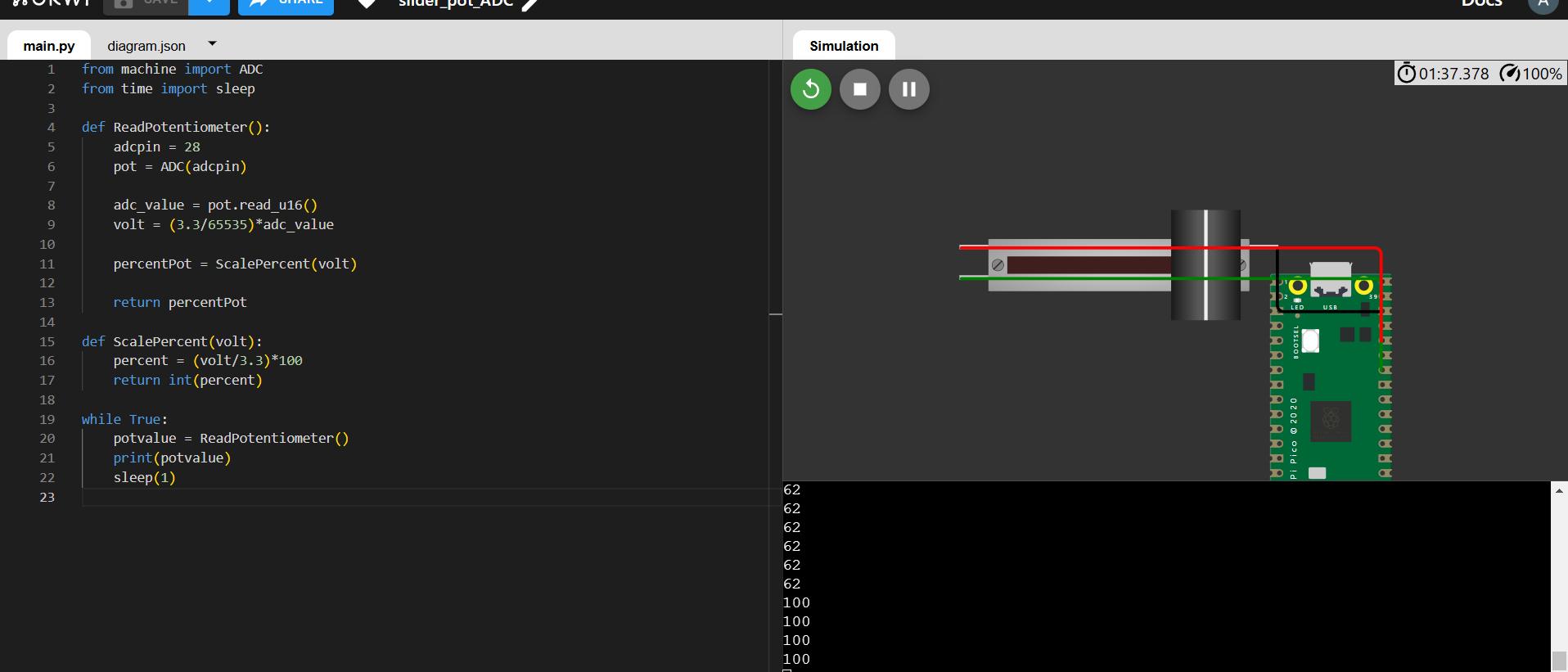
The below code adds some functions to map the ADC reading from the potentiometer to the GPIO Voltage i.e from 0 to 3.3 and the ScalePercent function maps that to a percentage value from 0 to 100.
from machine import ADC
from time import sleep
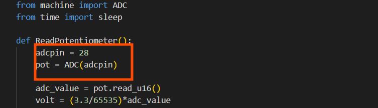
def ReadPotentiometer():
adcpin = 28
pot = ADC(adcpin)
adc_value = pot.read_u16()
volt = (3.3/65535)*adc_value #65535 is 2^16 because of the program reads 16bit
percentPot = ScalePercent(volt)
return percentPot
def ScalePercent(volt):
percent = (volt/3.3)*100
return int(percent)
while True:
potvalue = ReadPotentiometer()
print(potvalue)
sleep(1)
The RP2040's ADC has a 12-bit resolution, meaning it produces values ranging from 0 to 4095 (2¹² levels). However, MicroPython scales ADC readings to 16 bits for consistency across different microcontrollers. This means the .read_u16() function returns values from 0 to 65535 (2¹⁶ levels). Internally, the 12-bit reading is left-shifted by 4 bits (multiplied by 16) to fit the 16-bit range.
Interfacing PWM pins
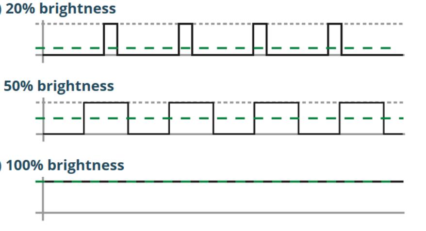
PWM, or Pulse Width Modulation, is a technique that controls the power delivered to devices. It achieves this by turning the power on and off very quickly. There is no Digital to Analog Converters on the PICO, therfore to simulate analog signals PWM is used.
PWM works by producing an output that changes between HIGH and LOW at a very high frequency. The duty cycle is responsible for the intensity of the signal. The duty cycle refers to the percentage of time the power is on compared to the total time of the on-off cycle—take a look at the following diagram.
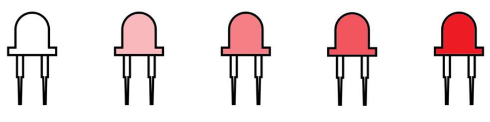
A duty cycle of 50 percent results in 50 percent LED brightness, a duty cycle of 0 means the LED is fully off, and a duty cycle of 100 means the LED is fully on. Changing the duty cycle is how you produce different levels of brightness.
The Raspberry Pi Pico has 8 independent PWM generators called slices. Each slice has two channels, which makes a total of 16 PWM channels.
Test on Board
Test the program on the board
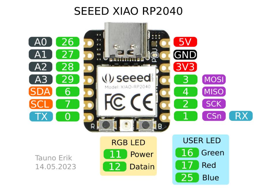
After succesfully simulating my program, I wanted to run the program on the board. As we have a XIAO RP2040 Board, I tried blinking an LED on XIAO RP2040 using two workflows: Arduino IDE (c++) and Thonny (Micropython)
We used the Arduino IDE to program the XIAO RP2040. The XIAO RP2040 is compatible with the Arduino IDE, allowing users to write and upload code using the familiar Arduino programming environment. This compatibility makes it easier for developers to transition from other Arduino boards to the XIAO RP2040.
Arduino IDE
The Arduino IDE is a popular open-source platform for programming microcontrollers. It provides a user-friendly interface, a vast library of pre-built functions, and a large community for support. The IDE allows users to write code in C/C++, upload it to the microcontroller, and monitor serial output.
To program the XIAO RP2040 using the Arduino IDE, you need to install the necessary board definitions and libraries. This process involves adding the Seeed Studio board manager URL to the Arduino IDE preferences and installing the XIAO RP2040 board package. Once set up, you can write code in C/C++ and upload it directly to the board via USB.
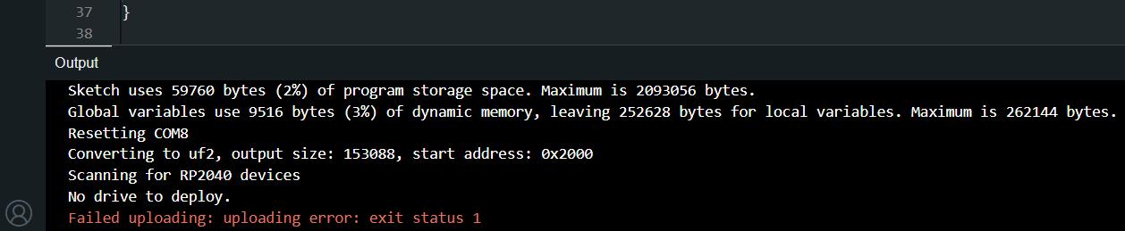
Using uploading the code we found an error with the bootloader, because we were switching our workflow. We tried different methods to figure out what was going wrong, but failed. The below message is the error what was shown every time we tried to upload the code.
Failed Upload in Arduino IDE
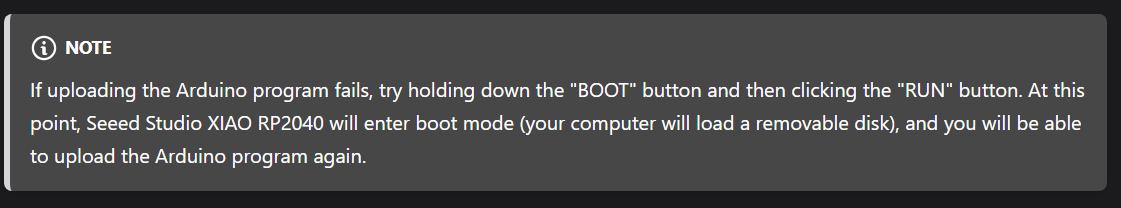
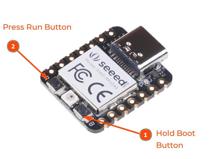
The documentation mentioned about this issue, and we tried to follow the steps but we couldn't figure out what the run button. Due to my presumption that the R on the board must be the reset button and not run. But later our instructor said to follow the below step: Hold the boot button and press Run
About the issue on documentationHold Boot + Press Run
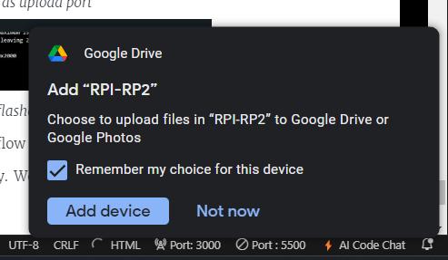
The above step makes the system into bootloader mode and the device(XIAO-RP2040) is detected as a Mass Storage Class device
MSC Detected
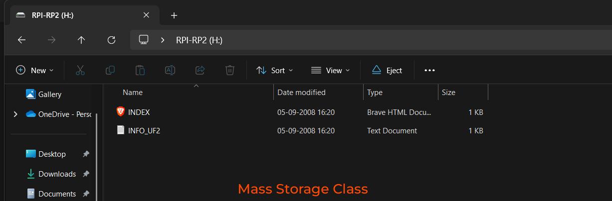
The Mass Storage Class (MSC) is a USB device class that allows embedded systems, like the Xiao RP2040, to appear as a flash drive when connected to a computer. This simplifies firmware updates, as users can drag-and-drop firmware files instead of using specialized flashing tools.
Mass Storage Class
In the Xiao RP2040, MSC is used for firmware programming via the UF2 bootloader. When the board is in bootloader mode, it mounts as a USB drive, making firmware installation as easy as copying a file.
UF2 Bootloader in Xiao RP2040:
UF2 (USB Flashing Format) is a special file format designed for easy firmware flashing. It was developed by Microsoft and is used in microcontrollers like the Xiao RP2040 to facilitate firmware updates via USB without needing external programmers.
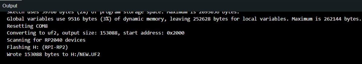
Succesfully flashed program
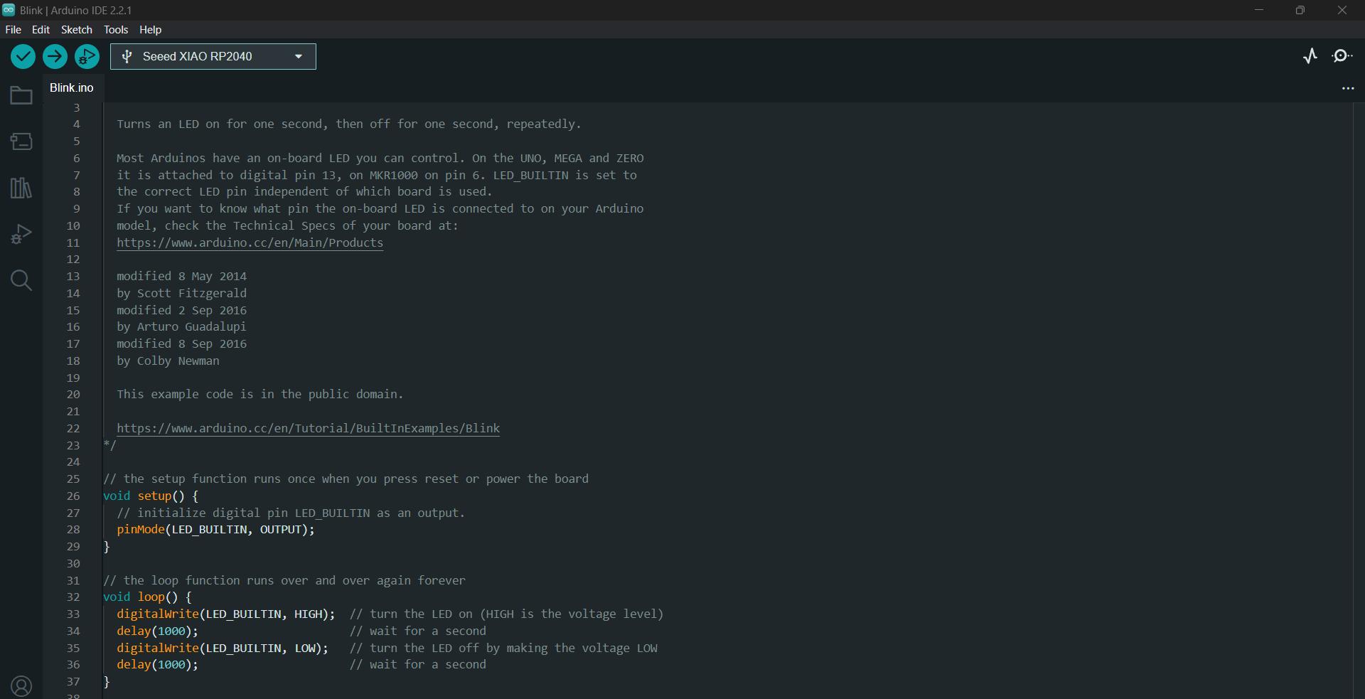
The XIAO RP2040 is programmed using the ARDUINO IDE using C
int blue = 25;
int red = 17;
int green = 16;

void setup() {
	pinMode(blue, OUTPUT);
	pinMode(green, OUTPUT);
	pinMode(red, OUTPUT);

	//The LEDs are Pulled UP HIGH

	digitalWrite(green, HIGH); // Turn OFF green LED
	digitalWrite(red, HIGH);   // Turn OFF red LED
}

void loop() {
	digitalWrite(blue, LOW);   // Turn ON blue LED
	delay(1000);               // Wait for a second
	digitalWrite(blue, HIGH);  // Turn OFF blue LED
	delay(1000);               // Wait for a second
}
The XIAO RP2040 has 4 LEDS:
1 RGB
1 Red
1 Green
1 Blue
The change from interpreter to compiler workflow for the same RP2040 showed an error because of we failed to load the bootloader incorrectly. We couldn't understand what went wrong. The documentation helped to make it right.