Computer Controlled Cutting
This week, we explored Computer-Controlled Cutting, learning how to operate laser cutters and vinyl cutters for precise digital fabrication. We focused on understanding laser cutter parameters such as power, speed, focus, and kerf to achieve accurate cuts and proper joint clearances. Additionally, we applied parametric design principles to create construction kits that can be assembled in multiple ways. Through hands-on practice, we refined our skills in preparing vector files, optimizing cutting settings, and adjusting designs based on material properties.
Learning Objectives
Assignments
Group Assignments
Individual Assignments
Group Assignment
As part of the group assignment, we conducted lab safety training and characterized the laser cutter's settings, including focus, power, speed, rate, kerf, joint clearance, and types of joints.
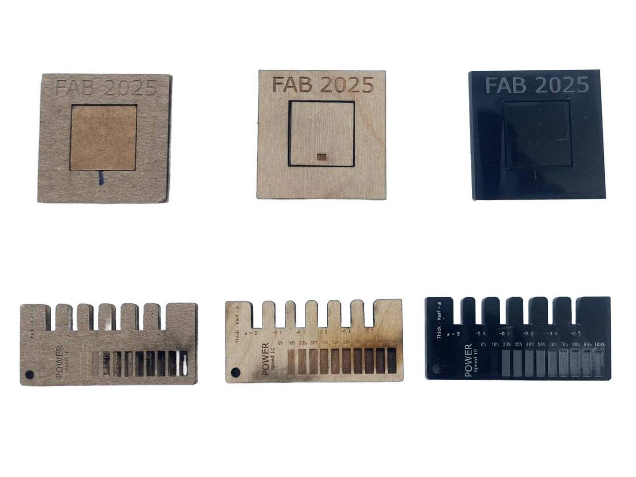
Through this group assignment, I gained a deeper understanding of laser cutter characterization by testing various parameters such as focus, power, speed, kerf, joint clearance, and engraving settings. This process helped me analyze how different materials behave under laser cutting and how to optimize settings for precision and efficiency.
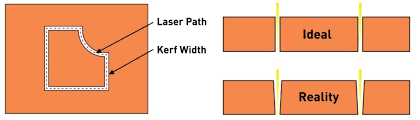
One of the key concepts I explored was kerf, which is the material removed by the laser beam during cutting. Since the laser burns away a small portion of the material, the actual cut piece ends up slightly smaller than the original design, and the hole left behind is slightly larger. Measuring and accounting for kerf is crucial when designing parts that need to fit together precisely, especially for press-fit assemblies.
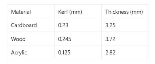
To determine the kerf for different materials, we performed test cuts on cardboard, acrylic, and birch wood. We designed and cut small rectangular pieces, then measured the difference between the designed and actual cut dimensions. By dividing the total difference by two, I calculated the kerf value for each material.
The group assignment can be found on this Group Assignment
Individual Assignments
Cutting on the Vinyl cutter
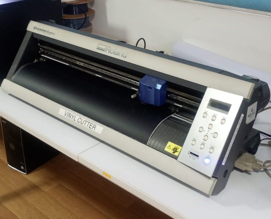
Roland GS-24 Vinyl Cutter
For cutting vinyl, I used the Roland GS-24 Vinyl Cutter, a precision machine designed for cutting thin materials like adhesive vinyl, heat transfer vinyl, and stencils. To send my design files to the machine, I used MIT's MODS software, a web-based tool that allows for custom processing and direct machine communication.
What is MODS?
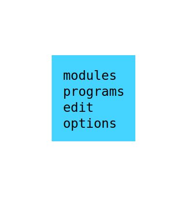
MODS is an open-source, browser-based tool developed by MIT for converting design files (SVG, PNG, DXF, etc.) into machine-readable formats. It provides a modular approach to customizing toolpaths, setting cutting parameters, and sending commands directly to fabrication machines like vinyl cutters, laser cutters, and CNC mills.
Vinyl Cutting Workflow
Design the vinyl sticker
The first step in the process was preparing my design. I created a vector design in Inkscape, ensuring the design was a single-color outline suitable for cutting. The design file was then saved in SVG format for compatibility with MODS.

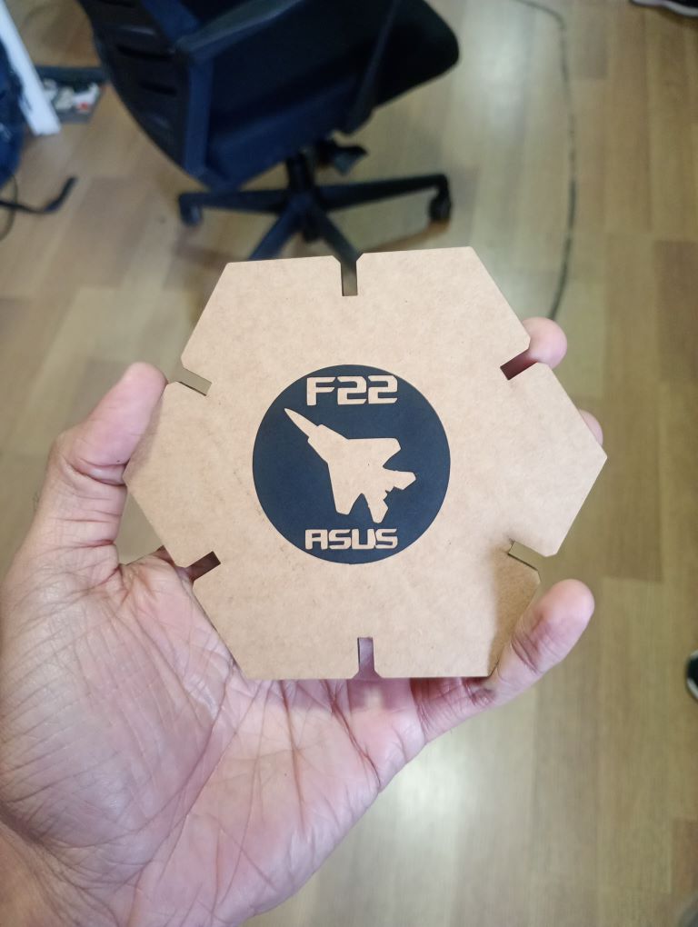
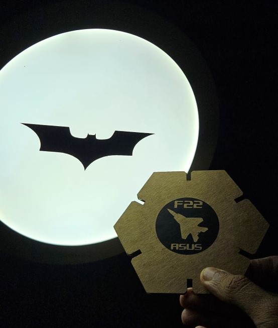
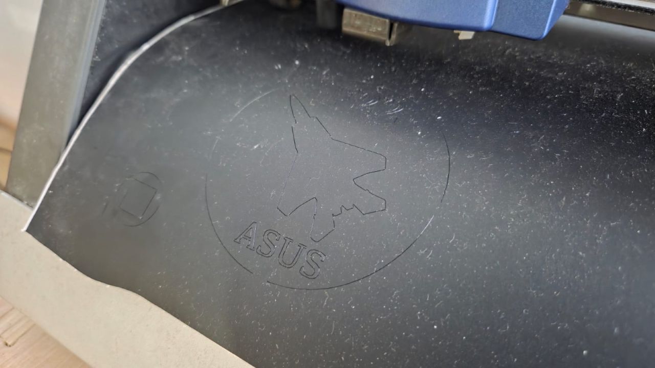
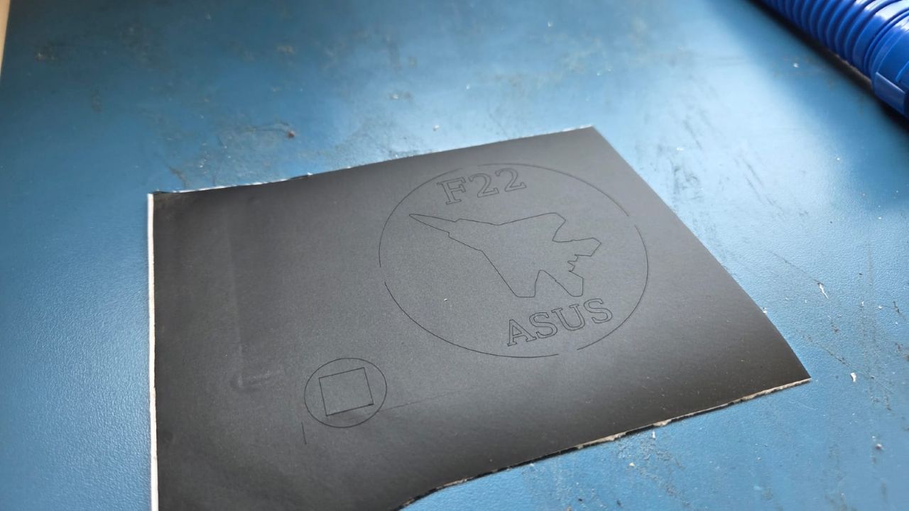
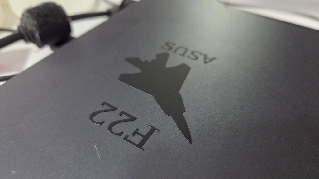
Designing in Inkscape I decided to try some images of planes which I got from Flight Image and batman logo
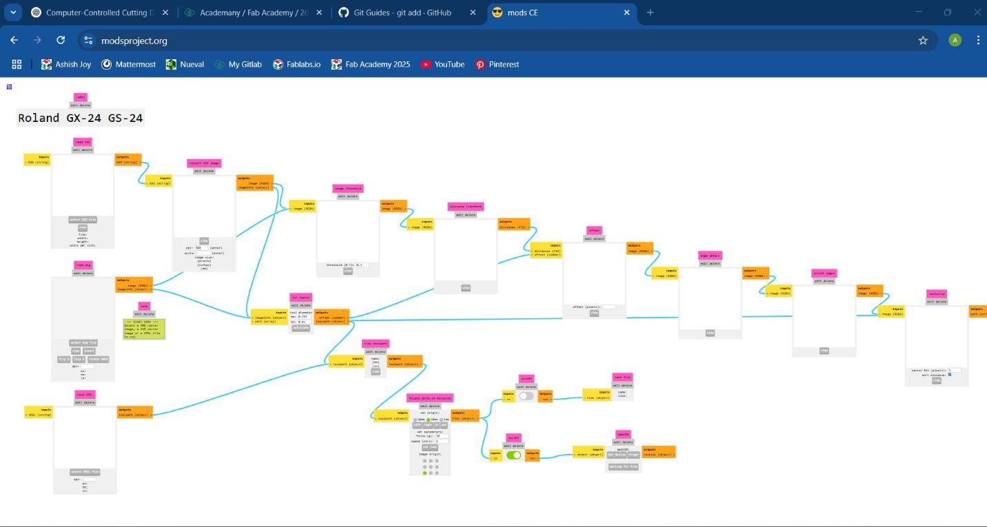
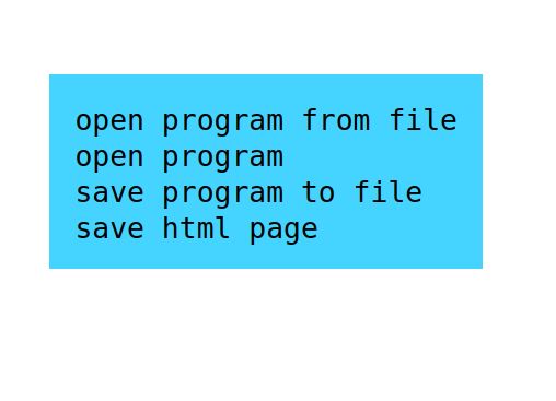
Open MODS and Load the File
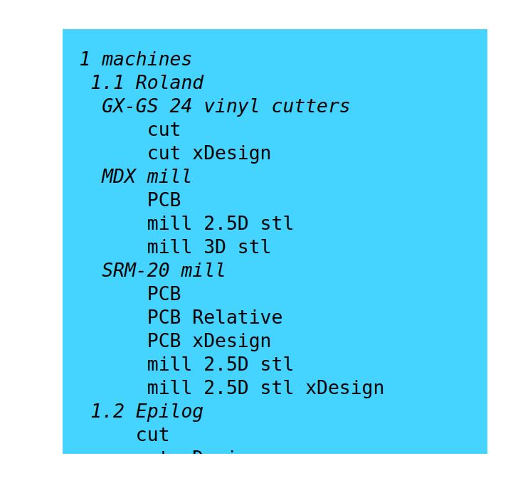
Navigate to mods.cba.mit.edu and select the Roland GS-24 workflow
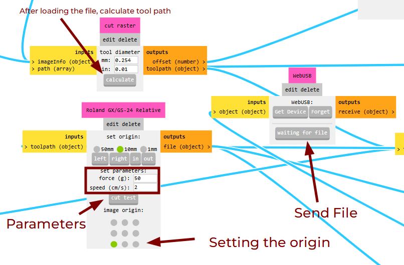
Set Cutting Parameters
For precise cutting, I adjusted the speed, typically around 1 cm/s, and set the force according to the material thickness, which was 100gf for regular vinyl. The working quadrant was also defined to align the design within the cutter's workspace.
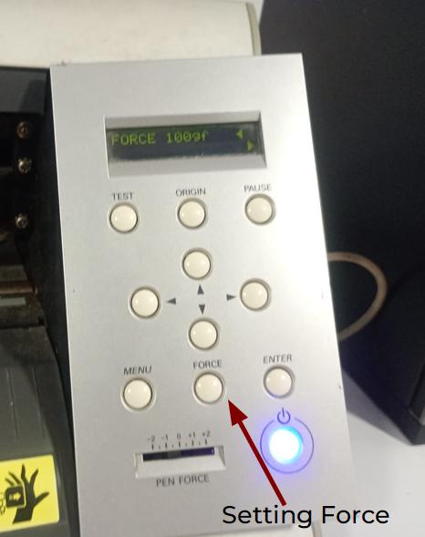
Setting Force Cutting Speed: 1 cm/s
Cutting Force: 100gfLoad the Vinyl in the Cutter
Once the settings were configured, I loaded the vinyl into the Roland GS-24. I carefully aligned the vinyl sheet with the rollers to ensure it fed correctly through the machine. Using the "ORIGIN" button on the cutter, I set the starting point for the job.
Send the Job to the Cutter
After confirming everything was properly set up, I clicked "Calculate" in MODS to generate the toolpath and then "Send" to transfer the file to the Roland GS-24. The cutter precisely followed the design path, cutting out the shapes.
Setting up and Sending the job Weeding and Application
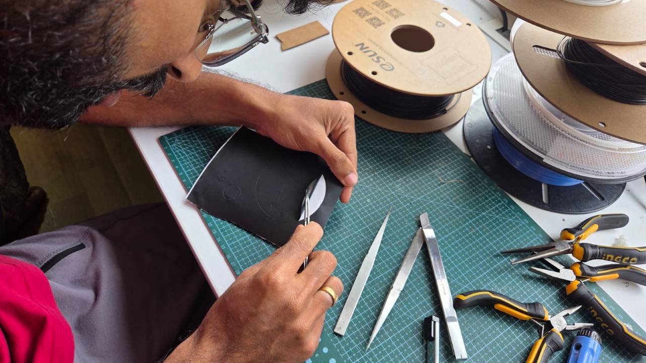
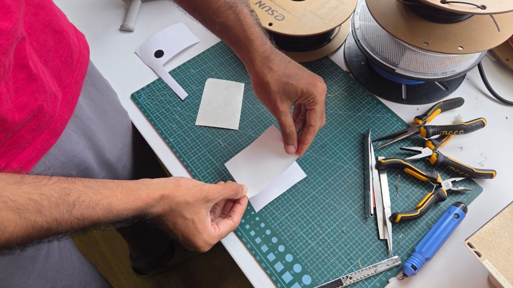
After cutting, I carefully removed the excess vinyl using a tweezer tool, leaving only the desired design. To apply the cut vinyl to a surface, I used transfer tape to lift and place it smoothly onto the final material.
Carefully removing the excess and unnecessary vinyl parts of the stickers using tweezers to get only the necessary sticker portion.
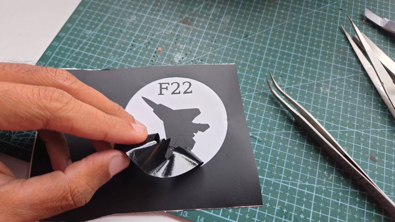
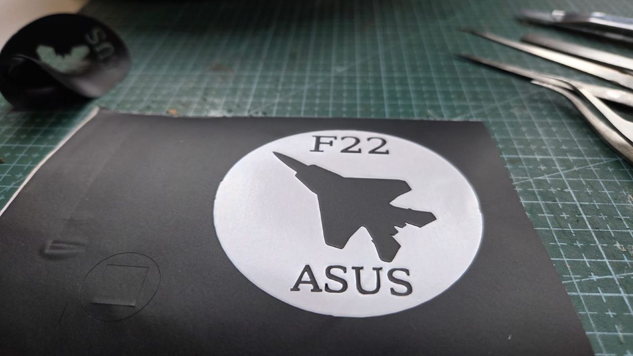
The unnecessary portion is completely removed using tweezers leaving behind the sticker.
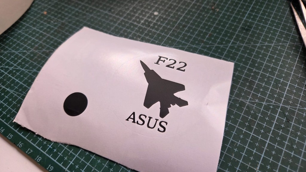
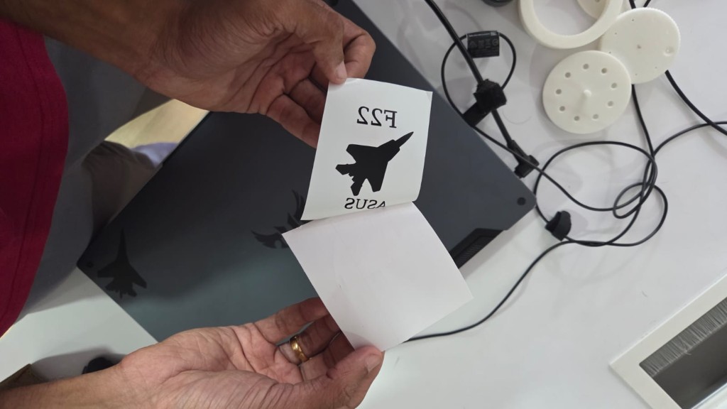
After removing the excess vinyl, I applied transfer tape over the design to lift it off the backing paper. This tape helps in transferring the vinyl to the desired surface without losing its shape or alignment.
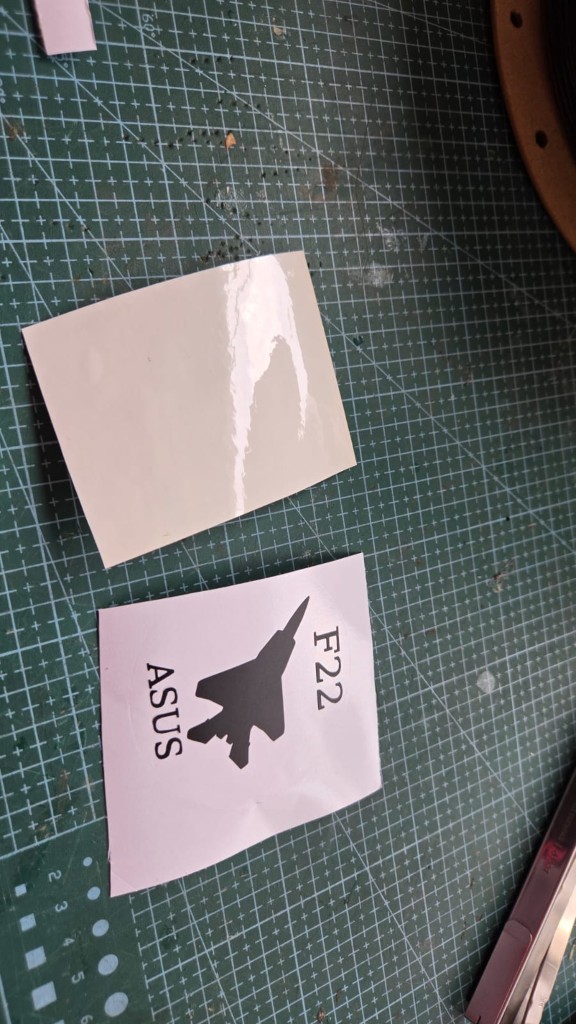
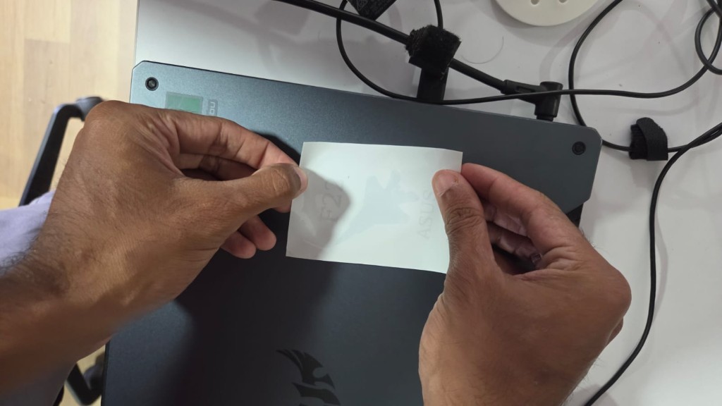
After applying the transfer tape, I removed the backing paper of the vinyl sticker.
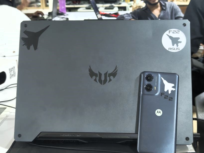
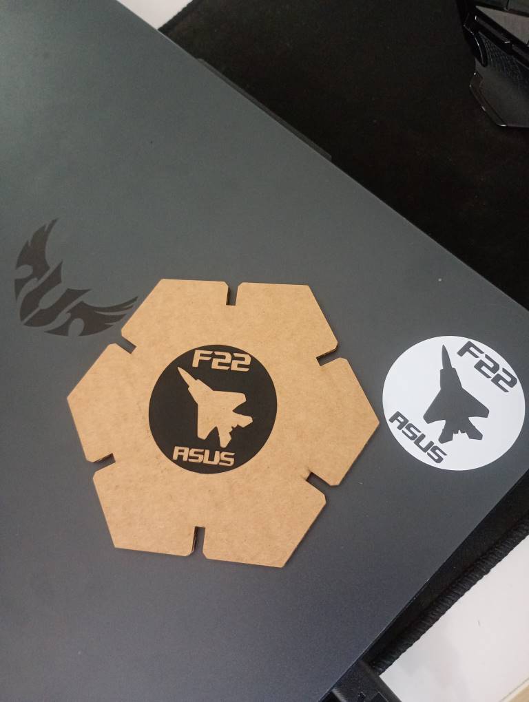
Once the transfer tape was applied, I carefully positioned the sticker on the target surface. Using a squeegee, I pressed down firmly to ensure good adhesion and remove any air bubbles. After that, I slowly peeled off the transfer tape, leaving the vinyl sticker in place.
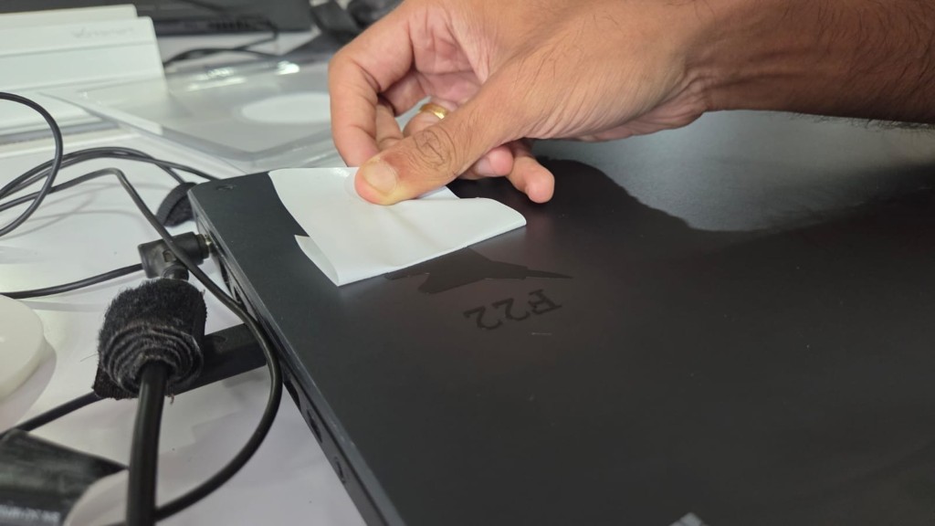
After ensuring the sticker was securely applied, I carefully removed the transfer tape, revealing the final design. The result was a clean and professional-looking vinyl sticker ready for use.
Parametric Construction Kit
Demonstrate and describe parametric 2D modelling processes.
In this project, I used Fusion 360 to create a parametric 2D design for a laser-cut construction kit. Parametric modeling allows for easy adjustments by defining relationships and constraints between elements, making it ideal for designing parts that need precise fits, such as press-fit joints.
Setting Up Parameters
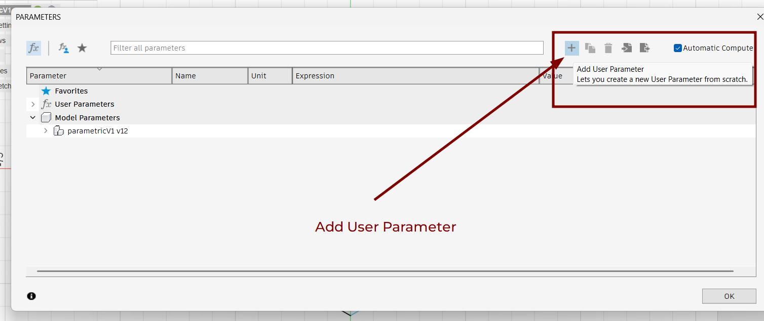
To ensure flexibility in my design, I used the Change Parameters tool found in the Modify space in Fusion 360.
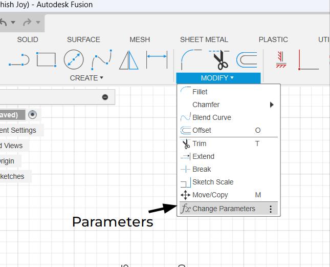
In this window, I could define key parameters that would control the dimensions of my design. This approach allowed me to easily adjust the size of the parts without manually changing each dimension in the sketches.
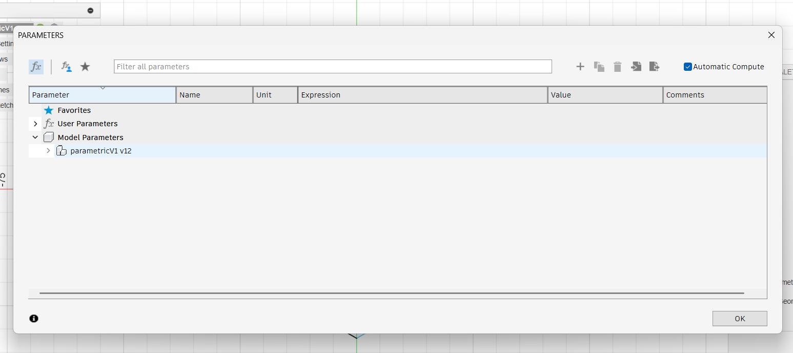
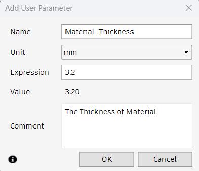
Here, I have created a parameter called Material_Thickness and expression 3.2
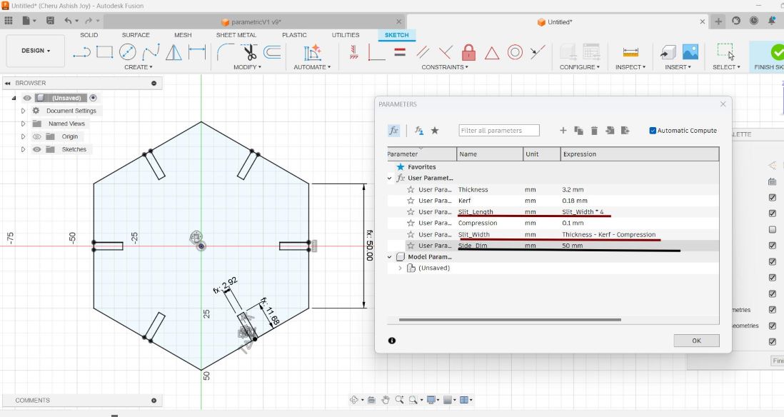
I created and assigned key parameters to control dimensions dynamically:
- Thickness - Defines the thickness of the material used for cutting.
- Kerf - The width of material removed by the laser, which needs to be accounted for in joints.
- Compression - The amount of material to be compressed when assembling the kit.
- Slit width - The width of the slits for press-fit connections, calculated as Material_Thickness - Kerf - Compression to ensure a snug fit.
- Slit_Length - The Length of the Slit calculated as slit_width * 4
- Side_Dim - The Dimension of the Side of the shape
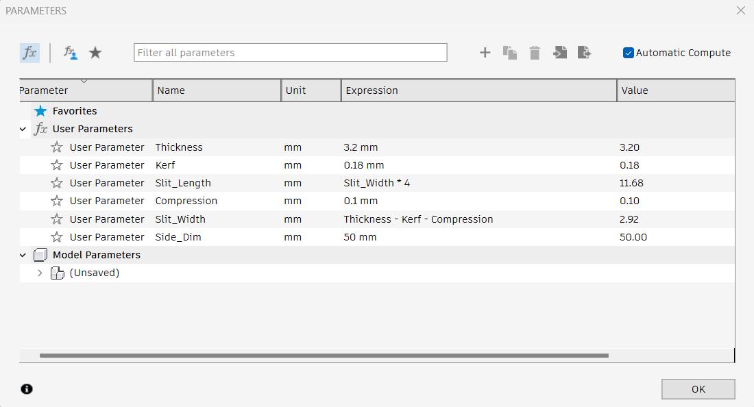
By defining these parameters, I could easily modify my design for different materials or fine-tune the fit without manually editing each sketch.
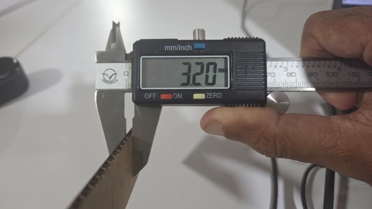
I found the thickness of the cardboard to be 3.2mm, measuring it using a vernier calliper
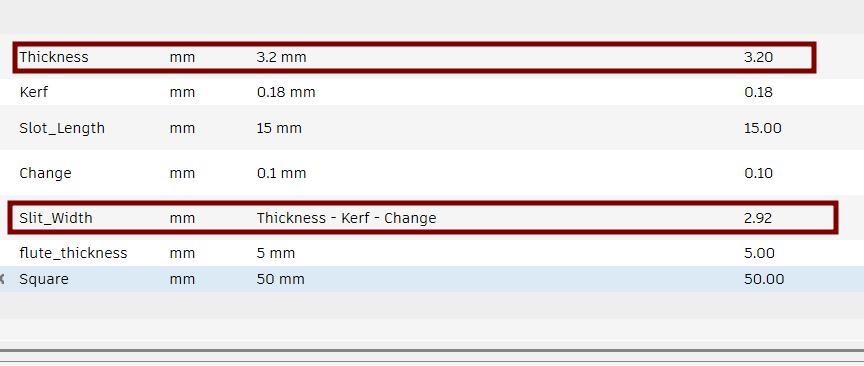
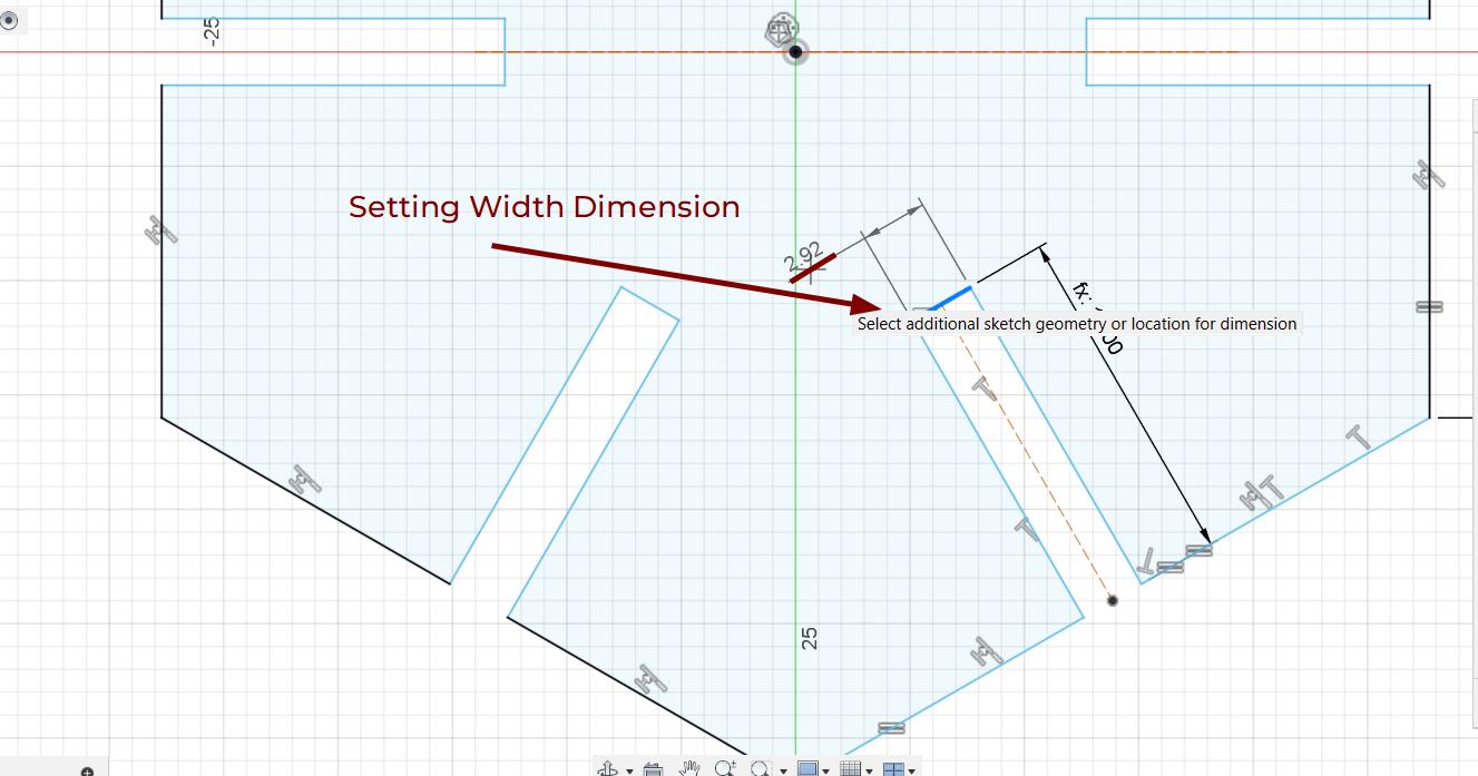
With the parameters set, I could now create sketches that utilized these dimensions. For example, the slit width was defined as Material_Thickness - Kerf - Change(Compression), ensuring that any changes to these parameters would automatically update the slot dimensions in my design.
Here, I am adding dimension to the width of the slit.
I can enter the Slit_Width parameter to the dimension.
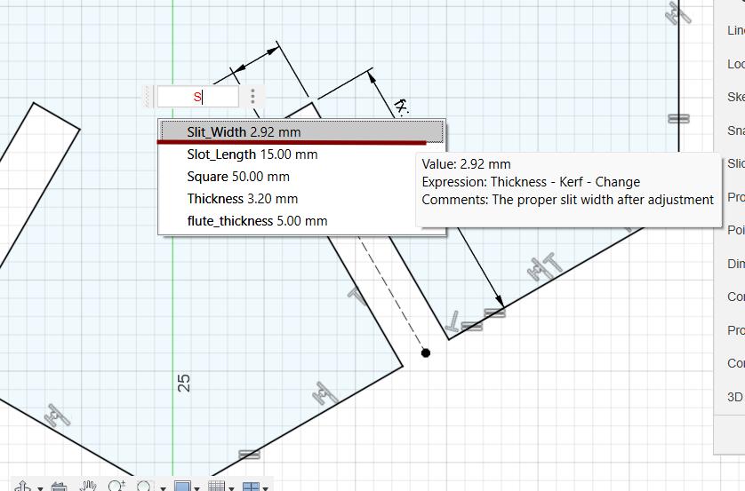
You can see the fx: 2:92 text, the fx tag is for parameters.
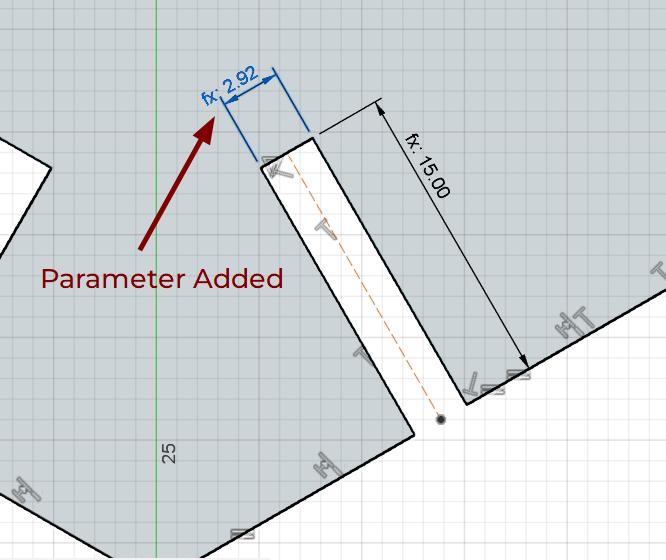
The parameter is added successfully. The other parameters are also added similarly.
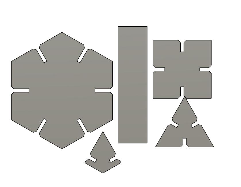
Designing Parametric Shapes
I designed several modular shapes that could be assembled in multiple ways:
- Hexagon - A versatile base shape with slots for interlocking connections.
- Triangle - Another structural element that adds variety to the construction.
- Joint Connector - A specialized piece designed to join different parts together at various angles.
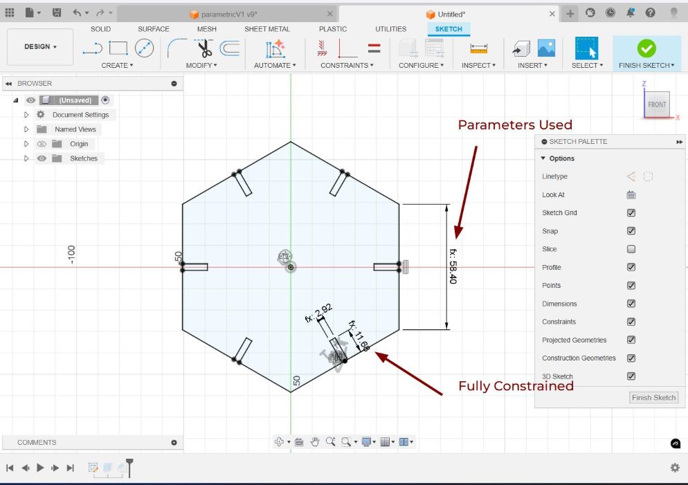
Each shape was fully constrained with dimensions linked to the defined parameters. This ensured that adjusting the material thickness or kerf value automatically updated all slot dimensions accordingly.
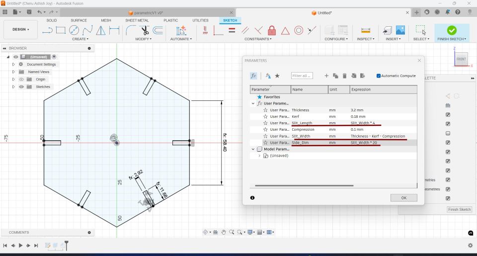
Here, I have set two set of parameters -
- Parameters Set without specified Side Length Parameters are set for Slit Width, Slit Length and Side Dimension. Side Dimension = Slit Width * 20
- Parameters Set with Side Length Parameters are set for Slit Width, Slit Length and Side Dimension. Side Dimension = 50 mm
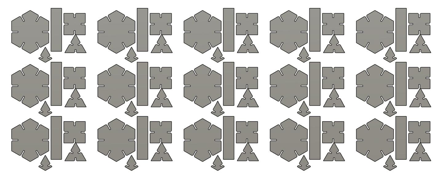
I designed the following shapes for my construction kit using the parameteres defined before.
Generating Multiple Parts and Preparing for Laser Cutting
After designing the basic parametric shapes, I used Fusion 360's Rectangular Pattern tool to efficiently duplicate each component, ensuring I had enough pieces for assembling the construction kit. This allowed me to create 15 copies of each shape while maintaining parametric constraints, meaning any design modifications would automatically update across all instances.
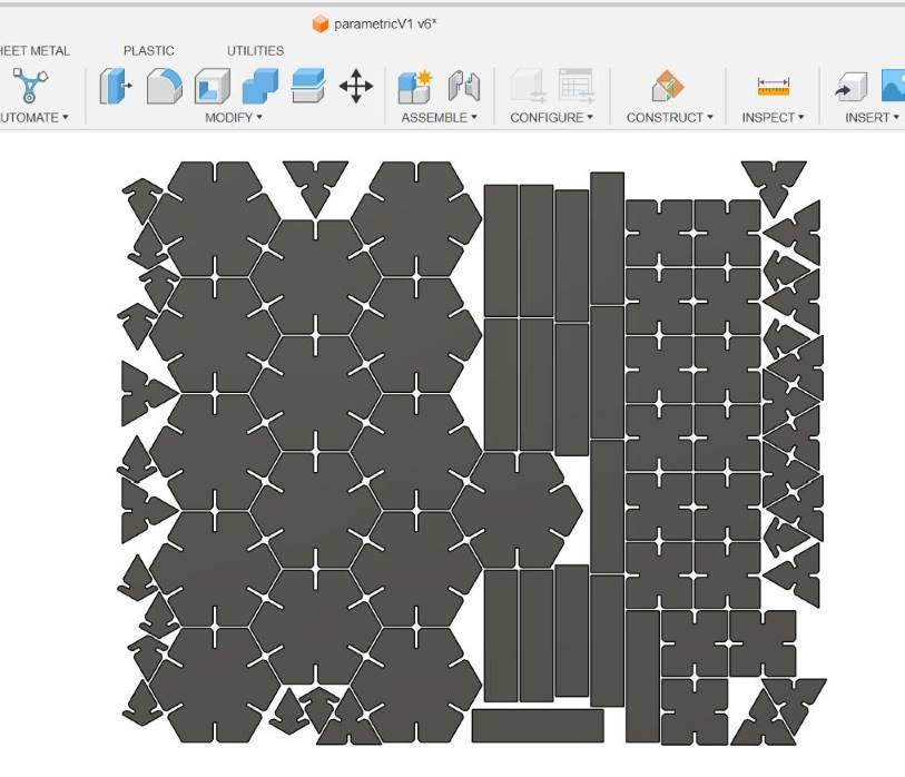
Arranging Components for Efficient Cutting
To optimize material usage, I utilized the Arrange tool in Fusion 360. This tool automatically positioned the parts within a specified area, ensuring minimal material waste and efficient laser cutting.
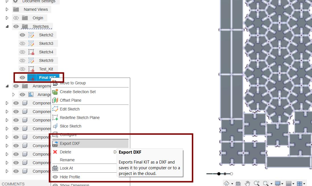
Exporting for Laser Cutting
Once the components were properly arranged, I projected them onto a new sketch and exported the design as a DXF file. This format is compatible with laser cutter software, ensuring precise cutting based on the parametric dimensions defined earlier.
Editing DXF File in Inkscape
The DXF File is imported into Inkscape and the Canvas is resized to fit all the selected components in the file using the shortcut
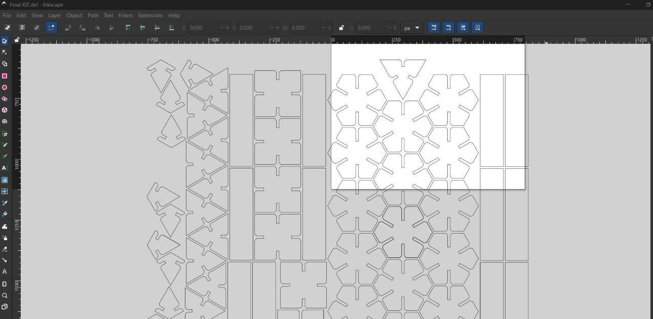
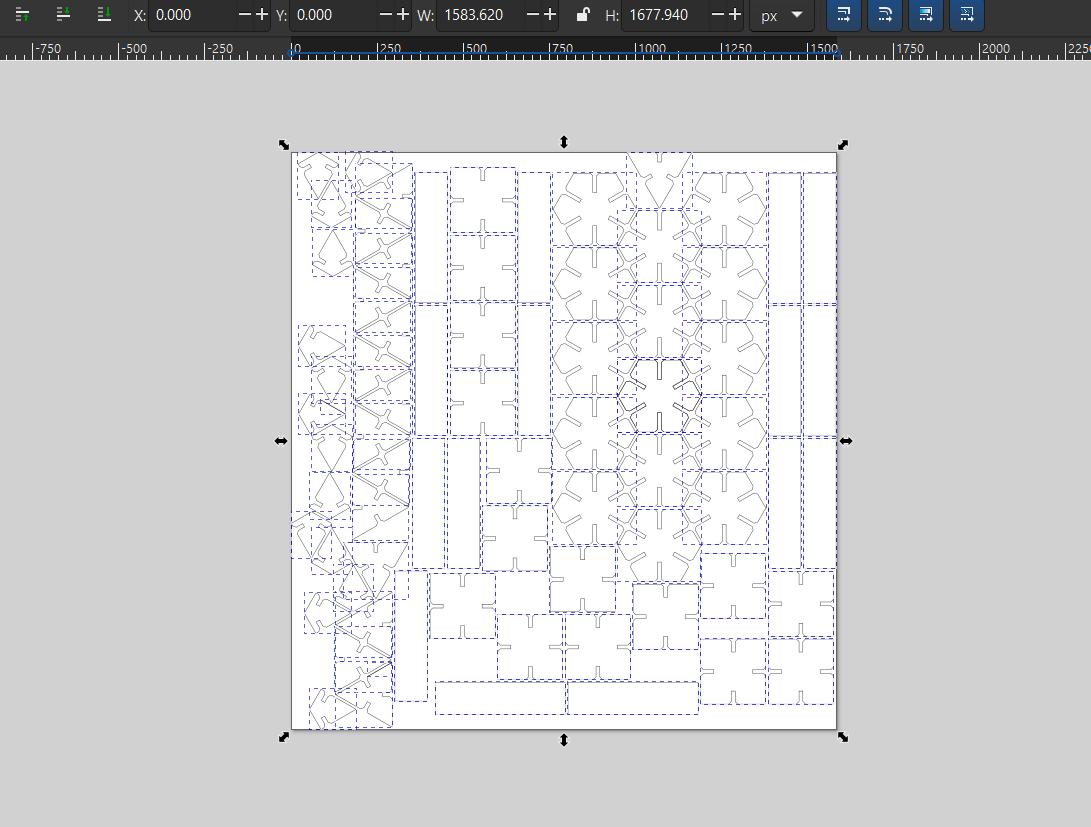
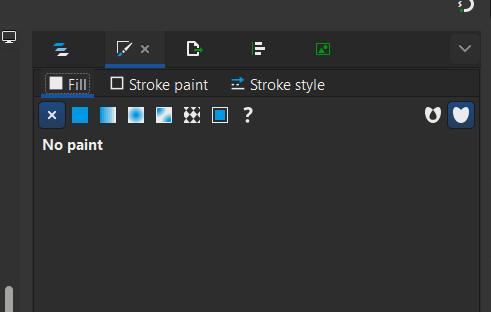
The Trotec Laser Cutter Software only takes strokes and no fills as input. Therefore, the fill mustt be set to no fill.
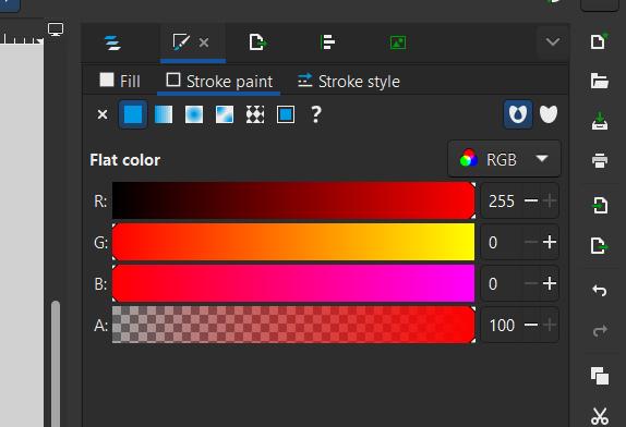
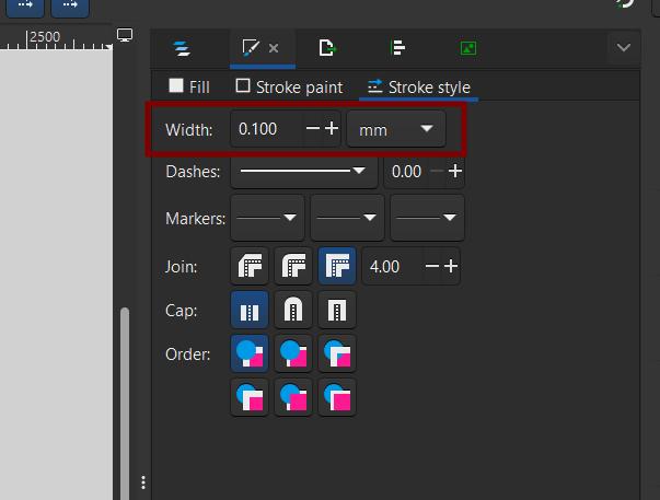
By convention, the stroke color is set to red for cutting paths and the stroke width must be 0.1 mm
The modified DXF File is set to Trotec software using print. The steps can be seen in the group documentation.
Cutting and assembling the pieces into different structures.
Once the design was finalized and send to the Trotec JobControl software using the print function, I proceeded with the laser cutting process in the following steps:
JobControl, which acts like a print driver for the laser cutter. Once the file was sent, I opened JobControl and dragged the newly received job from the plate preview list onto the virtual laser bed.
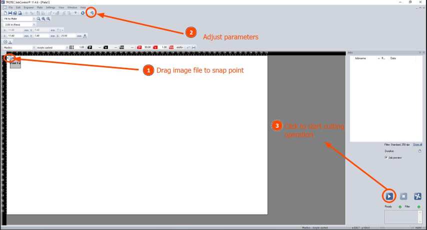
After properly placing it on the workspace, I double-checked the material settings such as power, speed, and frequency according to the type and thickness of the material I was using
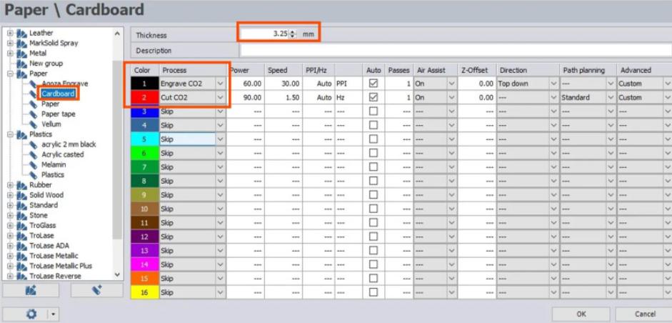
- Material: Cardboard
- Thickness: 3.20
- Engrave: NA
- Cut C02: Red
Parameter Value Process Cut CO₂ Power 90.00 Speed 1.50 PPI/Hz Auto (Hz) Auto Checked Passes 1 Air Assist On Z-Offset 0.00 Direction --- Path Planning Standard Advanced Custom
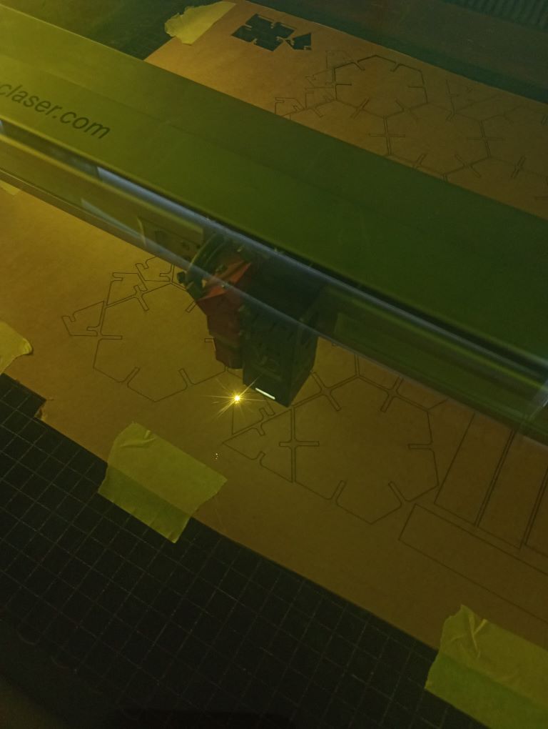
Once everything was aligned and settings verified, I switched to the laser cutter interface, ensured that the material was properly placed and focused, and then started the cutting job from JobControl.
Test Cutting Basic Shapes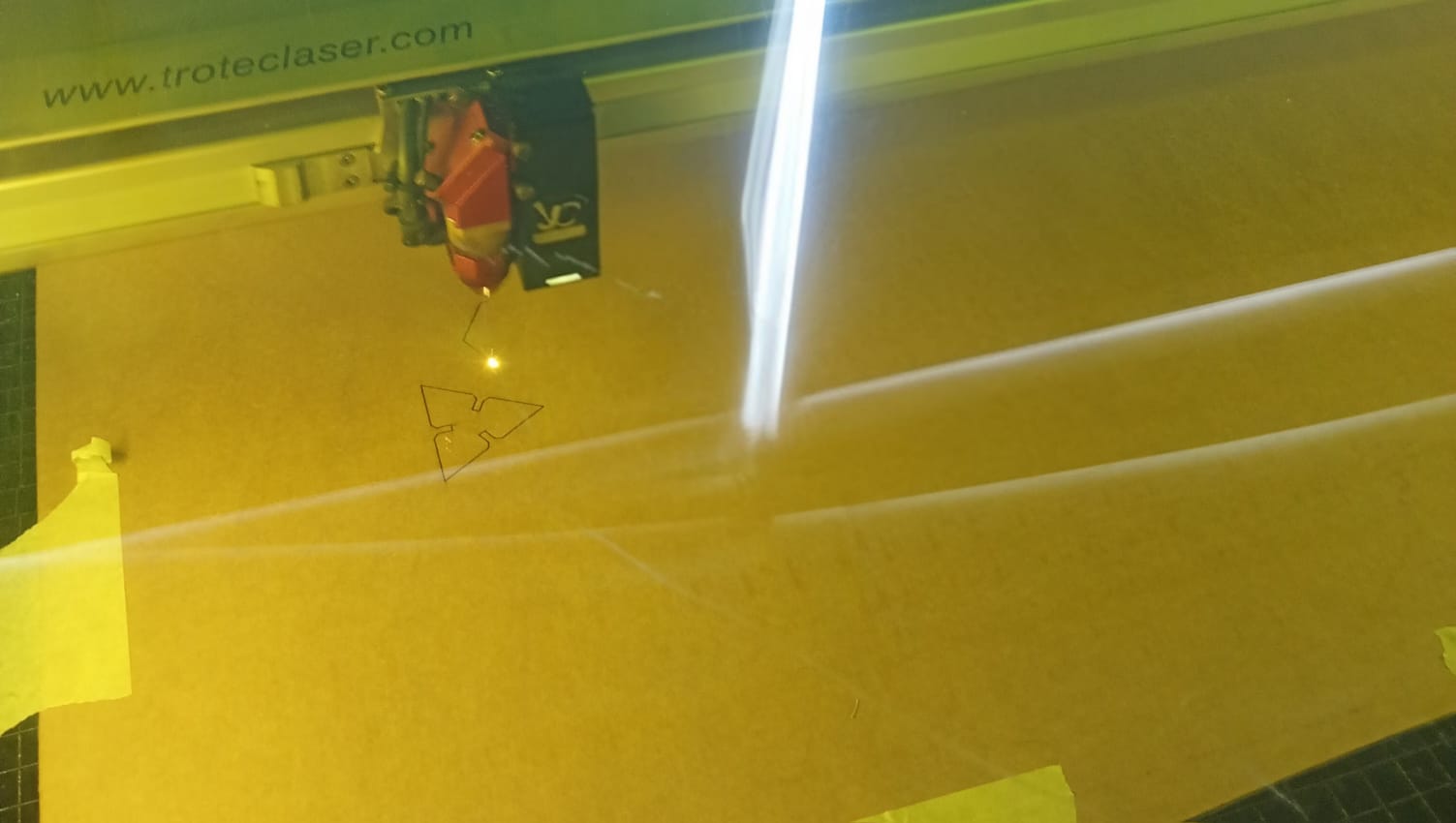
Before cutting the entire kit, I conducted a test cut using a few basic shapes. This step was crucial to:
Verify the kerf adjustment and ensure that the press-fit joints had the right level of snugness. Check the material response to laser power and speed settings to avoid charring or incomplete cuts. Make any necessary modifications to the slit width or other parameters based on the fit test results.
- Power: 90
- Speed: 1.25
- Passes: Ensured proper focus by using Auto Focus for a clean cut and used single
The laser cutting process successfully produced all the kit components with clean edges and precise interlocking slots.
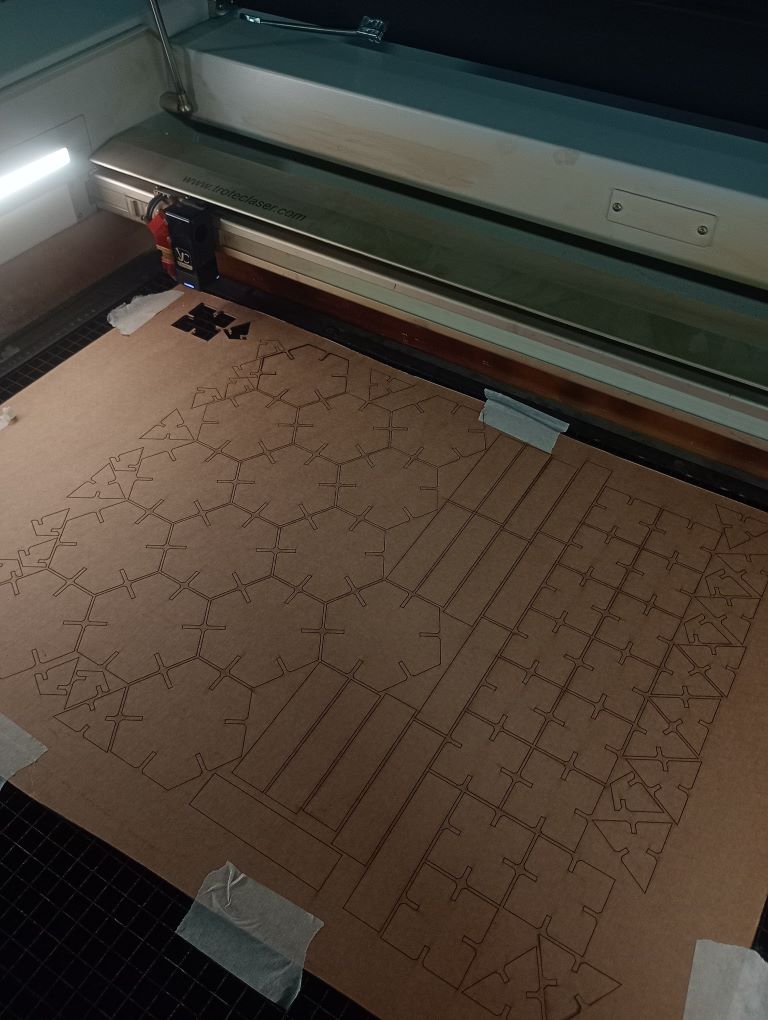
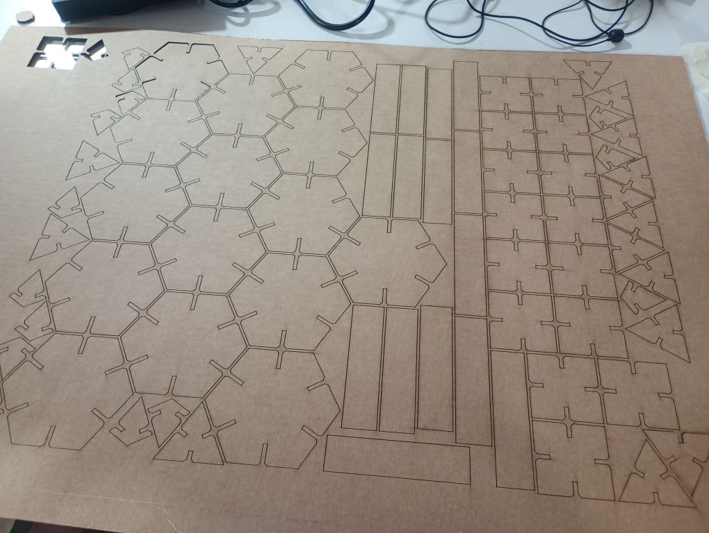
After cutting, I carefully removed the pieces from the laser bed, ensuring that no parts were left behind. The cut pieces were then organized for assembly.
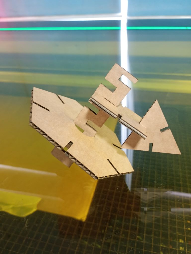
Assembling the Construction Kit
With all the components cut, I began assembling the construction kit. The design allowed for multiple configurations, enabling me to create various structures by interlocking the pieces together. The press-fit joints worked effectively, providing a secure connection without the need for additional adhesives or fasteners.
Here are some of the structures I created using the kit:
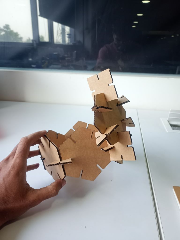
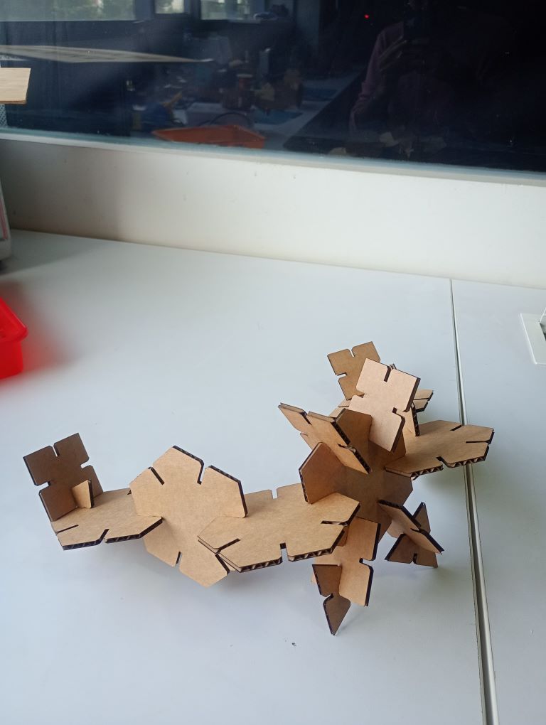
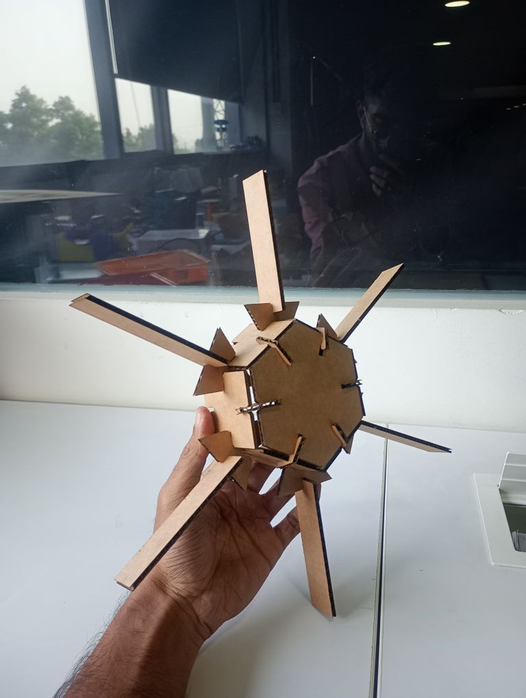
These variations demonstrate the versatility of the parametric design, allowing for creative exploration and assembly possibilities. The kit's modular nature enables easy reconfiguration and encourages experimentation with different structures.
Overall, this assignment provided valuable insights into parametric design, laser cutting techniques, and the practical application of creating a construction kit. I look forward to further exploring the potential of parametric modeling in future projects.
Design Files
You can download my design files from below
Vinyl Cutting
Parametric Kit