
System Integration
This week focused on the integration and planning of all the different parts of the project ranging from: User Flow, Functionality, Design, Production, Testing, Failures. I have tried to decide and list as many fixed processes and features as possible.

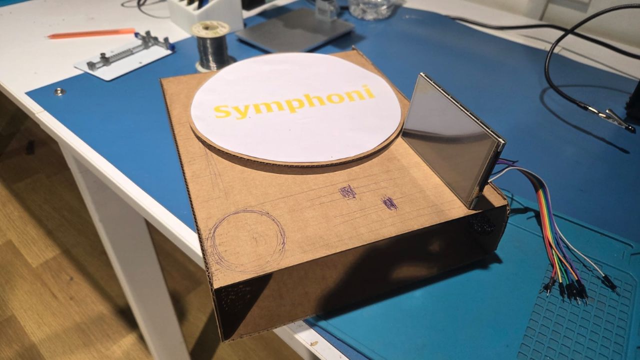
User Flow
The user interaction with Symphoni begins by determining whether the NFC "record" has already been written with a Spotify playlist or track link. If a record has already been written, the user can simply place it on the Symphoni player. The embedded system reads the NFC tag, retrieves the Spotify link, and initiates playback through a connected Bluetooth speaker. Playback controls such as play/pause, skip, and volume adjustment can be handled directly through capacitive buttons or sliders integrated into the player's interface, offering a tactile and intuitive experience.

If the record is blank or unwritten, the user must first open the Spotify app on their mobile device and locate the desired track, album, or playlist. They can then either copy the share link or use Spotify's “Share to App” feature to send it directly to the Symphoni companion Flutter app. Within the app interface, the user pastes or confirms the link and then writes it to the NFC record by bringing it close to the phone. Once the record is written, it is ready for use and can be placed on the player to function as described earlier.
This simple flow bridges the digital and physical worlds—turning Spotify playlists into tangible objects that trigger music playback through physical interaction. The system is designed to be modular and user-friendly, with potential expansion features like magnetic levitation for visual appeal and a multifunctional display unit that may also serve as a wireless charging dock for smartphones.
Functionality Diagram
The Symphoni system is architected around two main subsystems: the primary device and the Bluetooth speaker module, both coordinated via ESP32 WROOM microcontrollers. The central device integrates a rotary encoder that serves as a mode selector, an NFC tag reader/writer to read records, a DC motor for motion (potentially for rotation or levitation), and an SPI TFT display for visual feedback. These components are managed by an ESP32 WROOM, which acts as the main controller of the hardware unit. A Flutter mobile app interfaces with this system via HTTP requests, allowing users to write playlist data to NFC records and send control commands to the player.

The Bluetooth speaker module is designed to receive audio data from the mobile or any spotify connect device. It is equipped with a Bluetooth receiver and an audio amplifier, which are also controlled by an ESP32 WROOM. This module can be powered independently or through the main device, depending on the design choices made during the development phase.
On the speaker side, another ESP32 WROOM handles audio playback and user inputs. It receives control signals from physical buttons (for previous, play/pause, next, and input selection) and a volume control encoder. Audio output is handled via an I2S DAC that feeds into an amplifier and subsequently a speaker, delivering high-quality sound. The two ESP32 modules communicate wirelessly to synchronize playback and control operations, enabling a seamless and interactive user experience that bridges mobile app control, physical interaction, and digital music playback.
Schedule
The schedule for the project is divided into three main phases: Conceptual, Detailed, and Final. The first phase focuses on defining the core features and user experience, including NFC integration and basic audio playback. The second phase involves detailed design and prototyping, including the modular display and wireless charging capabilities. The final phase will focus on testing, refinement, and preparing for production.

Bill of Materials
| Item | Quantity | Price | Link |
|---|---|---|---|
| PCM5102 I2S DAC - 3.5mm Stereo Out | 1 | 500 | hubtronics |
| TPA3116D2 Audio Dual Channel Stereo Digital Amplifier Board | 1 | 417 | Robu |
| 8 Ohm Speakers | 2 | ||
| Sliding Adjustable Potentiometer Module 10k | 3 | 120 | Robu |
| Rotary Encoder Module | 1 | 50 | Robu |
| ESP32-WROOM-32 | 1 | 500 | Robu |
| Item | Quantity | Price | Link |
|---|---|---|---|
| ESP32-WROOM-32 | 1 | 500 | Robu |
| RC522 Module with RFID Card and Tag | 1 | 285 | Amazon |
| Rotary Encoder Module | 1 | 50 | Robu |
| DC Motor | 1 | ||
| 2.8" SPI TFT Display | 1 | 800 | Robu |
| Mechanical Switch Buttons | 4 | ||
| WS2812B LEDs | 10 | ||
| Buck Converter | 1 | Robu |
Functions
The Symphoni system is designed to be modular and user-friendly, with a focus on seamless interaction between the hardware and software components. The main functions include:
- Bluetooth Audio Playback: The system connects to Bluetooth speakers for audio output.
- Spotify Playback using Records: Users can play Spotify tracks through NFC-enabled records.
- NFC Tag Reading: The system reads NFC tags embedded in records to retrieve Spotify links.
- Playback Controls: Users can control playback and volume through buttons and knobs.
- Frequency Modualtion The slider potentiometers allows users to manipulate bass,mid and treble
- Track Display The display serves as a visual interface to view track info
- Mode Control The rotary encoder allows users to select different modes or tracks.
- Companion App The Android App allows to write the Records with any track, albums or playlists.
- NFC Carder Reading
- Fetching and Playing from Spotify
- Bluetooth Speaker Functionality
- Flutter Companion App
- Enclosure Design
- Rotating Platter Design
- Display Mount Design
- Finish and Texture
- MCU Pins: The pins required may outgrow XIAO ESP32C6. That's why I planned to use ESP32-WROOM-32 or use I2C expanders.
- Display Dock: Modular display doubles as wireless phone charger.
- Levitation: Start with DC motor. Leave physical space for magnetics in later spirals.
- Main Board: A ESP32 based board which can implement Spotify API Integration, Display, Playback Control, Motor Control
- Speaker Board: A ESP32 based board which can implement Bluetooth Speaker Functionality connect to a amplifier which is connected to speakers
- Power Management Board: A board that takes 12V input and distributes 12V and 5V to the system
- Playback Controls:* A board that has the playback buttons which is connected to the main board.
Design
Symphoni is a modular, NFC-enabled turntable that levitates records. It features a wireless charging display and a capacitive touch interface. The design emphasizes user experience, with seamless NFC interactions and clear track information.
I have created an mood/inspiration board for my design and included elements that I want to include in my project

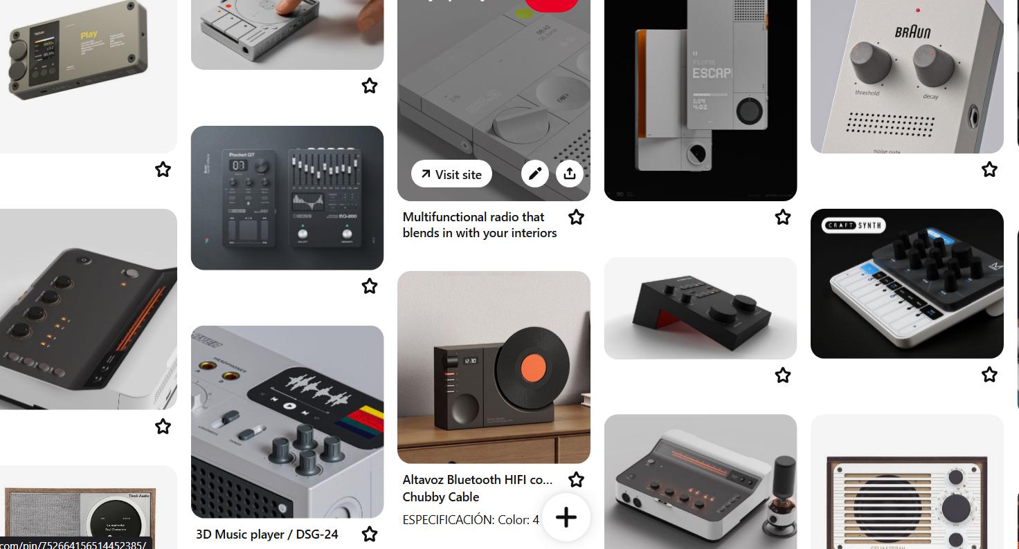
The inspiration board consists of various elements I want in my project: Color Palette, Texture, Dot LED Style Matrix, Display Style, Buttons and Slider Interfaces
I wanted to achieve the Dot Matrix Display Style for my Speaker so I tried a SVG Generator called Vertigo for this
Vertigo: Dot Matrix SVG GeneratorI uploaded the 'SYMPHONI' text on the SVG Generator and got the required effect and modified it in inkscape and used the Trotec Laser Cutter to get the front panel
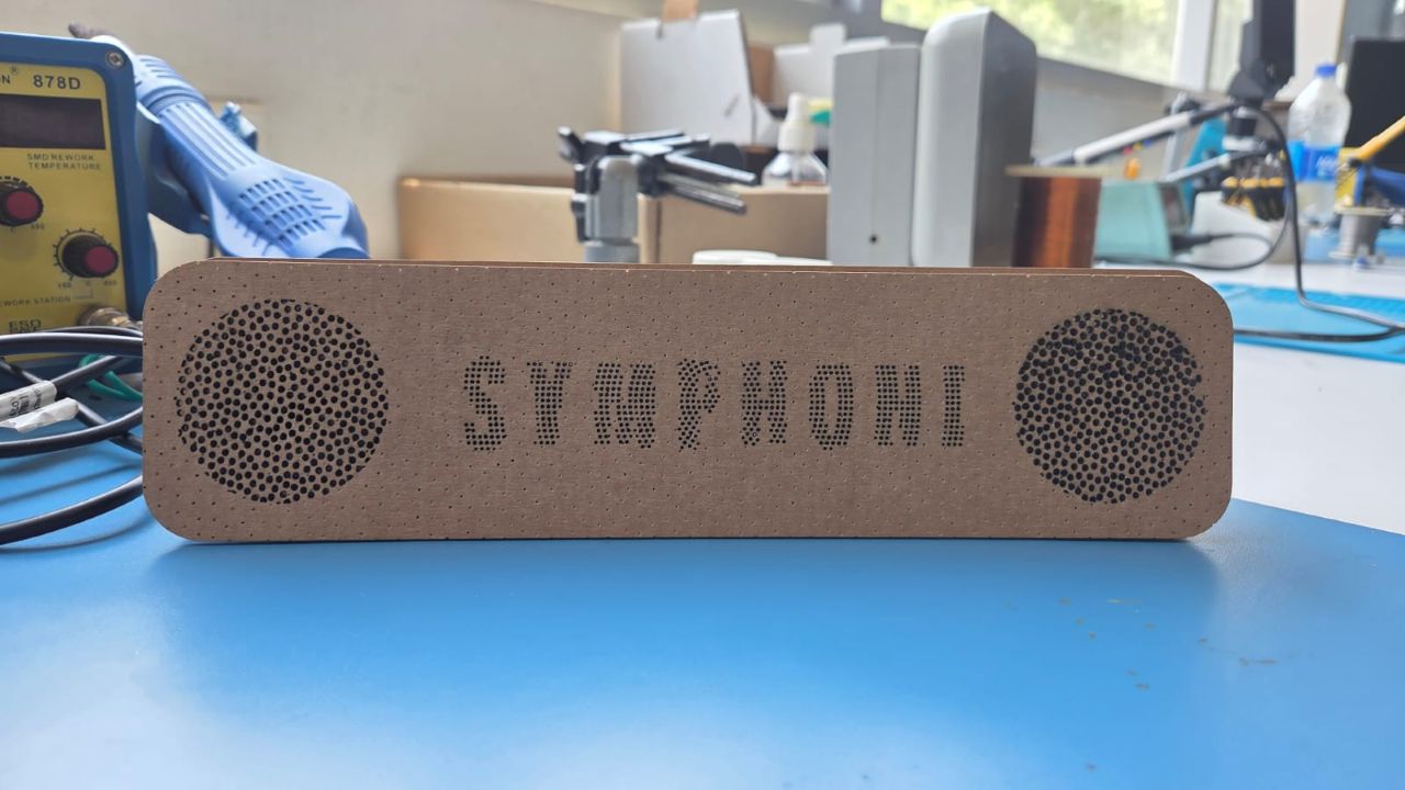
The above front panel layout is what the user sees, the SYMPHONI logo will be lit using a backlight while the round areas will hide the speakers yet allow audio transmission through them. This is something that I wanted in my product

This layer allows for the speakers to be mounted on them and then the front panel can be placed on top of it.

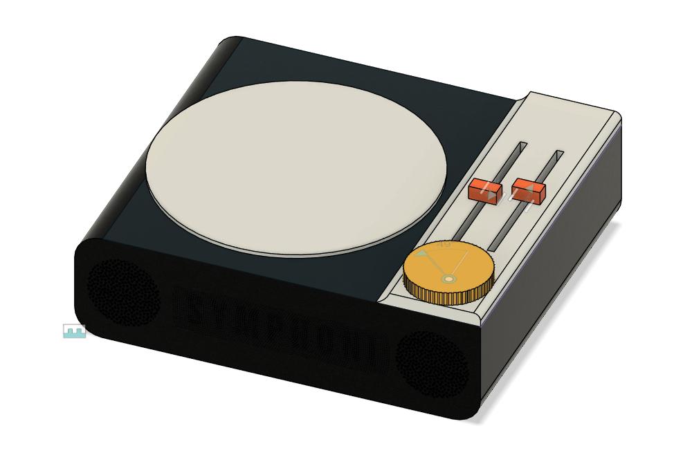
Basic Button Layout
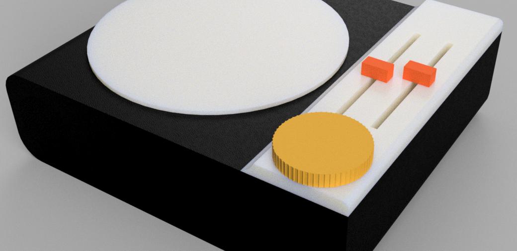
The top view of the Record Player would look something like this


The above mockup is a basic representation of how the final product would look like. The buttons and sliders are placed in a way that they are easily accessible to the user. The display is placed at an angle for better visibility. The overall design is sleek and modern, with a focus on user experience.
Renders of the Design
The design has been created in Fusion 360 and rendered using the inbuilt rendering tool. The material used is a combination of wood and plastic. The wood gives a premium look while the plastic makes it lightweight and durable. The overall design is sleek and modern, with a focus on user experience.


These images showcase different angles and perspectives of the Symphoni design, highlighting its sleek and modern aesthetic. The combination of wood and plastic materials gives it a premium look while ensuring durability and lightweight construction. The placement of buttons, sliders, and display is designed for optimal user experience, making it easy to interact with the device.
What has been Done
So far, I have tested the following:
What needs to be done
In the next few weeks, I will be focusing on the following:
Notes & Decisions
Elctronic Systems
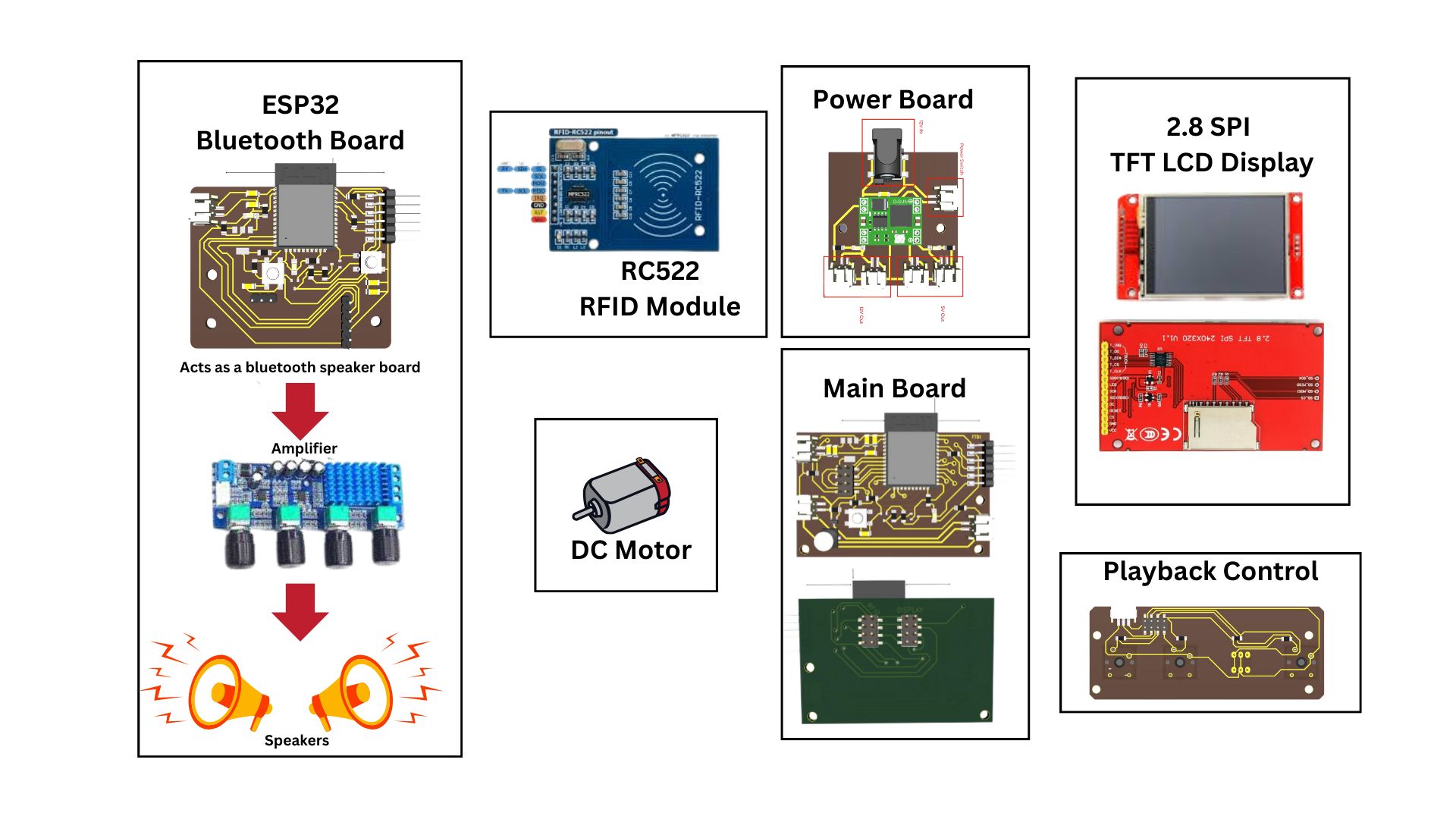
Symphoni is built around a modular four-board architecture, where each PCB is responsible for a specific task. The system comes together through carefully designed interconnections using IDC connectors and a shared power distribution network.
There are mainly 4 different PCBs that I need to produce for the project.
System Integration - Electronics and Wiring
The wiring of the Symphoni system connects all major modules—main board, speaker board, power management, and playback controls—using IDC connectors for reliable and modular assembly. Each board receives power from the central power management PCB, which distributes both 12V and 5V as needed. Signal lines for Playback Control, RFID module, and display are routed via ribbon cables to minimize clutter and simplify maintenance.
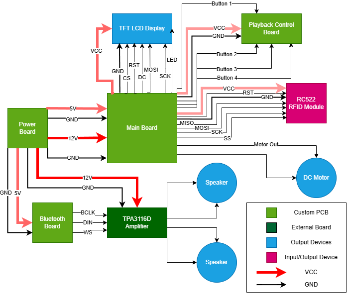
This approach ensures that each subsystem can be easily replaced or upgraded, and helps with troubleshooting by keeping connections organized and accessible. All wiring is color-coded and labeled for clarity during assembly and repair.
The below diagram shows the wires that I am going to use for each connection. The power lines are 1x2 JST connectors whcih power the two main boards and also provide the 12V to the motor and the amplifier. The other connections to the RC522 RFID module, the display and the playback controls are done using IDC connectors and ribbon cables.
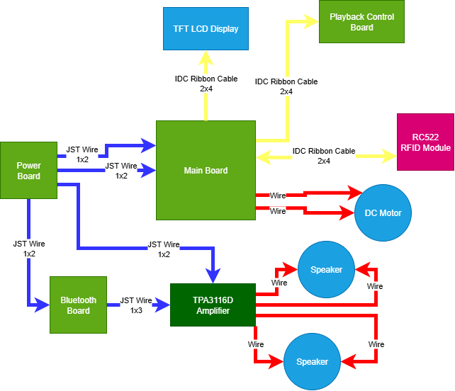
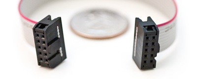
Photo credit: IQSdirectory
The above image shows the IDC connector that I will be using for my project. The ribbon cable makes it easy to connect multiple wires in a single connector and also makes it easy to disconnect and reconnect the wires.
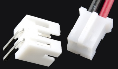
Photo credit: IQSdirectory
The above image shows the JST connector that I will be using for my project. The JST connector is a two pin connector which is used to power the boards. The red wire is for positive voltage and the black wire is for ground.
The wiring is done in a way that it is easy to assemble and disassemble the system. The IDC connectors make it easy to connect and disconnect the wires and the JST connectors make it easy to power the boards. The wiring is also done in a way that it is easy to troubleshoot and repair the system.
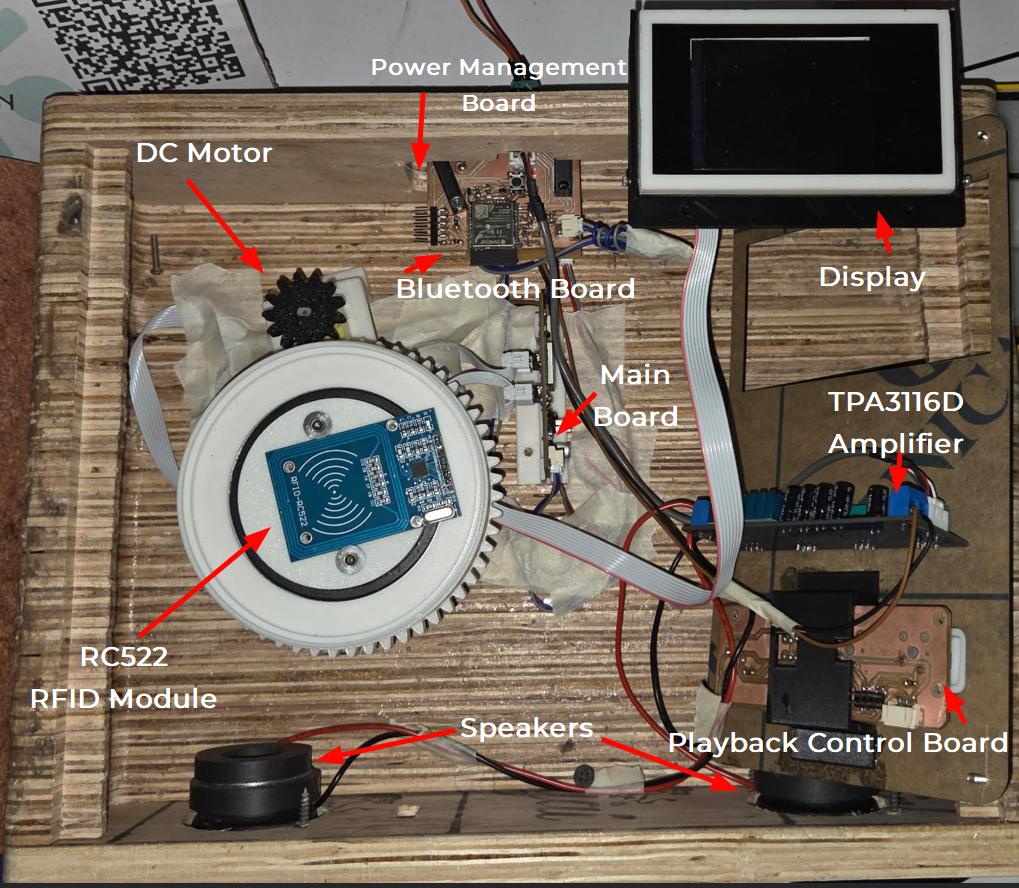
This is how the inside of the enclosure looks like without wiring the speakers and the display. The Motor, RFID Reader and the PCB Boards are mounted on the Enclosure base.
The final wiring and integration looks like the below picture.
Design Files
You can download my design files from below