
Mechanical Design, Machine Design
This week, I focused on understanding the workings of a machine and program the electronic system of a CNC consisting of the firmware and ESP NOW connection.
Learning Objectives
Assignments
Group Assignments
Individual Assignments
Group Assignment
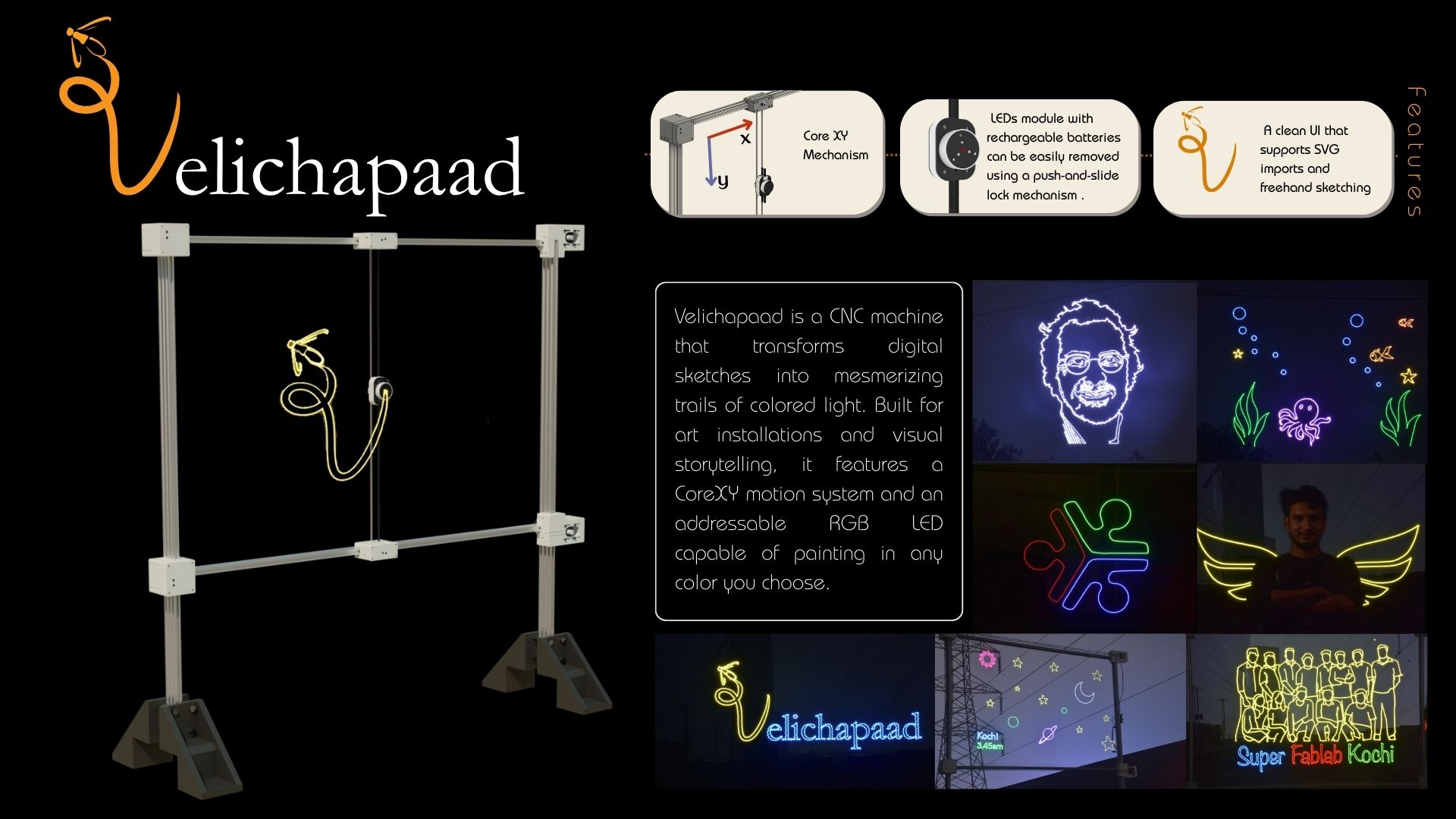
Velichapad is a CNC Light Painting machine which uses the CORE XY Mechanism and ESP32 GRBL Controller Board. It allows us to draw custom drawing or upload files and choose colors for strokes and convert them to G-Code, which can be sent to the Machine. The below links to the machine documentation.
Group AssignmentI had the responsibility to mannage the elctronics, firmware and communciation of the machine. I used the GrblEsp32 Firmware and modified it for our machine. I also programmed the communication between the main controller board to a wireless XIAO ESP32 device using ESP-NOW.
The below video shows some light painitngs and stop motion videos we made using the painting frames.
Brainstorming session
As part of the machine design week planning, we had a brainstorming session which helped us to come up with the idea of 'Velichapad - The Light Painting Machine'. After deciding the project idea, Revisankar took charge of planning the project development and everyone delegated and took responsibility of varous tasks for completting the assignment in the limited time we had. The below iamge shows the task distribution table.

I took the responsibility of the electronics and programming of the machine, which included the light module, the firmware, UI/UX and the controller electronics.
The major electronics parts included:
- CNC Controller Board
- Stepper Motors and Drivers
- Wirelles Light Module
- ESP-NOW Communication
- Firmware for the CNC Controller
- UI/UX for the controller
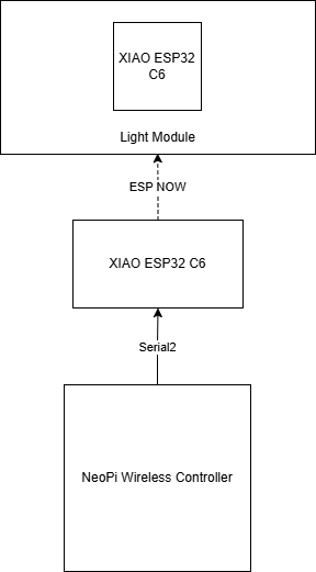
For the Wireless Light Module, we needed a PCB to be designed and produced to act as the end effector of the machine. Namita had the responsibility to design and produce the PCB for the light module. The module would have a XIAO ESP32 C6 at its core connected to a series of WS2812B LEDs powered by a battery unit. As the module would have a ESP32 C6 and the main controller board we were using was NeoPI Wireless CNC Controller, designed by our instructor Saheen, had a ESP32 Module at it's core, ESP-NOW was the best solution for the wireless communication. Therefore, I decide to explore ESP-NOW and it's communication with the main ESP32 board.
As Namita was designing and producing the Light Module, I decide to test the ESP-NOW Communication using my AXIAO Board and a ESP32 Dev Module I had.
The below block diagram shows the communication between the controller and the XIAO ESP32 C6.
ESP-NOW WS2812B LED Control
ESP-NOW is a wireless communication protocol defined by Espressif, which enables the direct, quick and low-power control of smart devices, without the need of a router. ESP-NOW can work with Wi-Fi and Bluetooth LE, and supports the ESP8266, ESP32, ESP32-S and ESP32-C series of SoCs. It's widely used in smart-home appliances, remote controlling, sensors, etc.
Getting Started with ESP-NOWTo communicate via ESP-NOW, you need to know the MAC Address of the ESP32 receiver. That's how you know to which device you'll send the data to. Each ESP32 has a unique MAC Address and that's how we identify each board to send data to it using ESP-NOW
/*
Rui Santos & Sara Santos - Random Nerd Tutorials
Complete project details at https://RandomNerdTutorials.com/get-change-esp32-esp8266-mac-address-arduino/
Permission is hereby granted, free of charge, to any person obtaining a copy of this software and associated documentation files.
The above copyright notice and this permission notice shall be included in all copies or substantial portions of the Software.
*/
#include
#include

void readMacAddress(){
uint8_t baseMac[6];
esp_err_t ret = esp_wifi_get_mac(WIFI_IF_STA, baseMac);
if (ret == ESP_OK) {
	Serial.printf("%02x:%02x:%02x:%02x:%02x:%02x\n",
				baseMac[0], baseMac[1], baseMac[2],
				baseMac[3], baseMac[4], baseMac[5]);
} else {
	Serial.println("Failed to read MAC address");
}
}

void setup(){
Serial.begin(115200);

WiFi.mode(WIFI_STA);
WiFi.STA.begin();

Serial.print("[DEFAULT] ESP32 Board MAC Address: ");
readMacAddress();
}

void loop(){

}
For better understanding, we'll call “sender” to ESP32 #1 and “receiver” to ESP32 #2.
Here's what we should include in the sender sketch:
- Initialize ESP-NOW;
- Register a callback function upon sending data - the OnDataSent function will be executed when a message is sent. This can tell us if the message was successfully delivered or not;
- Add a peer device (the receiver). For this, you need to know the receiver MAC address;
- Send a message to the peer device.
On the receiver side, the sketch should include:
- Initialize ESP-NOW;
- Register for a receive callback function (OnDataRecv). This is a function that will be executed when a message is received.
- Inside that callback function, save the message into a variable to execute any task with that information.
typedef struct structName {
	type member1;
	type member2;
	// ...
} typedefName;
Serial.println(status == ESP_NOW_SEND_SUCCESS ? "Delivery Success" : "Delivery Fail");This is a ternery operator,replacing if-else statement. If the status is successful, then print 'Delivery Success' else print 'Delivery Fail'
ESP32 Sender Code
/*
	Rui Santos & Sara Santos - Random Nerd Tutorials
	Complete project details at https://RandomNerdTutorials.com/esp-now-esp32-arduino-ide/
	Permission is hereby granted, free of charge, to any person obtaining a copy of this software and associated documentation files.
	The above copyright notice and this permission notice shall be included in all copies or substantial portions of the Software.
  */
  #include
  #include

  // REPLACE WITH YOUR RECEIVER MAC Address
  uint8_t broadcastAddress[] = {0xFF, 0xFF, 0xFF, 0xFF, 0xFF, 0xFF};

  // Structure example to send data
  // Must match the receiver structure
  typedef struct struct_message {
	char a[32];
	int b;
	float c;
	bool d;
  } struct_message;

  // Create a struct_message called myData
  struct_message myData;

  esp_now_peer_info_t peerInfo;

  // callback when data is sent
  void OnDataSent(const uint8_t *mac_addr, esp_now_send_status_t status) {
	Serial.print("\r\nLast Packet Send Status:\t");
	Serial.println(status == ESP_NOW_SEND_SUCCESS ? "Delivery Success" : "Delivery Fail");
  }

  void setup() {
	// Init Serial Monitor
	Serial.begin(115200);

	// Set device as a Wi-Fi Station
	WiFi.mode(WIFI_STA);

	// Init ESP-NOW
	if (esp_now_init() != ESP_OK) {
	  Serial.println("Error initializing ESP-NOW");
	  return;
	}

	// Once ESPNow is successfully Init, we will register for Send CB to
	// get the status of Trasnmitted packet
	esp_now_register_send_cb(OnDataSent);

	// Register peer
	memcpy(peerInfo.peer_addr, broadcastAddress, 6);
	peerInfo.channel = 0;
	peerInfo.encrypt = false;

	// Add peer
	if (esp_now_add_peer(&peerInfo) != ESP_OK){
	  Serial.println("Failed to add peer");
	  return;
	}
  }

  void loop() {
	// Set values to send
	strcpy(myData.a, "THIS IS A CHAR");
	myData.b = random(1,20);
	myData.c = 1.2;
	myData.d = false;

	// Send message via ESP-NOW
	esp_err_t result = esp_now_send(broadcastAddress, (uint8_t *) &myData, sizeof(myData));

	if (result == ESP_OK) {
	  Serial.println("Sent with success");
	}
	else {
	  Serial.println("Error sending the data");
	}
	delay(2000);
  }
ESP32 receiver Code
	/*
  Rui Santos & Sara Santos - Random Nerd Tutorials
  Complete project details at https://RandomNerdTutorials.com/esp-now-esp32-arduino-ide/
  Permission is hereby granted, free of charge, to any person obtaining a copy of this software and associated documentation files.
  The above copyright notice and this permission notice shall be included in all copies or substantial portions of the Software.
*/

#include
#include

// Structure example to receive data
// Must match the sender structure
typedef struct struct_message {
    char a[32];
    int b;
    float c;
    bool d;
} struct_message;

// Create a struct_message called myData
struct_message myData;

// callback function that will be executed when data is received
void OnDataRecv(const uint8_t * mac, const uint8_t *incomingData, int len) {
  memcpy(&myData, incomingData, sizeof(myData));
  Serial.print("Bytes received: ");
  Serial.println(len);
  Serial.print("Char: ");
  Serial.println(myData.a);
  Serial.print("Int: ");
  Serial.println(myData.b);
  Serial.print("Float: ");
  Serial.println(myData.c);
  Serial.print("Bool: ");
  Serial.println(myData.d);
  Serial.println();
}

void setup() {
  // Initialize Serial Monitor
  Serial.begin(115200);

  // Set device as a Wi-Fi Station
  WiFi.mode(WIFI_STA);

  // Init ESP-NOW
  if (esp_now_init() != ESP_OK) {
    Serial.println("Error initializing ESP-NOW");
    return;
  }

  // Once ESPNow is successfully Init, we will register for recv CB to
  // get recv packer info
  esp_now_register_recv_cb(esp_now_recv_cb_t(OnDataRecv));
}

void loop() {

}
ESP32 MCODE(Color) Sender
This code sends what brush size to select - 1,2,3 with 3 colors to select - RED, GREEN, BLUE.
- M051 - Brush 1
- M052 - Brush 2
- M053 - Brush 3
- M054 - LED OFF
By default, the LED will be RED. You can add color parameters with the M Code to select color(RED, GREEN, BLUE). For. eg. M051 GREEN
Upon further development I realised that it would be difficult to add custom code from the Firmware side.
So I decided to use the ESP-NOW to send the M Code and Color to the receiver module. The below code is the sender code which sends the M Code and Color in DEC format.
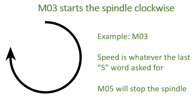
I used the standard M3 and M5 commands to turn ON and OFF the led. And the S parameter which is usually used to mention the Spindle Speed to determine the light color. For eg. M3 S255 would light up the led in red color, as 255 is the decimal conversion of color red.
ESPNOW Sender Code
This code allows the ESP32 to send M3 and M5 commands by ESP-NOW to another ESP32. This is the final program, here the XIAO ESP32 C6 sends the M commands using ESP-NOW which it recieves serially from the ESP32 CNC Controller using Serial 0. That's why you can see the Serial input is given as 'Serial0.available' instead of 'Serial.available'. Also the ESP32 CNC Controller sends M Codes as M0 and M1 S. M5 in the gcode file means a M0 command is sent serially to the XIAO ESP32 C6. M3 S in the gcode file means M1 S code is sent to the XIAO ESP32 C6. The color is given as a decimal number along with S.
/*
  Rui Santos & Sara Santos - Random Nerd Tutorials
  Modified by Ashish & ChatGPT for improved serial handling and user interaction.
  Original: https://RandomNerdTutorials.com/esp-now-esp32-arduino-ide/
*/

#include <esp_now.h>
#include <WiFi.h>

// Replace with your receiver's MAC address
uint8_t broadcastAddress[] = {0x7c, 0x2c, 0x67, 0x64, 0xba, 0xf8};//7C:2C:67:64:BA:F8


typedef struct struct_message {
  int brushSize;
  uint32_t color;  // Decimal color value like 16777215
} struct_message;

struct_message led;

String receivedData = "";

esp_now_peer_info_t peerInfo;

// Optional: onboard LED pin for visual feedback (usually GPIO 2)
const int onboardLED = 2;

// Callback when data is sent
void OnDataSent(const uint8_t *mac_addr, esp_now_send_status_t status) {
  Serial.print("\r\nLast Packet Send Status:\t");
  Serial.println(status == ESP_NOW_SEND_SUCCESS ? "Delivery Success" : "Delivery Fail");

  // Blink onboard LED to indicate a send action
  digitalWrite(onboardLED, HIGH);
  delay(100);
  digitalWrite(onboardLED, LOW);
}

void setup() {

  // Init Serial Monitor
  Serial.begin(115200);

  Serial0.begin(115200);   // Hardware UART0 (RX0=GPIO3, TX0=GPIO1)
  WiFi.mode(WIFI_STA); // Set device as a Wi-Fi Station

  // Set onboard LED pin as output
  pinMode(onboardLED, OUTPUT);
  digitalWrite(onboardLED, LOW);

  // Info for user
  Serial.println("ESP-NOW Command Sender Initialized");
  Serial.println("Available Commands:");
  Serial.println("  - M3 S(Color in Decimal)");
  Serial.println("  - M5");

  Serial.println("Type your command and press Enter...\n");

  // Init ESP-NOW
  if (esp_now_init() != ESP_OK) {
    Serial.println("Error initializing ESP-NOW");
    return;
  }

  // Register callback for sent message
  esp_now_register_send_cb(OnDataSent);

  // Register peer
  memcpy(peerInfo.peer_addr, broadcastAddress, 6);
  peerInfo.channel = 0;
  peerInfo.encrypt = false;

  if (esp_now_add_peer(&peerInfo) != ESP_OK) {
    Serial.println("Failed to add peer");
    return;
  }
}

void loop() {
  if (Serial0.available()) {
    receivedData = Serial0.readStringUntil('\n');
    receivedData.trim();

    if (receivedData.length() == 0) return;

    int mIndex = receivedData.indexOf('M');
    int SIndex = receivedData.indexOf('S');

    String command = receivedData.substring(mIndex, SIndex);
    command.trim();
    command.toUpperCase();

    uint32_t colorValue = receivedData.substring(SIndex + 1).toInt();

    bool validCommand = false;

    if (command == "M1") {
      led.brushSize = 1;
      validCommand = true;
    } else if (command == "M0") {
      led.brushSize = 0;
      validCommand = true;
    }

    if (validCommand) {
      led.color = colorValue;

      esp_err_t result = esp_now_send(broadcastAddress, (uint8_t *)&led, sizeof(led));
      Serial.printf("Sending -> Brush Size: %d | Decimal Color: %u\n", led.brushSize, colorValue);
      Serial.println(result == ESP_OK ? "✅ Sent successfully!" : "❌ Failed to send");
    }
  }
}
ESPNOW Final Reciever Code
The below code allows the reciever module to recieve 2 commands: M3 S(Color in Decimal) for turning on light with the color mentioned in Decimal format and M5 for turning off the light. M3 and M5 are commands commonly used for turning spindle ON and OFF, respectively.
#include <esp_now.h>
#include <WiFi.h>
#include <Adafruit_NeoPixel.h>

#define PIN        0
#define NUMPIXELS  7

typedef struct struct_message {
  int brushSize;
  uint32_t color;  // Direct decimal color like 16777215
} struct_message;

struct_message ledData;

int lastBrushSize = -1;
int brush = 0;

Adafruit_NeoPixel pixels(NUMPIXELS, PIN, NEO_GRB + NEO_KHZ800);

// Callback when data is received
void OnDataRecv(const esp_now_recv_info_t *recvInfo, const uint8_t *incomingData, int len) {
  memcpy(&ledData, incomingData, sizeof(ledData));

  Serial.print("📥 Brush Size: ");
  Serial.println(ledData.brushSize);
  Serial.print("🎨 Decimal Color: ");
  Serial.println(ledData.color);
}

void setup() {
  Serial.begin(115200);
  WiFi.mode(WIFI_STA);

  Serial.print("Receiver MAC Address: ");
  Serial.println(WiFi.macAddress());

  if (esp_now_init() != ESP_OK) {
    Serial.println("❌ Error initializing ESP-NOW");
    return;
  }

  esp_now_register_recv_cb(OnDataRecv);

  pixels.begin();
  pixels.clear();
  pixels.show();
}

void loop() {
  if (ledData.brushSize != lastBrushSize || brush > 0) {
    lastBrushSize = ledData.brushSize;

    switch (ledData.brushSize) {
      case 1: brush = 1; break;
      case 2: brush = 4; break;
      case 3: brush = 7; break;
      default: brush = 0; break;
    }

    pixels.clear();

    if (ledData.brushSize == 1) {
      pixels.setPixelColor(0, ledData.color);

    } else if (ledData.brushSize == 2) {
      pixels.setPixelColor(0, ledData.color);
      pixels.setPixelColor(1, ledData.color);
      pixels.setPixelColor(4, ledData.color);
      pixels.setPixelColor(5, ledData.color);

    } else if (ledData.brushSize == 3) {
      for (int i = 0; i < NUMPIXELS; i++) {
        pixels.setPixelColor(i, ledData.color);
      }
    }

    pixels.show();

    Serial.print("✨ Lighting up ");
    Serial.print(brush);
    Serial.println(" pixels.");
  }
}
Neoπ Wireless CNC Controller (3-axis)
The NeoPi Wireless CNC Controller was designed by Saheen Palayi, our instructor. It offers a 3 Axis CNC Contoller which runs using the ESP32 as the Main Control Unit of the controller. We used the DRV8825 as motor drivers for the two motors.
Neoπ CNC Controller - DocumentationThe CNC Machine works on Core X Y Configuration.
Firmware
We used the GRBL ESP32 firmware for the CNC Controller. The GRBL ESP32 is a high-performance CNC controller firmware that runs on the ESP32 microcontroller. It supports various CNC machines and provides features like G-code parsing, motion control, and more.
For more information on how to install and use the GRBL ESP32 firmware, you can refer to the official documentation on GitHub.
Grbl ESP32To install the GRBL ESP32 firmware, you need to follow the instructions provided in the documentation. The installation process involves setting up the development environment, configuring the firmware for your specific machine, and uploading it to the ESP32 board.
We have to setup the repository in VSCode using PlatformIO, a user-friendly and extensible integrated development environment with a set of professional development instruments, providing modern and powerful features to speed up yet simplify the creation and delivery of embedded products.
To install PlatformIO IDE for VSCode, you can follow the below documentation provided by PltformIO.
PlatformIO IDE for VSCode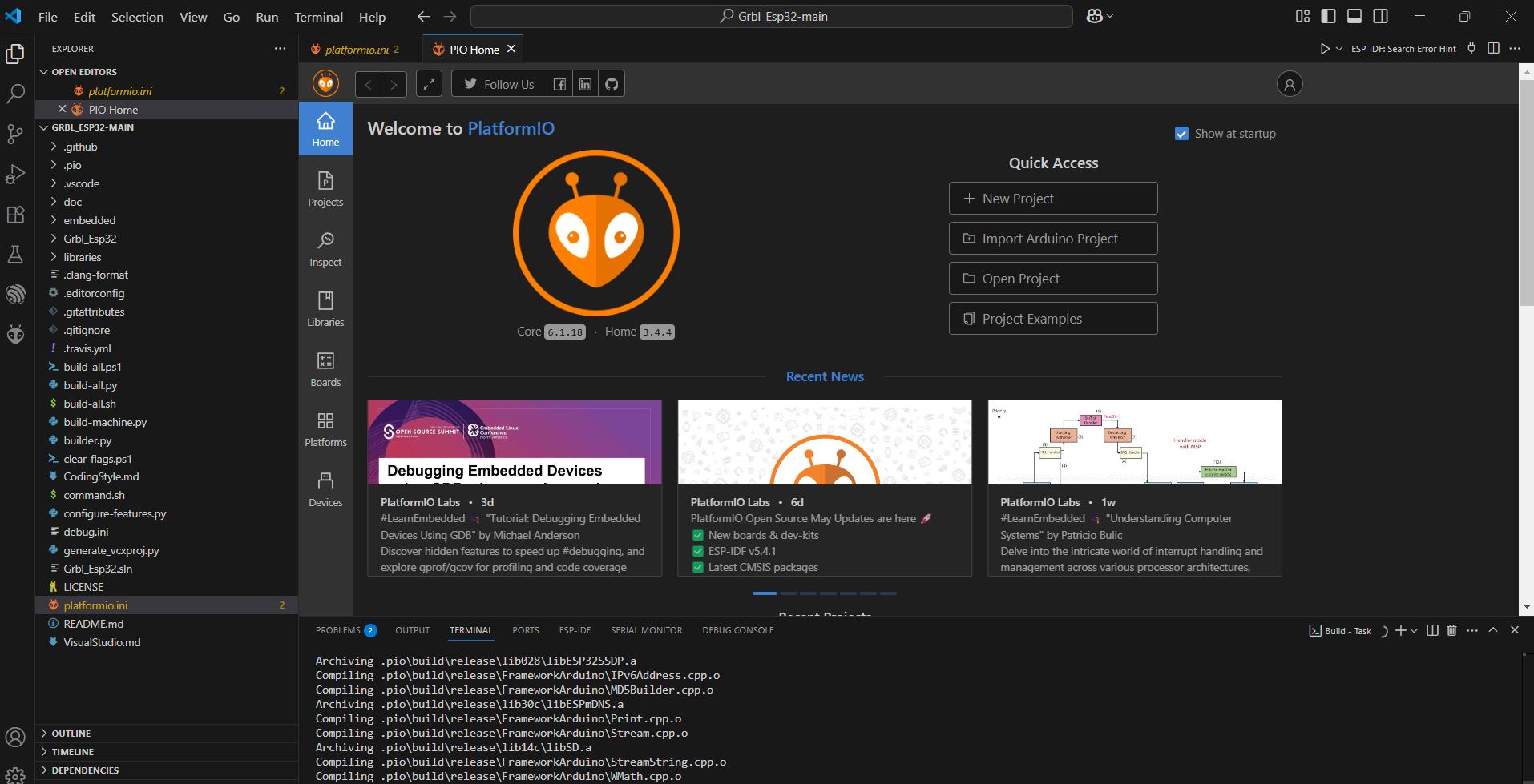
After initializing the repository and Platform IO, we need to make some modifications to the code for our machine.
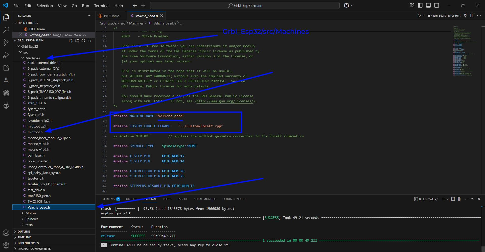
We need to add a new machine to the Grbl_Esp32/src/MAchines folder. We can use the midtbot machine configuration and just change the name and remove the line '#define MIDTBOT'. I named the machine file as 'Velicha_paad.h'. We have to mention the pinouts of the current ESP32 Controller Board
#define MACHINE_NAME "Velicha_paad"

#define CUSTOM_CODE_FILENAME    "../Custom/CoreXY.cpp"

// #define MIDTBOT         // applies the midTbot geometry correction to the CoreXY kinematics

#define SPINDLE_TYPE    SpindleType::NONE

#define X_STEP_PIN      GPIO_NUM_12
#define Y_STEP_PIN      GPIO_NUM_14

#define X_DIRECTION_PIN GPIO_NUM_26
#define Y_DIRECTION_PIN GPIO_NUM_25

#define STEPPERS_DISABLE_PIN GPIO_NUM_13

#define X_LIMIT_PIN     GPIO_NUM_21
#define Y_LIMIT_PIN     GPIO_NUM_4

#define Z_SERVO_PIN             GPIO_NUM_27

#define SPINDLE_TYPE SpindleType::NONE

// defaults
#define DEFAULT_HOMING_CYCLE_0      bit(Z_AXIS)
#define DEFAULT_HOMING_CYCLE_1      bit(X_AXIS)
#define DEFAULT_HOMING_CYCLE_2      bit(Y_AXIS)

#define DEFAULT_HOMING_DIR_MASK     (bit(X_AXIS) | bit (Z_AXIS)) // these home negative

#define DEFAULT_STEP_PULSE_MICROSECONDS 3
#define DEFAULT_STEPPER_IDLE_LOCK_TIME  255 // stay on

#define DEFAULT_STEPPING_INVERT_MASK    0 // uint8_t
#define DEFAULT_DIRECTION_INVERT_MASK   2 // uint8_t
#define DEFAULT_INVERT_ST_ENABLE        0 // boolean
#define DEFAULT_INVERT_LIMIT_PINS       1 // boolean
#define DEFAULT_INVERT_PROBE_PIN        0 // boolean

#define DEFAULT_STATUS_REPORT_MASK 1

#define DEFAULT_JUNCTION_DEVIATION  0.01 // mm
#define DEFAULT_ARC_TOLERANCE       0.002 // mm
#define DEFAULT_REPORT_INCHES       0 // false

#define DEFAULT_SOFT_LIMIT_ENABLE 0 // false
#define DEFAULT_HARD_LIMIT_ENABLE 0 // false1

#define DEFAULT_HOMING_ENABLE           1
#define DEFAULT_HOMING_FEED_RATE        500.0 // mm/min
#define DEFAULT_HOMING_SEEK_RATE        8000.0 // mm/min
#define DEFAULT_HOMING_DEBOUNCE_DELAY   250 // msec (0-65k)
#define DEFAULT_HOMING_PULLOFF          3.0 // mm

#define DEFAULT_X_STEPS_PER_MM 100.0
#define DEFAULT_Y_STEPS_PER_MM 100.0
#define DEFAULT_Z_STEPS_PER_MM 100.0 // This is percent in servo mode

#define DEFAULT_X_MAX_RATE 8000.0 // mm/min
#define DEFAULT_Y_MAX_RATE 8000.0 // mm/min
#define DEFAULT_Z_MAX_RATE 5000.0 // mm/min

#define DEFAULT_X_ACCELERATION 200.0 // mm/sec^2. 200 mm/sec^2 = 720000 mm/min^2
#define DEFAULT_Y_ACCELERATION 200.0 // mm/sec^2
#define DEFAULT_Z_ACCELERATION 100.0 // mm/sec^2

#define DEFAULT_X_MAX_TRAVEL 100.0 // mm NOTE: Must be a positive value.
#define DEFAULT_Y_MAX_TRAVEL 100.0 // mm NOTE: Must be a positive value.
#define DEFAULT_Z_MAX_TRAVEL 5.0 // This is percent in servo mode

#define DEFAULT_X_HOMING_MPOS DEFAULT_Z_MAX_TRAVEL // stays up after homing
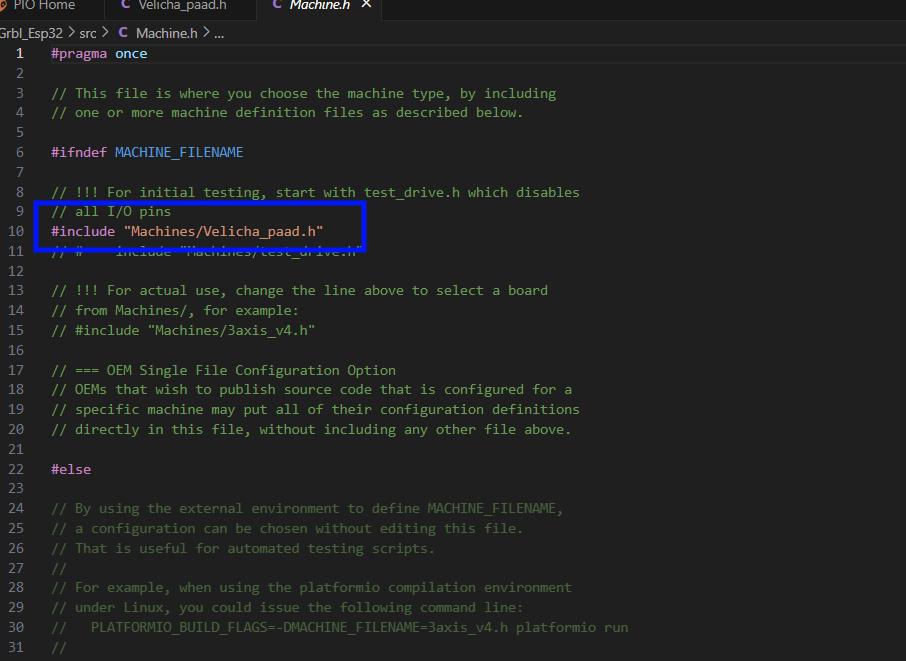
After adding the machine file in the machines folder, we need to add the name of the machine to the 'Machine.h' file #include "Machines/Velicha_paad.h"
	#pragma once

// This file is where you choose the machine type, by including
// one or more machine definition files as described below.

#ifndef MACHINE_FILENAME

// !!! For initial testing, start with test_drive.h which disables
// all I/O pins
#include "Machines/Velicha_paad.h"
Firmware - GRBL ESP32
After adding the machine we are set to customise our firmware to our needs. Now we need to set up sending serial messages to the XIAO ESP32C6 which will communicate to the XIAO ESP32C6 wirelessly on the light module.
We need to add custom RX and TX pins for our use case. So we'll edit the Serial.cpp and Serial.h files to send serial messages throught the custom pins 32 and 23.
Serial2.hIn this code, we will declare the RXD2 and TXD2
// Serial2Communication.h
#pragma once

// Define UART2 pins
#define RXD2 32
#define TXD2 22

// Function declarations
void initSerial2();
void sendMessage(const char* message);
In this code, we'll define the function sendMessage
#include "Serial2.h"
#include
#include "Grbl.h"

void initSerial2() {

    // Configure the UART2 port (Serial2)
    Serial2.begin(115200, SERIAL_8N1, RXD2, TXD2);
    delay(1000);  // Wait for the serial port to initialize
}

void sendMessage(const char* msg) {
    grbl_send(CLIENT_SERIAL, msg);
    Serial2.print(msg);
}
Spindle.h is located in GRBL_ESP32/src/Spindles
We need to add the sendMessage function when the M Code M3 and M5 are recieved. Therefore we added the function to the already existing code
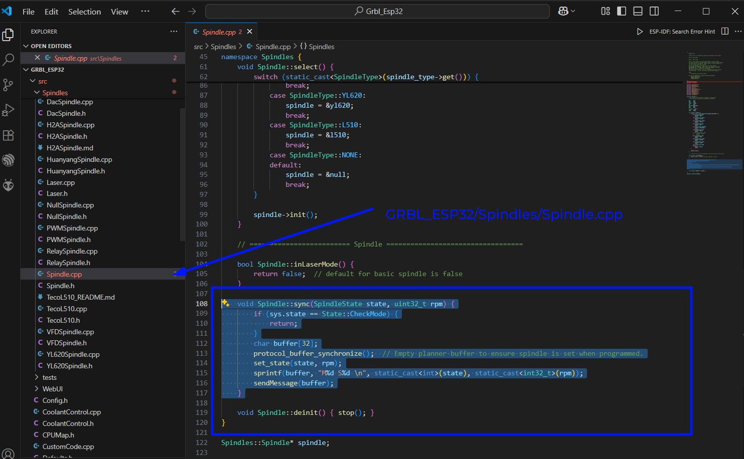
    void Spindle::sync(SpindleState state, uint32_t rpm) {
        if (sys.state == State::CheckMode) {
            return;
        }
        char buffer[32];
        protocol_buffer_synchronize();  // Empty planner buffer to ensure spindle is set when programmed.
        set_state(state, rpm);
        sprintf(buffer, "M%d S%d \n", static_cast(state), static_cast(rpm));
        sendMessage(buffer);
    }
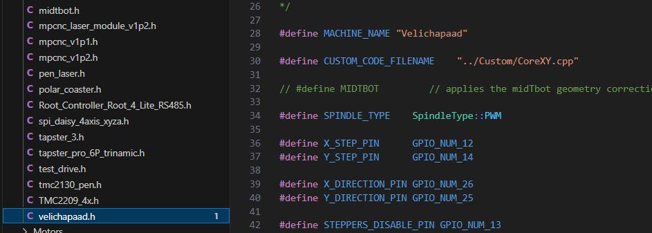
Also we have to edit the velicahapad.h file to make the spindle type to PWM.
You need to include Serial2.h in the Grbl.h file
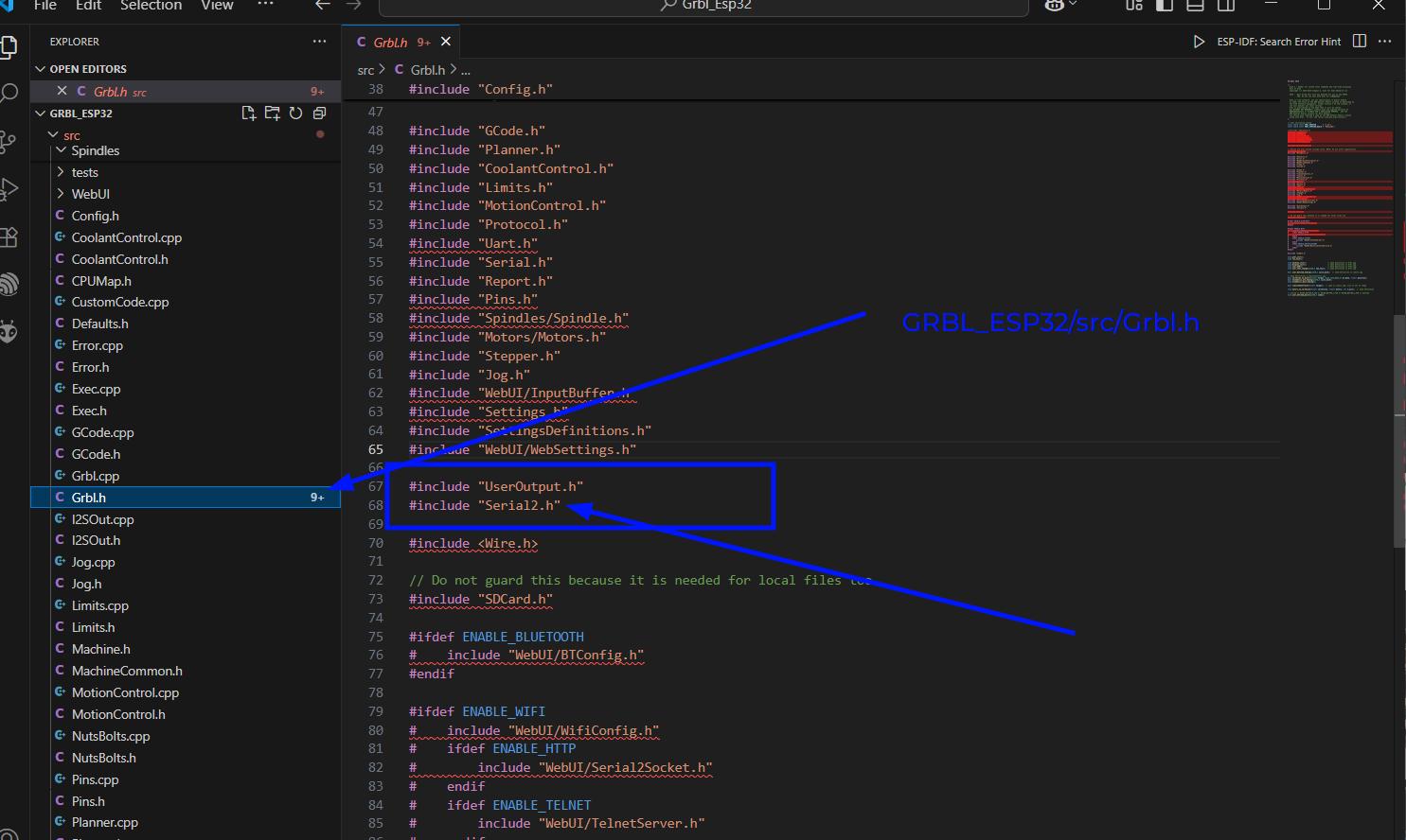
Now the firmware is ready to send serial messages
The firmware programming was mainly done with the help of my friend Vishnu C R and my instructorSaheen. The below github repo is for the final machine firmware.
Velichapad FirmwareUser Interface
The Esp32Grbl comes with a wireless UI interface. The USer Interface is hosted on the ESP32 itself so we can acccess the UI from the IP Address of the ESP32. The ESP32 can be set in either: Station AP or
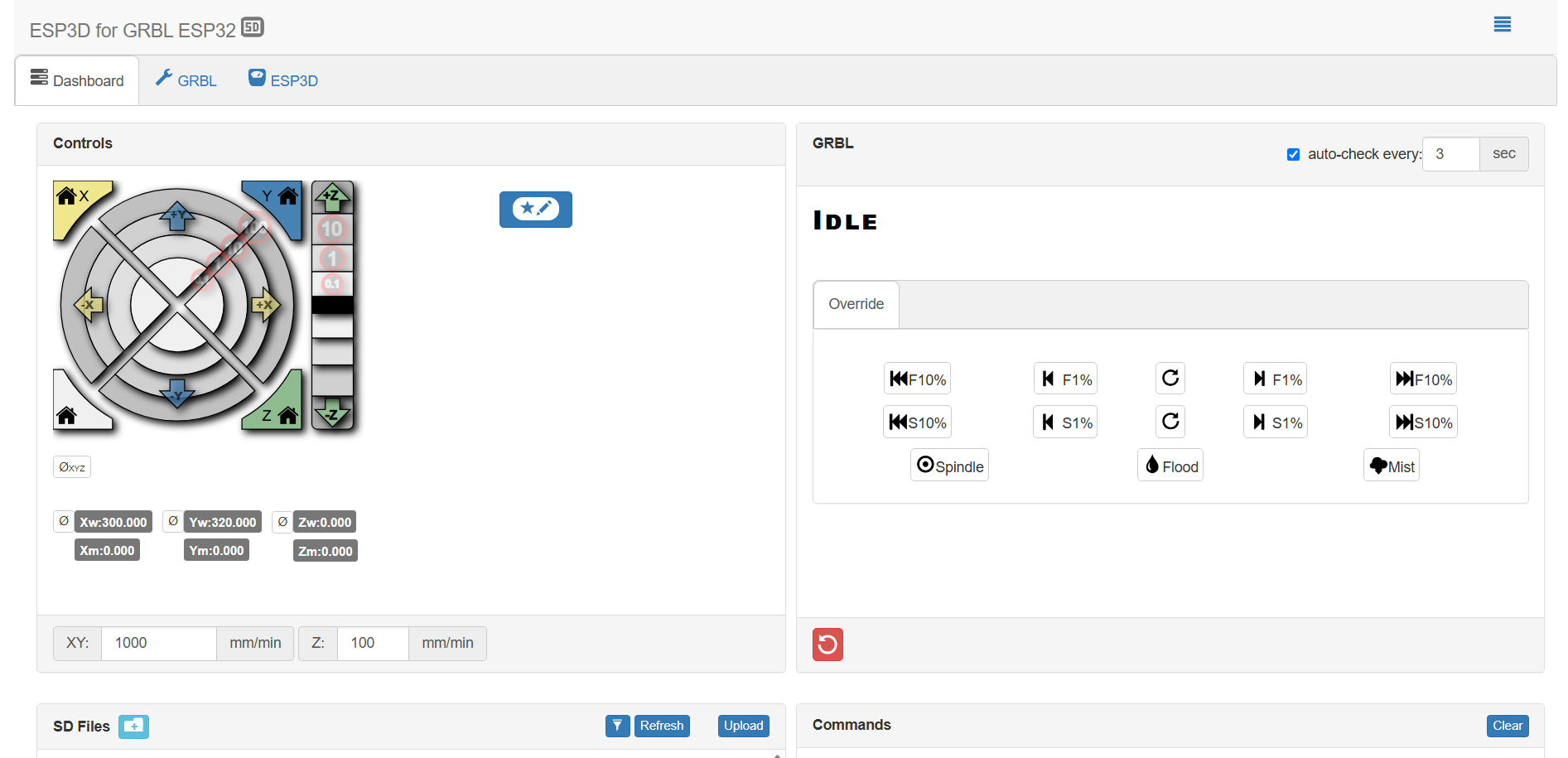
The below given documentation by MakerFr gives a detailed step by step method to initialise GRBL_ESP32 UI. YOu can follow the documentation to setup the UI
GRBL UI Setup DocumentationThe Esp2Grbl UI is a very basic UI with jog controls and allows accessing files from SD and running them.
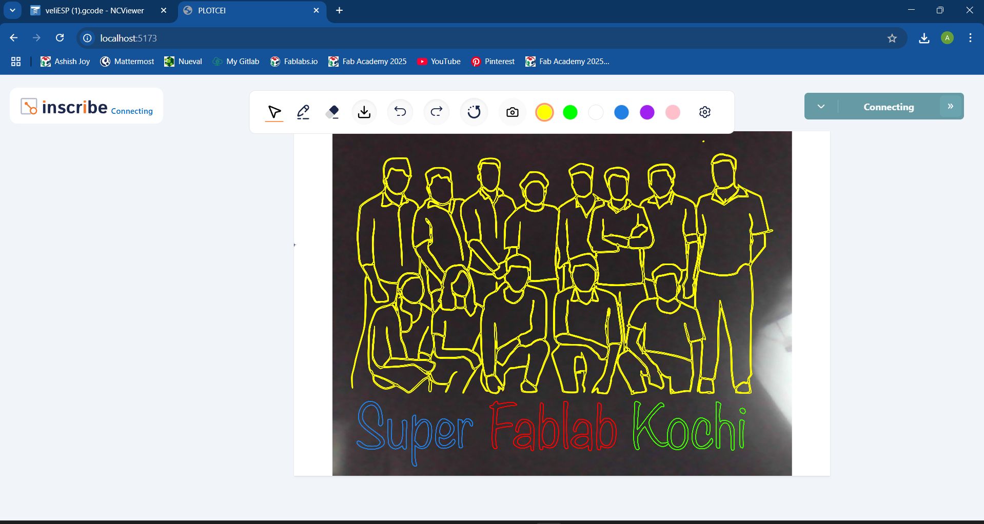
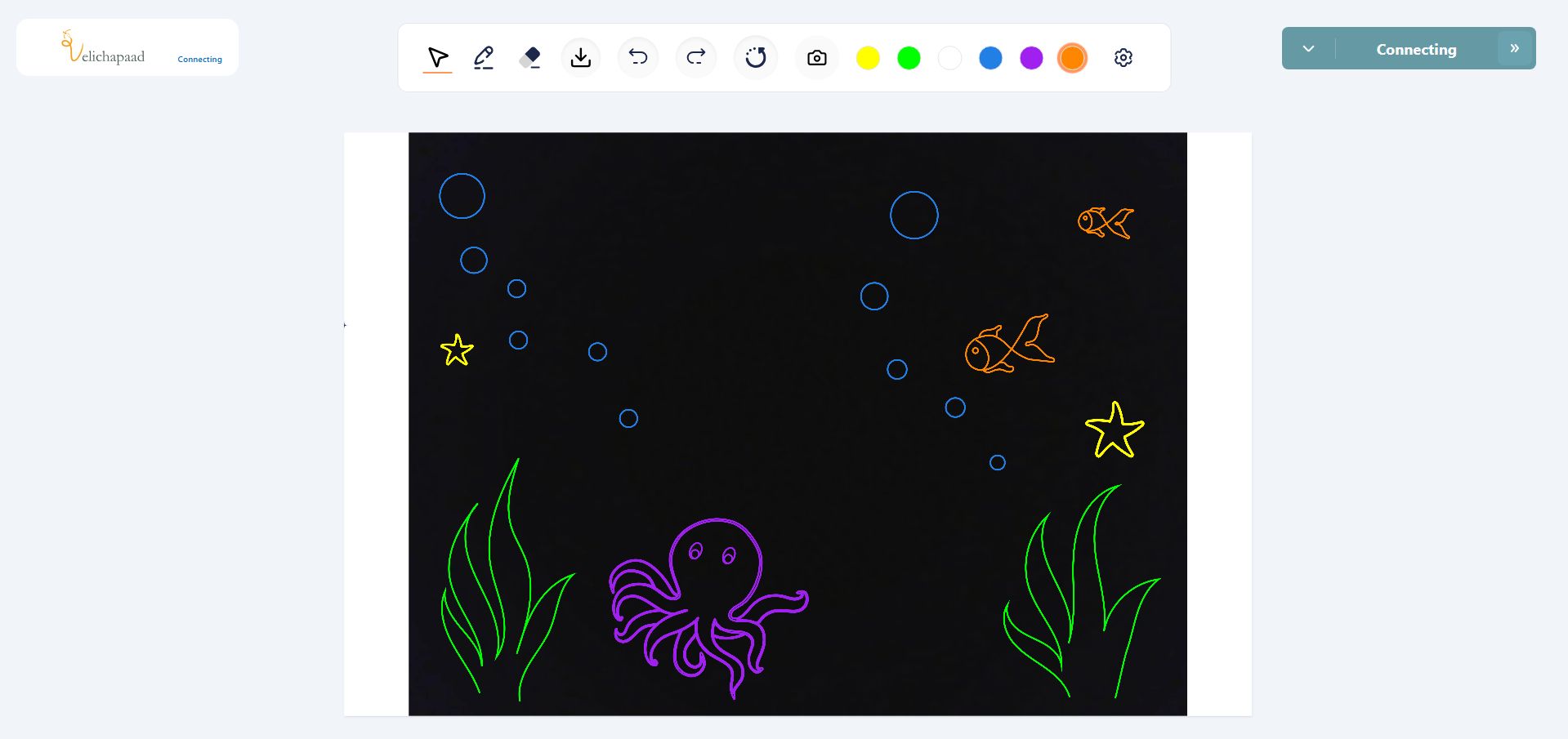
Velichapad UI
In this case we needed a User Interface which would allows us to draw or upload a vector file and send it to the machine. In the basic esp32grbl UI we were sending GCode files which needed to be generated externally. We needed a UI which would help to upload vector image files and convert them into GCode files.
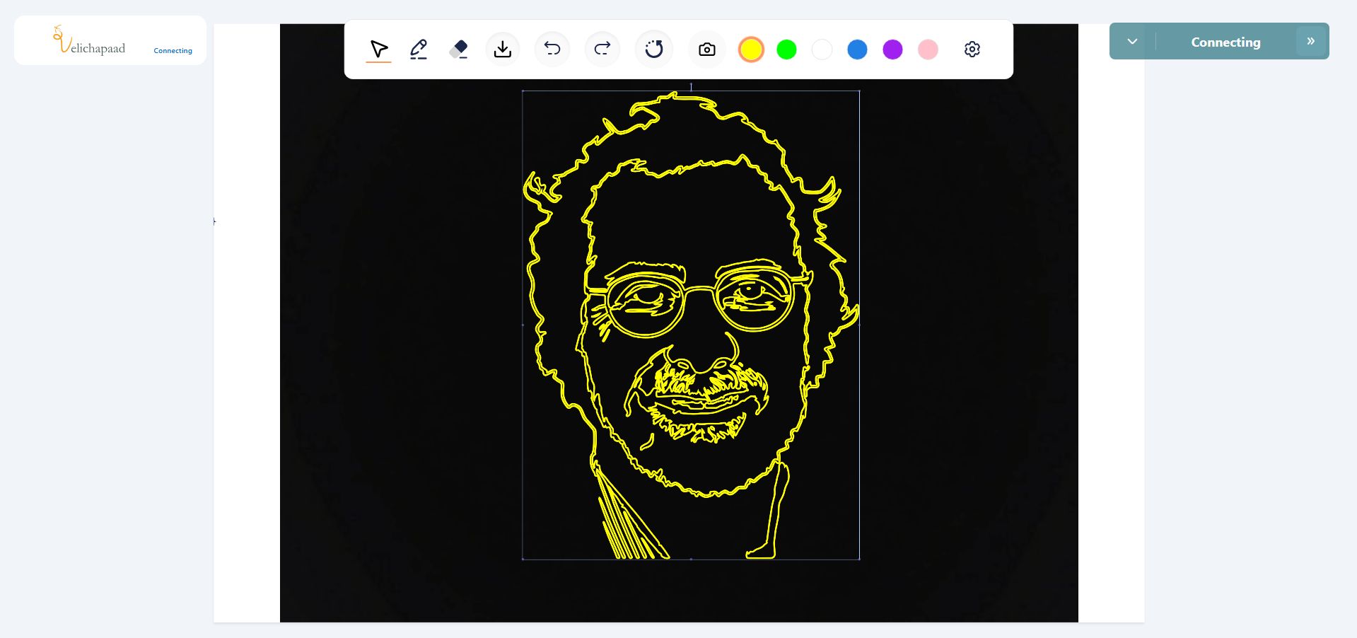
So Midlaj helped us to modify a existing User Inteface that he had already made for another CNC Machine. The only differernce for this machine was that the canvas size was different for this and the code for GCode was M3 and M5 for turning the light ON and OFF. The S parameter along with the M3 code was automatically generated by the UI according to the color selected in the UI. The color parameter was set in binary format for compatibility with the machine.
The below given link is for the github repo for the UI.
Velichapad UI Github RepoAfter downloading the repo, you need to download node.js and run the program using npm run command and it will host a WebUI on the local IP which can be connected by devices on the local network.
Below images show how the UI looks with it's color selection features
Conclusion
For the machine design and mechanical design week, I mostly focused on the electronics, firmware and programming side off the machine. This allowed me to understand the program which makes it possible for machines to run and communicate with its components.
Code Files
You can access my code files from below