Objectives
Group assignment:Measure the power consumption of an output device
Individual assignment: Add an output device to a microcontroller board you've designed, and program it to do something.
Group Assignment
In this week’s assignment, I learned how to measure the power consumption of an output device using a bench power supply. We tested an MG90S servo motor connected to a custom PCB by running a servo sweep program through the Arduino IDE. By setting the power supply to 5V and observing the current draw during operation, we found the servo consumed a maximum of around 0.3A, resulting in a power usage of approximately 1.5W. This helped me understand how to monitor and calculate power consumption in practical setups.
Group assignment pageOutput Devices
An output device is a hardware component that receives data or commands from a microcontroller, processor, or computer and converts them into a form that humans can perceive or use. These devices translate electronically processed information into visual, auditory, or mechanical outputs to interact with the real world. This week I wanted to explore LED and LCD display.
How led works ?
A Light-Emitting Diode (LED) is a semiconductor device that emits light when an electric current passes through it. It consists of a p-n junction made of semiconductor materials, where the n-type region has excess electrons and the p-type region has excess holes. When a voltage is applied, electrons move from the n-type to the p-type region and recombine with holes, releasing energy in the form of photons. The color of the emitted light depends on the band gap energy of the semiconductor material, with different materials producing different wavelengths, such as red, green, blue, or even infrared. LEDs are highly efficient, consuming less power and lasting much longer than traditional incandescent bulbs, making them widely used in displays, lighting, and various electronic applications.
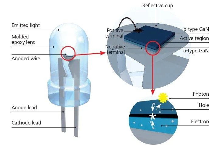 Image
Image
How lcd display works ?
An LCD (Liquid Crystal Display) works by controlling light to create images. It does not produce its own light but instead uses a backlight or a reflective surface. The display has two layers of polarized glass with liquid crystal molecules in between. When no voltage is applied, the liquid crystals allow light to pass through, making the screen appear bright. When voltage is applied, the crystals change their alignment, blocking light and making certain areas appear dark. By controlling which areas let light through, an LCD creates text or images on the screen.
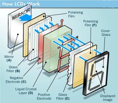 Image
Image
Designing PCB in KiCad
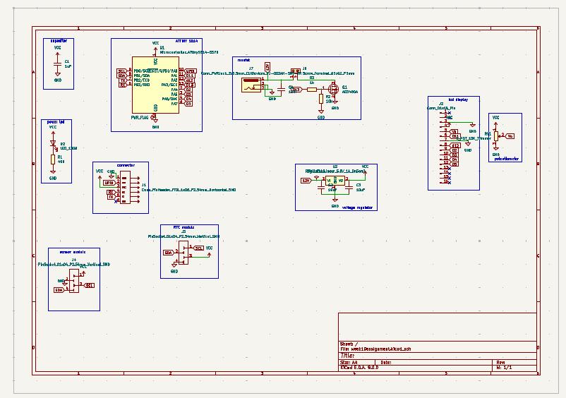
I used ATTINY 1614 microcontroller. As I planned to use a 12 v LED strip, the circuit required a mosfet and voltage regulator.The schematic diagram is shown below.
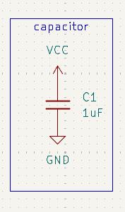
Capacitor
Placing a 1 µF capacitor between the GND and VCC pins of an ATtiny1614 is a standard decoupling practice
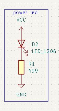
Power led
I added a red power LED in series with a 499 Ω resistor between VCC and GND. This allowed the LED to light up whenever the board was powered, indicating that the circuit was receiving voltage.
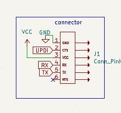
connector
I added a pin header with GND, VCC, RX, TX, and UPDI pins to allow easy connection to the programmer. This made it convenient to power the board and program the ATtiny1614 using the UPDI interface.
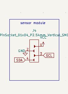
Pin socket for sensor module
I added a pin socket with GND, VCC, SCL, and SDA pins to connect the sensor module. This provided a simple and reliable way to interface the I²C-based sensor with the microcontroller.
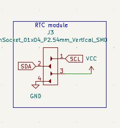
Pin socket for RTC module
The RTC module also had SCL, SDA, VCC, and GND pins for I²C communication.
Working of MOSFET
A MOSFET (Metal-Oxide-Semiconductor Field-Effect Transistor) controls current flow between its source and drain terminals by varying the voltage applied to its gate. It consists of a semiconductor body with an insulating oxide layer separating the gate from the channel. When a voltage is applied to the gate, an electric field modifies the conductivity of the channel, allowing or restricting current flow. MOSFETs operate in two modes: enhancement mode, where no current flows without a gate voltage, and depletion mode, where a conductive channel exists by default and can be turned off with a gate voltage. There are two main types: N-channel MOSFETs, where electrons are the primary charge carriers and current flows when the gate is positively biased, and P-channel MOSFETs, where holes are the charge carriers and current flows when the gate is negatively biased. N-channel MOSFETs are generally preferred for high-speed and high-efficiency applications due to their lower resistance and faster switching characteristics.Here I am using an N-channel MOSFET.
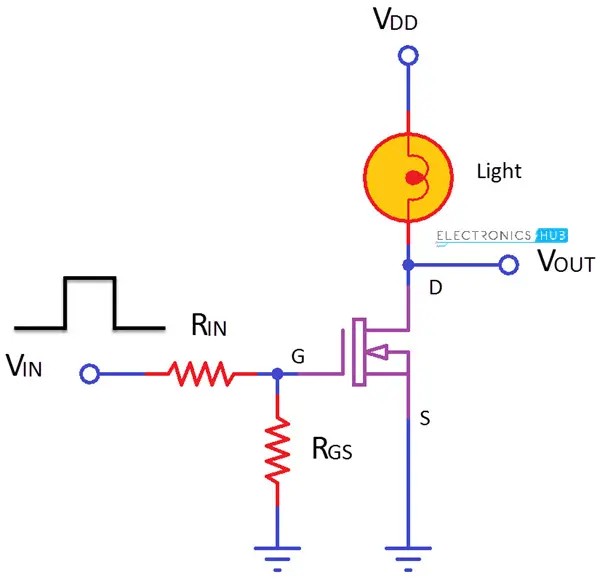 Image
Image
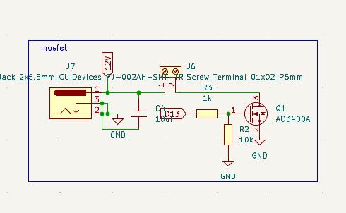
Linear Voltage regulator
A linear voltage regulator keeps the output voltage steady, even if the input voltage or load changes. It does this using a pass transistor, which works like a smart resistor, adjusting how much voltage it drops. A built-in error amplifier constantly checks the output voltage against a fixed reference voltage. If the voltage goes too high or too low, the regulator adjusts the transistor to bring it back to the correct level. Capacitors help smooth things out—an input capacitor cleans up any noise or fluctuations from the power source, while an output capacitor keeps the output stable by reducing small voltage changes. Some regulators, like low-dropout (LDO) regulators, need special capacitors to work properly. Without these capacitors, the regulator might not function correctly or could even become unstable.
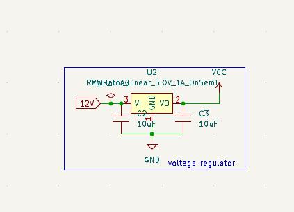
I used connectors to attach sensor module, RTC module, Programmer and LCD display. Before assigning pins to connectors check with your components and design pinsocket accordingly. In the case of LCD display, the pins 15 and 16 were the first two pins. After 15 and 16 pins 1 to 14 were written. So I designed the pin socket as shown below. We need to add a potentiometer for contrast pin in lcd display.
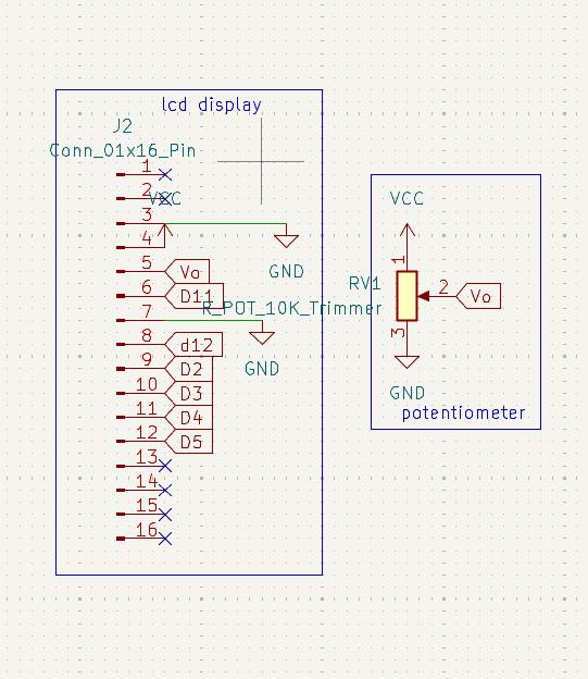
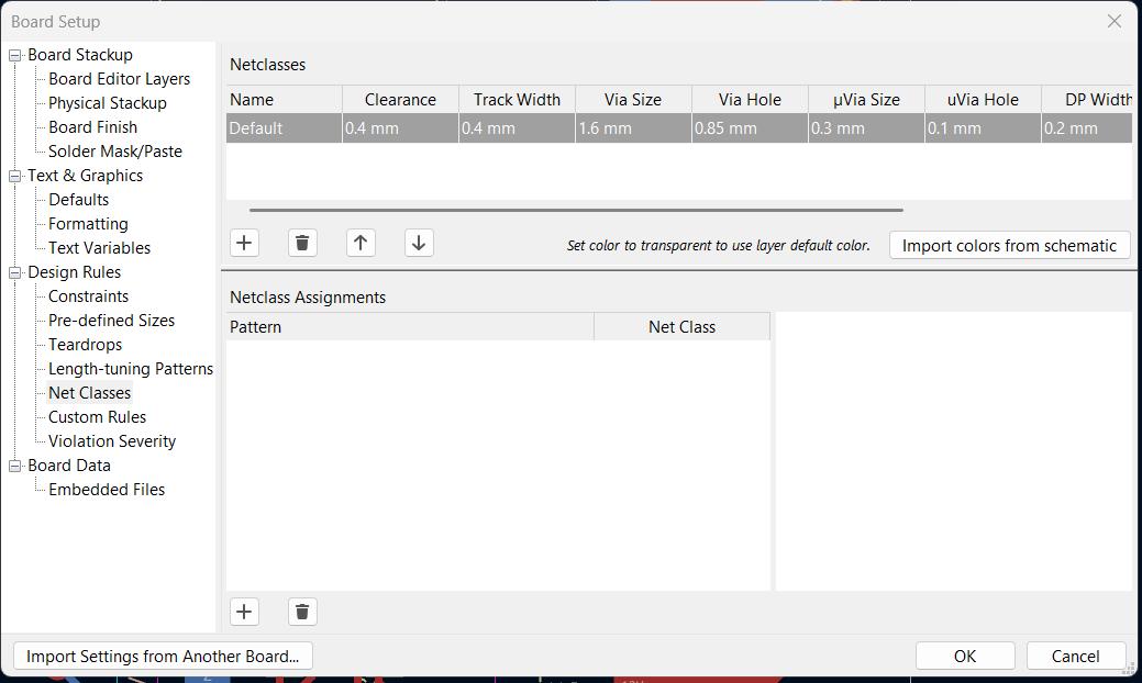
Verify the circuit diagram using ruleschecker tool, correct mistakes if any and open the PCB editor. Click on upload PCB. Now let's track the routes and draw outline for edge cuts.The thing to remember is that we have 12 v tracks in the copper clad board. To facilitate current through track, we need to increase the track width. Track width calculator is avilable in KiCad. I calculated the track width and take 0.8 mm for trackwidth. Rest have a track width of 0.4 mm. Before starting we need to define design rules for the board.
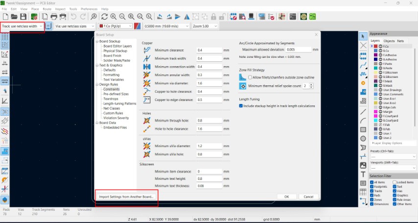
In design rules we have an option to import setting from another board. We can edit values in Track:use netclass width option.
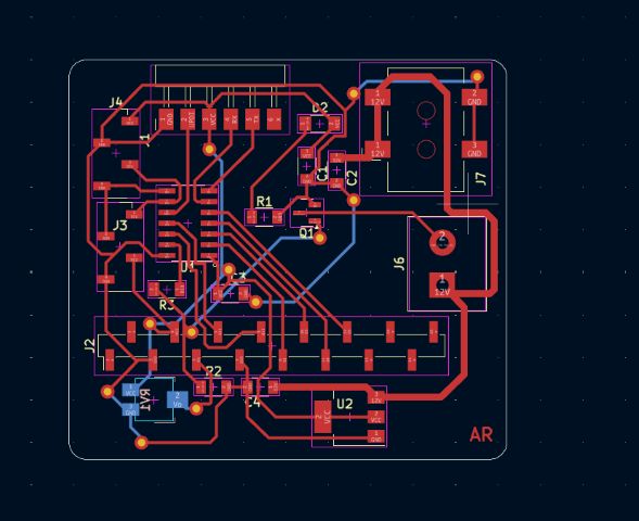
I was making a double layered PCB. To flip to the other side you can use shortcut 'F' and to add vias use 'V'. The vias diameter was .85 mm.
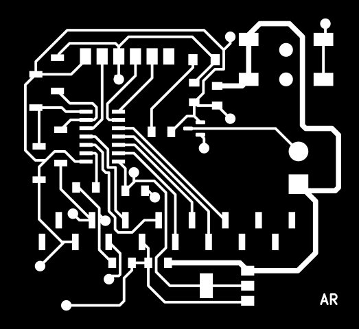
Use ruleschecker to verify the connections. Now we have to change the file to gerber format. Then I uploded the gerber files in gerber2PNG software to convert it to PNG format. For double layer PCB we have five layers to mill.


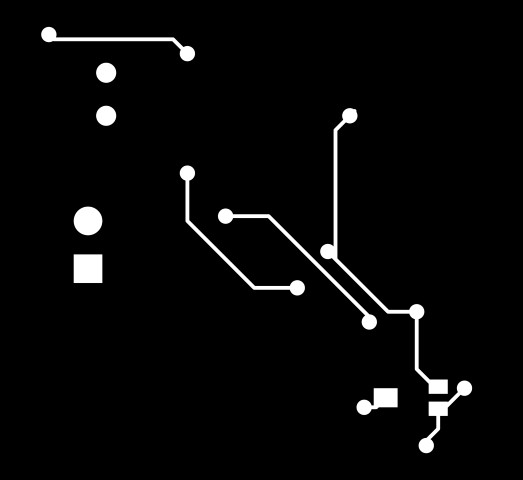

Milling the PCB
As I was milling a double-sided PCB for the first time, my instructor guided me on how to accurately align the two sides.He also showed me how to properly add and connect vias between the top and bottom layers.Using a doublesided tape adhere the double layered copper-clad board in the bed. The Roland Modela MDX-20 machine is used for milling.We need to manually set the zero position(x,y and z-axis).Load the 1/64" engraving bit. Zero the X and Y axes at a corner.Lower the bit slowly until it touches the PCB, then set Z=0.Upload the top trace layer calculate view and send file.
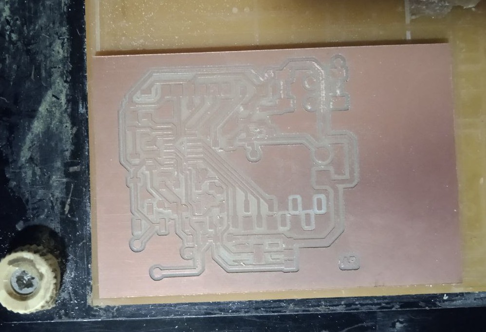
After milling the first layer, carefully replace the bit to 1/32" drill bit for vias, holes and outline cuts.Re-zero only the Z-axis, keeping X and Y unchanged. Resume milling.
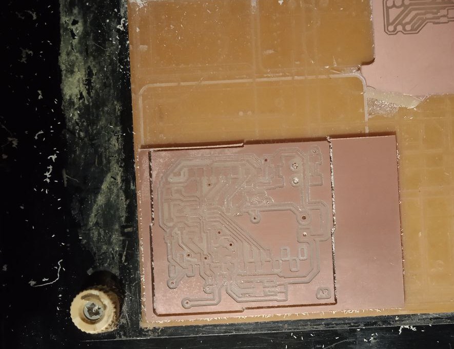
To mill the bottom layer, flip the board along the correct axis. Secure the flipped board using a double-sided tape.
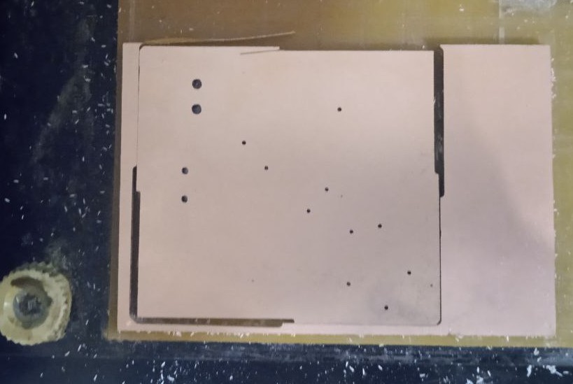
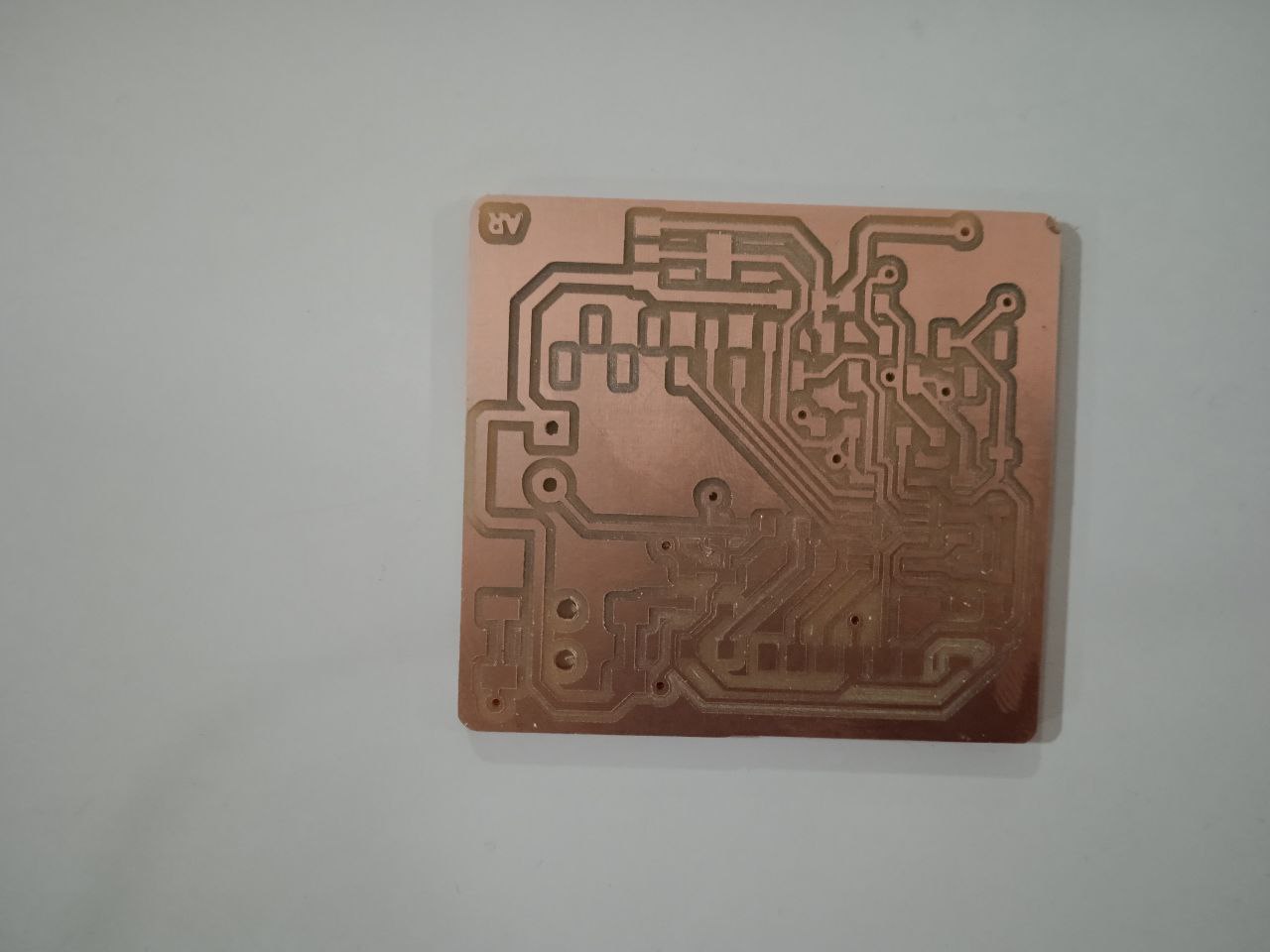
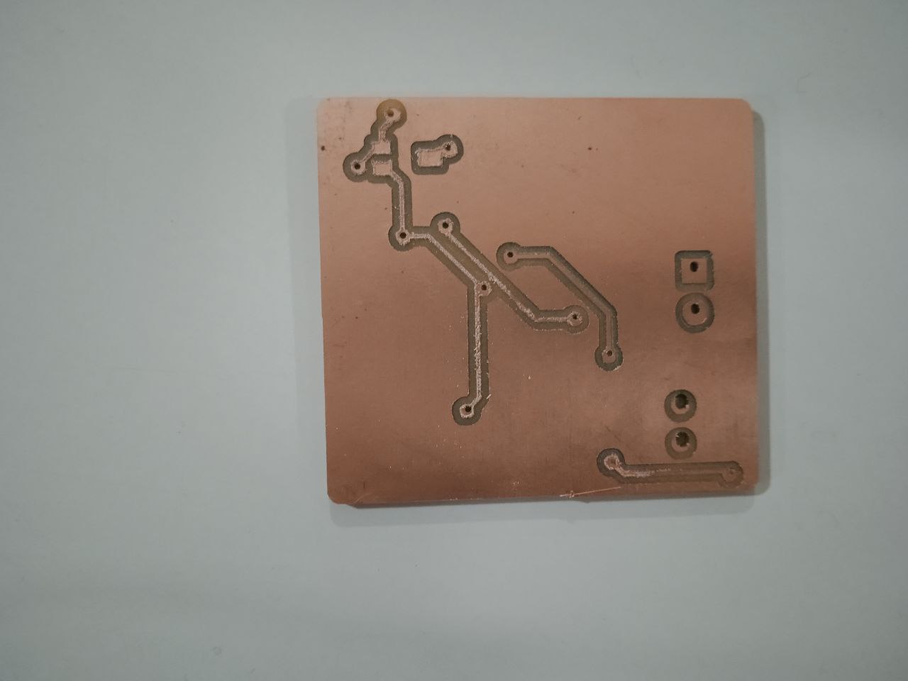
Load the engraving bit and zero the Z-axis again. Run the bottom layer trace milling. Then change the bit.Cut the PCB outline using 1/32" end mill. Here is the final result.
Assembling the components
I requested the components from fabstash and collected it from the inventory. I used ineractive HTML BOM in KiCad to get the list of components. It is also highlights were to place components in the pcb.
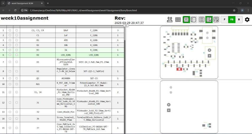
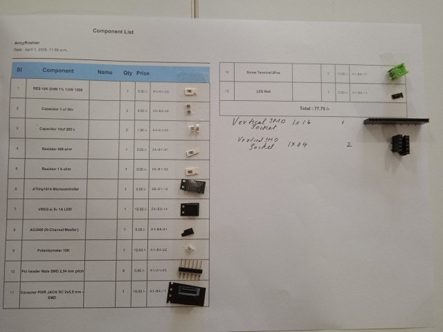
A capacitor value is later changed from 10uF to 100uF.That capacitor needs to be placed in between 12v and GND of powerjack. It serves as a decoupling or bypass capacitor, filtering out high-frequency noise and voltage spikes, and stabilizing the power supply.
First we need to place rivets in the pcb.
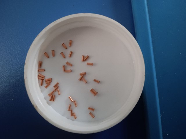
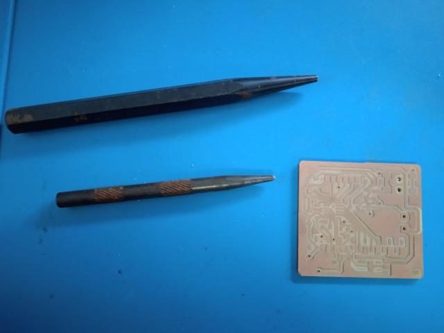
To add rivets to a PCB, first, choose the right size rivets that fit your board’s holes. Drill clean holes in the PCB, making sure they match the rivet size. Insert the rivet into the hole so it sits flat against the board. Then, secure it by pressing or flaring the ends using a small tool or a rivet press. Better practice is to solder the hole with lead, place rivet and heat the lead again so the lead will get placed uniformly. It ensures good connection.
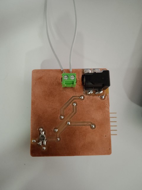
Mistake 1 :While designing the board, I didn't paid attention to the orientation of power jack. While soldering, I realised that the socket is inwards. When I add other components, I will not be able to connect power jack. I discussed the issue with my instructor. As suggested, I placed the jack in bottom layer. By adding rivets, we can make connection with the top and bottom layers.
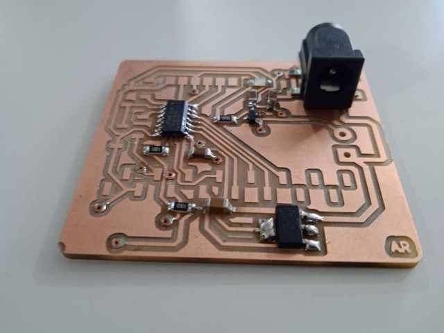
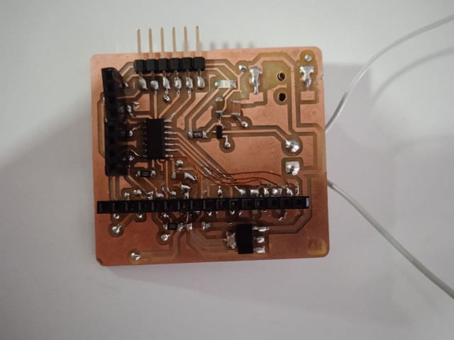
Mistake 2 : I had to change the datapins of lcd from first 4 pins to last four pins.So I needed to make connections using copper wires.
Hero shot
Final PCB
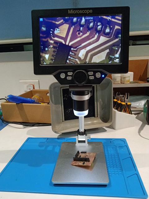
Inspecting the PCB
The first step is microscope inspection, which focuses on visually examining the PCB for physical defects. Check for issues such as poor solder joints, solder bridges, cracked components, or broken traces. Ensure that all components are correctly placed and aligned.
Using digital multimeter electrically test the PCB. Start with a continuity test by setting the multimeter to "beep mode" and placing the probes to Vcc, ground pin, traces and components. Power supply inspection involves applying power to the PCB under controlled conditions. Start with a low voltage and a limited current to prevent damage if a short circuit is present. Gradually increase the voltage to the required level while monitoring the current draw. A normal current draw suggests proper operation, while an unusually high current draw could indicate a shorted component or power rail issue. If a component becomes excessively hot, it may be faulty, and a careful touch can help identify the overheating part. If the board is consuming very little or no current, it may have an open circuit or a missing connection.I tested my 5v and 12v connections and also tested LED strip. After making sure connections are proper, let's program the microcontroller.
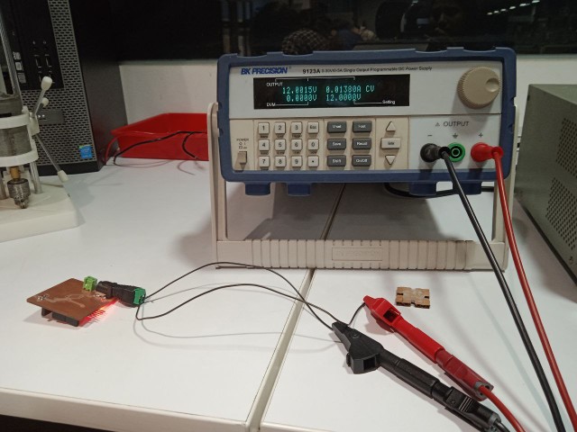
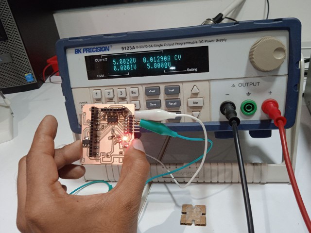
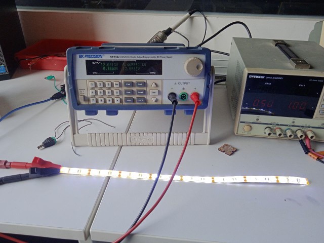
I calculated the power required for the LED strip, P = VI, 12*0.4655 = 5.586 watt
Programmming the PCB
Display time in LCD
Last week I programmed an RTC module to display time in serial monitor. This week I wanted to Display time in LCD. An example program was run to check wheather the LCD is working. Then I programmed to display time. I first tested the example code for the LCD display to ensure it was working correctly.
// include the library code: #include// initialize the library by associating any needed LCD interface pin // with the arduino pin number it is connected to const int rs = 8, en = 9, d4 = 0, d5 = 1, d6 = 2, d7 = 3; LiquidCrystal lcd(rs, en, d4, d5, d6, d7); void setup() { // set up the LCD's number of columns and rows: lcd.begin(16, 2); // Print a message to the LCD. lcd.print("hello, world!"); }
Reference:-Liquid Crystal Displays (LCD) with Arduino
Then I combined it with the RTC module code I had used in input week to display the real-time clock data on the LCD. The code is given below.
#include "Arduino.h"  // Include the core Arduino functions
#include "uRTCLib.h"  // Include the library for the RTC module
#include <LiquidCrystal.h>  // Include the library for the LCD display

// Define the LCD pin connections: rs, en, d4, d5, d6, d7
const int rs = 8, en = 9, d4 = 0, d5 = 1, d6 = 2, d7 = 3;
LiquidCrystal lcd(rs, en, d4, d5, d6, d7);  // Initialize the LCD object with those pins

// Initialize the RTC object with the I2C address of the RTC (0x68 for DS1307/DS3231)
uRTCLib rtc(0x68);

// Define the days of the week as strings for display purposes
char daysOfTheWeek[7][12] = {
  "Sunday", "Monday", "Tuesday", "Wednesday",
  "Thursday", "Friday", "Saturday"
};

void setup() {
  Serial.begin(9600);       // Start the serial communication at 9600 baud
  delay(3000);              // Wait for serial monitor to open (optional but useful for debugging)

  URTCLIB_WIRE.begin();     // Initialize I2C communication for the RTC

  // The following line sets the RTC time manually.
  // You only need to run it once, then comment it out.
  // rtc.set(second, minute, hour, dayOfWeek, dayOfMonth, month, year);
  // Example: rtc.set(0, 19, 14, 4, 2, 4, 25); // April 25, 2024, 14:19:00, Thursday
}

void loop() {
  rtc.refresh();  // Refresh RTC data to read the latest time

  // Print current date and time to Serial Monitor
  Serial.print("Current Date & Time: ");
  Serial.print(rtc.year());
  Serial.print('/');
  Serial.print(rtc.month());
  Serial.print('/');
  Serial.print(rtc.day());

  Serial.print(" (");
  Serial.print(daysOfTheWeek[rtc.dayOfWeek() - 1]);  // Print day of the week
  Serial.print(") ");

  Serial.print(rtc.hour());
  Serial.print(':');
  Serial.print(rtc.minute());
  Serial.print(':');
  Serial.println(rtc.second());

  delay(500);  // Short delay before updating the LCD

  lcd.begin(16, 2);  // Initialize LCD with 16 columns and 2 rows

  // Print the current time to the LCD
  lcd.print(rtc.hour());
  lcd.print(':');
  lcd.print(rtc.minute());
  lcd.print(':');
  lcd.println(rtc.second());

  delay(500);  // Delay before the next update
}
Change light intensity using distance sensor
I used the same code from input week to work with 12v LED strip. I uploaded the program in microcontroller and connected the pcb to 12 V power supply.
// Include required libraries

#include <Wire.h>   // Library for I2C communication
#include <VL53L0X.h>// Library for the VL53L0X Time-of-Flight distance sensor

VL53L0X sensor;              // Create an object for the sensor
int LED = 10;                // Define the digital pin for the LED

void setup() {
    Wire.begin();            // Start I2C communication
    Serial.begin(9600);      // Start serial communication at 9600 baud for debugging

    pinMode(LED, OUTPUT);    // Set the LED pin as output

    if (!sensor.init()) {    // Try to initialize the VL53L0X sensor
        Serial.println("VL53L0X Init Failed!");  // Print error message if it fails
        while (1);           // Stop execution if sensor doesn't initialize
    }

    sensor.setTimeout(500);      // Set timeout duration for sensor operations (500 ms)
    sensor.startContinuous();    // Start continuous distance measurement mode
}

void loop() {
    uint16_t distance = sensor.readRangeContinuousMillimeters();  // Read distance in mm

    if (sensor.timeoutOccurred()) {
        Serial.println("Timeout!");        // Notify if sensor timed out
    } else {
        Serial.print("Distance: ");
        Serial.print(distance / 10);       // Convert mm to cm
        Serial.println(" cm");             // Print distance in cm
    }

    delay(100);                            // Wait 100 milliseconds between readings

    if (distance / 10 < 20) {           // If object is closer than 20 cm
        int brightness = map(distance / 10, 20, 0, 0, 255);  // Map distance to LED brightness
        brightness = constrain(brightness, 0, 255);          // Keep brightness within 0–255
        analogWrite(LED, brightness);                        // Set LED brightness accordingly
    } else {
        analogWrite(LED, 0);         // Turn off LED if object is beyond 20 cm
    }
}
I also noted the variation in power supply current with respect to proximity
Conclusion
This week, I explored output devices by integrating an LED strip and an LCD display into a custom-designed PCB using the ATTINY1614 microcontroller. I designed and fabricated a double-layer PCB in KiCad, incorporating a MOSFET and a voltage regulator to drive a 12V LED strip. During assembly, I encountered and resolved design issues, such as incorrect power jack orientation and LCD pin assignments. I successfully programmed the microcontroller to display real-time data on the LCD and control LED brightness using a distance sensor. Additionally, I measured the power consumption of the LED strip and analyzed its variation with proximity. This assignment strengthened my understanding of PCB design, microcontroller programming, and power management, reinforcing key concepts in embedded systems.