Week 9
Input Devices
This weeks individual assignment was to select an input device and measure some kind of data and a custom bode should be designed to read the data from the input device. The group assignment was to probe an input device's analog levels and digital signals.
Group Assignments
This weeks group assignment is to probe an input device’s analog levels and digital signals. Revisankar had made a board using INMP441 MEMS microphone. We used that board to probe the microphone. Also we tested PS2 Joystick Module Breakout Sensor.
Link : week 9 Group Assignment
MPU6050
The MPU6050 is a 6-axis motion tracking device that combines a 3-axis gyroscope, 3-axis accelerometer, and a Digital Motion Processor (DMP) all in a small 4x4x0.9mm package available as a pin-compatible upgrade from the MPU-3000. With its dedicated I2C sensor bus, the MPU-6050 directly provides complete 6-axis MotionFusion output. The MPU-6050 Motion Processing Unit is the world’s first Motion Processing Unit that integrates a 3-axis gyroscope, 3-axis accelerometer, and a Digital Motion Processor (DMP) hardware accelerator engine into a single small package.

VCC – Supplies power to the sensor (typically 3.3V to 5V, depending on the module).
GND – Ground connection for the circuit.
SCL (Serial Clock Line) – Used for I2C communication, connected to the microcontroller’s SCL pin.
SDA (Serial Data Line) – Transfers data via I2C, connected to the microcontroller’s SDA pin.
XDA (Auxiliary Data Line) – Used to interface with an external sensor but usually left unconnected.
XCL (Auxiliary Clock Line) – Works with XDA for additional sensors but is often unused.
AD0 (Address Select) – Changes the I2C address (LOW: 0x68, HIGH: 0x69); useful for multiple MPU6050s on the same I2C bus.
INT (Interrupt Output) – Sends an interrupt signal to the microcontroller when new data is available.

Image Source :lastminuteengineers.com
How Does a MEMS Accelerometer Work?
A MEMS (Micro-Electro-Mechanical System) accelerometer is a micro-machined structure built on top of a silicon wafer.

Image Source :lastminuteengineers.com
This structure is suspended by polysilicon springs. It allows the structure to deflect when accelerated along the X, Y, and/or Z axes.
As a result of deflection, the capacitance between fixed plates and plates attached to the suspended structure changes. This change in capacitance is proportional to the acceleration along that axis.
The sensor processes this change in capacitance and converts it into an analog output voltage.
How Does a Gyroscope Work?
While accelerometers measure linear acceleration, gyroscopes measure angular rotation. To accomplish this, they measure the force generated by the Coriolis Effect.
Coriolis Effect
The Coriolis Effect states that when a mass (m) moves in a specific direction with a velocity (v) and an external angular rate (Ω) is applied (Red arrow), the Coriolis Effect generates a force (Yellow arrow) that causes the mass to move perpendicularly. The value of this displacement is directly related to the angular rate applied.

Image Source :lastminuteengineers.com
Consider two masses oscillating in opposite directions at a constant frequency. When an angular rate is applied, the Coriolis effect produced by each mass is in opposite directions, resulting in a proportional change in capacitance between the masses. By measuring this change in capacitance, the angular rate can be calculated.

Image Source :lastminuteengineers.com
How Does a MEMS Gyroscope Work?
The MEMS sensor consists of a proof mass (consisting of four parts M1, M2, M3, and M4) that is maintained in a continuous oscillating movement so that it can respond to the coriolis effect. They simultaneously move inward and outward in the horizontal plane.

Image Source :lastminuteengineers.com
When we begin to rotate the structure, the Coriolis force acting on the moving proof mass causes the vibration to change from horizontal to vertical.
There are three modes depending on the axis along which the angular rotation is applied.
Roll Mode:
When an angular rate is applied along the X-axis, M1 and M3 will move up and down out of the plane due to the coriolis effect. This causes a change in the roll angle, hence the name Roll Mode.

Image Source :lastminuteengineers.com
Pitch Mode:
When an angular rate is applied along the Y-axis, M2 and M4 will move up and down out of the plane. This causes a change in the pitch angle, hence the name Pitch Mode.

Image Source :lastminuteengineers.com
Yaw Mode:
When an angular rate is applied along the Z-axis, M2 and M4 will move horizontally in opposite directions. This causes a change in the yaw angle, hence the name Yaw Mode.

Image Source :lastminuteengineers.com
Image Source :lastminuteengineers.com
Whenever the coriolis effect is detected, the constant motion of the driving mass will cause a change in capacitance (∆C) that is detected by the sensing structure and converted into a voltage signal.
For your information, this is what the MEMS structure die of a 3-axis digital gyroscope looks like. Thanks to Adam McCombs for sharing this image of a decapod L3GD20HTR MEMS gyroscope.
Measuring Acceleration
The MPU6050 has an on-chip accelerometer that can measure acceleration over four programmable full scale ranges of ±2g, ±4g, ±8g, and ±16g.

Image Source :lastminuteengineers.com
The MPU6050 is equipped with three 16-bit analog-to-digital converters that simultaneously sample the three axes of movement (along the X, Y, and Z axes).
Measuring Rotation
The MPU6050 has an on-chip gyroscope that can measure angular rotation over four programmable full scale ranges of ±250°/s, ±500°/s, ±1000°/s, and ±2000°/s.

Image Source :lastminuteengineers.com
The MPU6050 is equipped with three more 16-bit analog-to-digital converters that simultaneously sample the three axes of rotation (along the X, Y, and Z axes). The sampling rate can be adjusted from 3.9 to 8000 samples per second
The documentation was obtained from lastminuteengineers.com
Board designed
For this weeks assignment i wanted to make a small and intreating PCB that would be fun to play for this iMy idea was to make led board connected to an IMU that glows depending on the angle at which the board is held. I wanted 8 LEDs that should be placed at a 45 deg angle and using the data From the IMU the and finding the inclination to glow LEDs, For this i wanted a small microcontroller that has enough pins to control the LEDs do IChose chose the ATtiny3216 and using the and I made the Schematic I used the referred the data sheet ATtiny3216 and the lastminuteengineers.com for getting info about the IMU
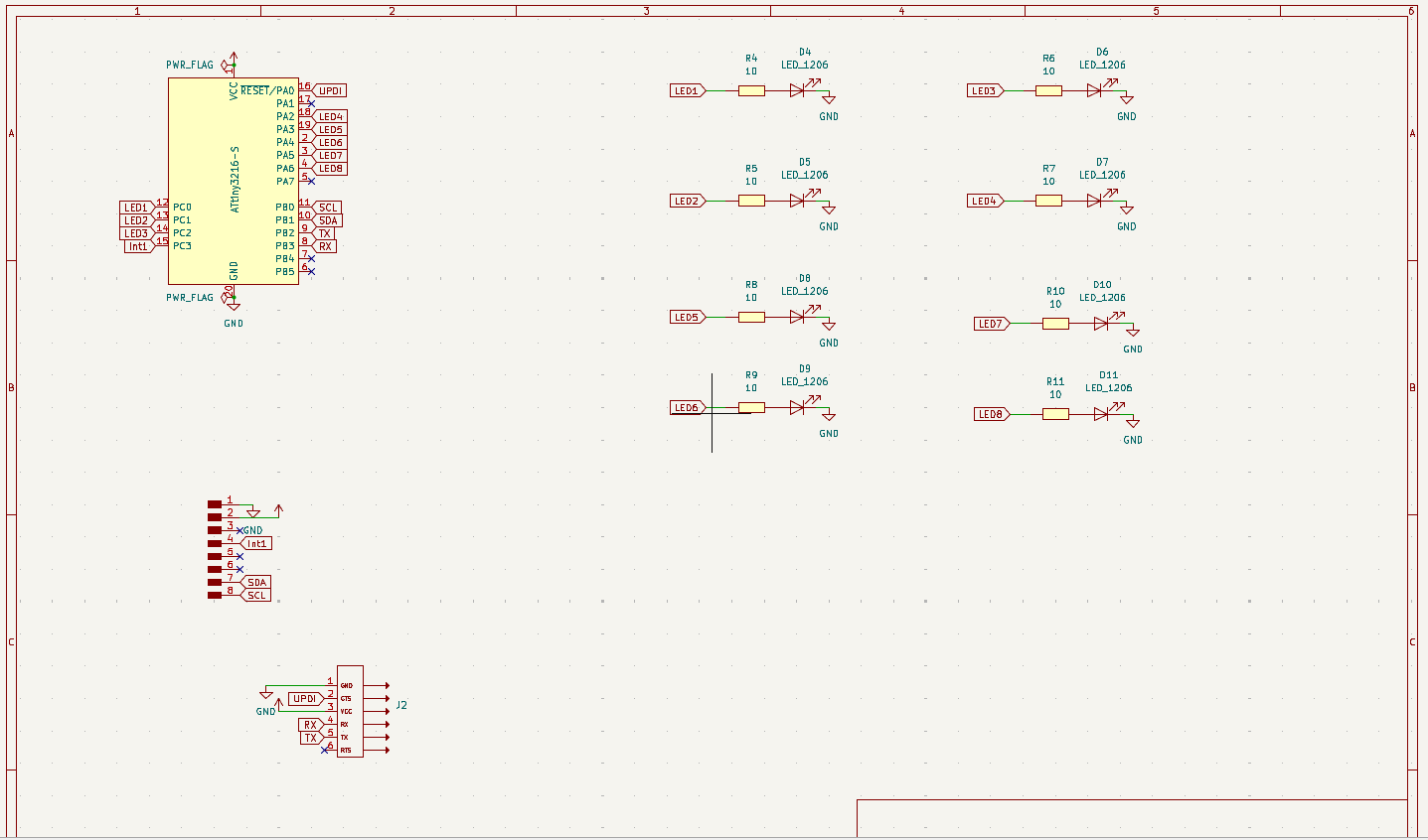
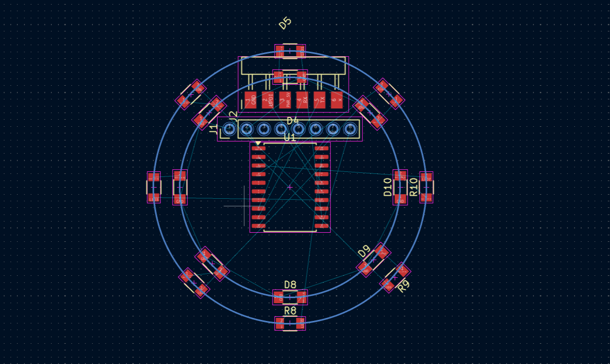
I hade used Kicad to design the pcb and i wanted it to be round Also I had to used a double sided pcb to make it compact and aesthetic.
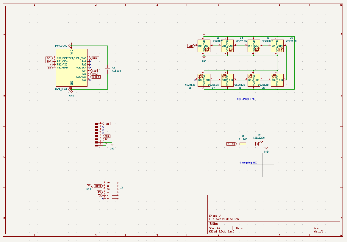
When I shared my Idea with my instructor he suggested to use Neo Pixel LEDS to make the routing easier and it would be fun to play with it so i used Neo Pixel LEDS and then i made the schematic and i changed the Micro controller to ATtiny1614 since I wanted only one pin for the Neo Pixel LEDs and the IMU is using I2C
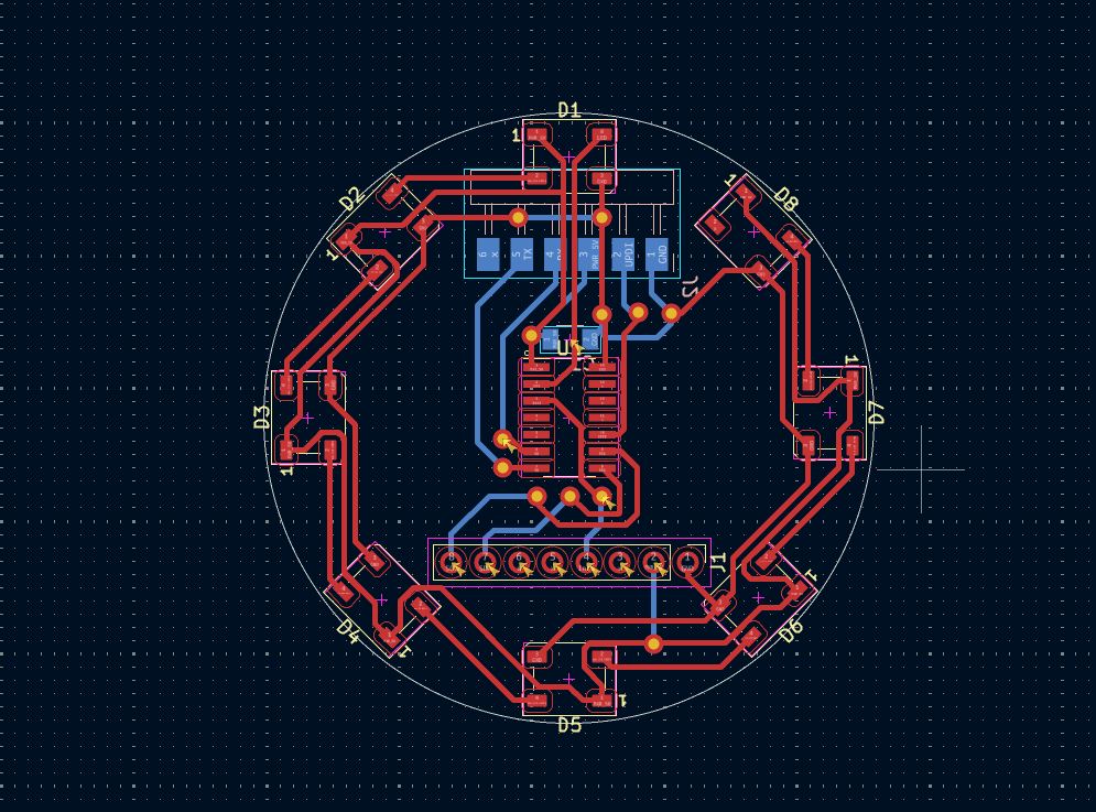
Then i made the circuit i tried to make it symmetric, compact and aesthetic
The only faces some issues here i hade to manually change the dimension of each via in the schematic separately.
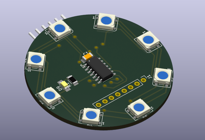
And this is the final board in 3D
Milling
I used the Modela to mill the PCB and I used the 1/64 end mill to mill the PCB and I used the 1/32 end mill to drill the holes since it is a two sided PCB I had to follow some extra steps It was easy to follow since i was using gerber2png and I followed the documentation from the wiki for milling the double sided PCB

I had faced an issue of the tracks peeling off then i hade to mill again and then accidentally wile placing the board for second side I placed the board on the orientation so i Had to mill again to get a satisfactory result.

This is the final result i received and it was looking good

THe next step was adding the rivets on to the board for this i am using a .8mm rivet first inserted all the rivets in the specific
Then using the center punch to flatten the rivets on the other side


Soldering
For soldering first i collected all the components from inventory and arranged all the components in the BOM for ease of soldering.

Then i started soldering the components on the board first i soldered the resistors and the capacitors and then the IC and then the LEDs and then the headers and then the rivets
Here i had to solder all the rivets since it as not properly conducting
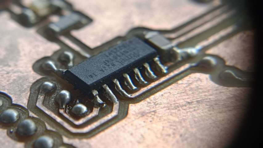
Soldering the neo pixel LEDs were very hard because the pads were very small so to Make it get properly soldered I had to sand the pin of the LED then soldered it, since the Neo pixel LEDs have to be solder at the bottom it was easily getting disconnected even with a small force so i had to solder it multiple times and when the LED was getting heated it was getting damage
And then I soldered the IMU in a wrong way and the IMU was getting heated due to some shot circuits.
Then I had to remove the IMU and then solder it again and then I had to solder the IMU in a different way and the i found it by testing with a multimeter since the voltage that i was getting was not 5v Then i sorted it out.
After correcting all the issues the board was working


Programming
Fist install megaTinyCore follow the steps from the documentation mentioned below
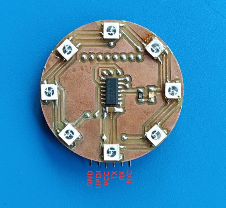
This is the pin out from my board this is used for programming as well as powering
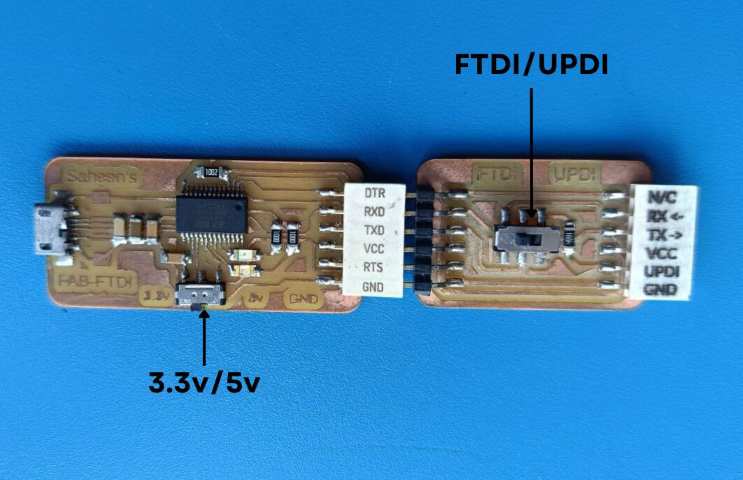
For programming the board I used the Arduino IDE an external Programmer
Flashing Bootloader
Step 1: Install the necessary core for ATtiny1614
Open Arduino IDE.
Go to File → Preferences.
In the Additional Board Manager URLs field, add:
http://drazzy.com/package_drazzy.com_index.json
Click OK.
Open Tools → Board → Board Manager.
Search for megaTinyCore and install it.
Step 2: Connect the UPDI Programmer
Use an FTDI Adapter (or similar) as UPDI Programmer:
Simply connect UPDI → UPDI, GND → GND, VCC → VCC.
Step 3: Configure Arduino IDE
Select Board:
Go to Tools → Board → megaTinyCore
Select ATtiny1614.
Set Programmer:
Go to Tools → Programmer
Choose serialUPDI - SLOW 57600 baud
Other Settings:
Chip: ATtiny1614
Clock: 16MHz
UPDI I/O Mode: UPDI
Step 4: Burn the Bootloader
Click Tools → Burn Bootloader.
Wait for the process to complete.
If successful, you can now upload sketches directly via UPDI.
Test 1
Here using the Adafruit MPU6050 library to interface with the MPU6050 sensor, I am reading acceleration data and determining movement direction.
In the setup() function, the code initializes the serial monitor at a baud rate of 115200 and attempts to connect to the MPU6050 sensor. If the connection fails, it prints an error message and enters an infinite loop. The accelerometer and gyroscope ranges are set to ±16g and ±500°/s, respectively, with a filter bandwidth of 10Hz to smooth out noise.
In the loop(), the code retrieves sensor data, storing it in a (acceleration), g (gyro), and temp (temperature) event structures. It extracts the X and Y acceleration values and prints movement directions based on their values:
-
If accelX < 0, it prints "B" (backward), and if accelX > 0, it prints "F" (forward).
-
If accelY < 0, it appends " R" (right), and if accelY > 0, it appends " L" (left).
-
The delay(800) ensures readings are taken at a slower interval (800ms).
The above explanation of the code was generated by chat GPT
Prompt : Give the brief explanation of the code i give in paragraph
        // Include the required libraries for MPU6050 and I2C communication
#include
#include
#include

// Create an instance of the MPU6050 sensor
Adafruit_MPU6050 mpu;

void setup() {
  Serial.begin(115200);  // Initialize serial communication for debugging

  // Attempt to initialize the MPU6050
  if (!mpu.begin()) {
    Serial.println("Failed to find MPU6050 chip");
    while (1) {
      delay(500);  // If initialization fails, stay here
    }
  }

  // Configure accelerometer and gyroscope settings
  mpu.setAccelerometerRange(MPU6050_RANGE_16_G);     // Set accelerometer sensitivity to ±16G
  mpu.setGyroRange(MPU6050_RANGE_500_DEG);           // Set gyroscope sensitivity to ±500°/s
  mpu.setFilterBandwidth(MPU6050_BAND_10_HZ);        // Set filter bandwidth for noise reduction
}

void loop() {
  // Declare sensor event objects for accelerometer, gyroscope, and temperature
  sensors_event_t a, g, temp;

  // Read data from MPU6050 sensor
  mpu.getEvent(&a, &g, &temp);

  // Get acceleration values along X and Y axes
  float accelX = a.acceleration.x;
  float accelY = a.acceleration.y;

  // Determine forward/backward motion based on X-axis acceleration
  if (accelX < 0) {
    Serial.println("B");  // Backward
  } else if (accelX > 0) {
    Serial.println("F");  // Forward
  }

  // Determine right/left motion based on Y-axis acceleration
  if (accelY < 0) {
    Serial.print(" R");  // Right
  } else if (accelY > 0) {
    Serial.print(" L");  // Left
  }

  // Wait before next reading
  delay(800);
}
Test 2
Here this code works similar to the pervious but it uses the Serial plotter to plot the data for easier observation
I got this code from RandomNerdTutorials.comrefer this website for more information
  // Basic demo for accelerometer readings from Adafruit MPU6050

  // Arduino Guide: https://RandomNerdTutorials.com/arduino-mpu-6050-accelerometer-gyroscope/

  #include <Adafruit_MPU6050.h>
  #include <Adafruit_Sensor.h>
  #include <Wire.h>

  Adafruit_MPU6050 mpu;

  void setup(void) {
    Serial.begin(115200);
    while (!Serial) {
      delay(10);
    }

    // Try to initialize!
    if (!mpu.begin()) {
      Serial.println("Failed to find MPU6050 chip");
      while (1) {
        delay(10);
      }
    }

    mpu.setAccelerometerRange(MPU6050_RANGE_16_G);
    mpu.setGyroRange(MPU6050_RANGE_250_DEG);
    mpu.setFilterBandwidth(MPU6050_BAND_21_HZ);
    Serial.println("");
    delay(100);
  }

  void loop() {

    /* Get new sensor events with the readings */
    sensors_event_t a, g, temp;
    mpu.getEvent(&a, &g, &temp);

    /* Print out the values */
    Serial.print(a.acceleration.x);
    Serial.print(",");
    Serial.print(a.acceleration.y);
    Serial.print(",");
    Serial.print(a.acceleration.z);
    Serial.print(", ");
    Serial.print(g.gyro.x);
    Serial.print(",");
    Serial.print(g.gyro.y);
    Serial.print(",");
    Serial.print(g.gyro.z);
    Serial.println("");

    delay(10);
  }
AI was used to generate the comments for the code
Test 3
Here I am using the Adafruit MPU6050 library to interface with the MPU6050 sensor, I am reading acceleration data and detecting single and double taps. The code initializes the sensor and sets the accelerometer range to ±8g and the gyroscope range to ±500°/s. It also configures the filter bandwidth to 21Hz for noise reduction.
          // Include necessary libraries for MPU6050 and I2C communication
#include
#include
#include

// Create an instance of the MPU6050 class
Adafruit_MPU6050 mpu;

// Variables for detecting taps
unsigned long lastTapTime = 0;      // Time of the last detected tap
bool firstTapDetected = false;      // Flag for first tap detection
const float tapThreshold = 15.0;    // Acceleration threshold to detect a tap (adjustable)
const int doubleTapTime = 300;      // Max time between taps (in ms) to consider it a double tap

void setup() {
  Serial.begin(115200);  // Start serial communication for debugging

  // Attempt to initialize the MPU6050 sensor
  if (!mpu.begin()) {
    Serial.println("Failed to find MPU6050 chip");
    while (1) {
      delay(10);  // Stay here if MPU initialization fails
    }
  }

  // Set accelerometer sensitivity to ±8G
  mpu.setAccelerometerRange(MPU6050_RANGE_8_G);

  // Set gyroscope sensitivity to ±500 degrees/sec (not used in this sketch, but initialized)
  mpu.setGyroRange(MPU6050_RANGE_500_DEG);

  // Set digital low pass filter bandwidth to 21Hz (helps reduce noise)
  mpu.setFilterBandwidth(MPU6050_BAND_21_HZ);

  Serial.println("MPU6050 connection successful.");
}

void loop() {
  // Create sensor event objects
  sensors_event_t a, g, temp;

  // Get sensor data for accelerometer, gyroscope, and temperature
  mpu.getEvent(&a, &g, &temp);

  // Calculate total acceleration magnitude using Pythagorean theorem
  float acceleration = sqrt(
    a.acceleration.x * a.acceleration.x +
    a.acceleration.y * a.acceleration.y +
    a.acceleration.z * a.acceleration.z
  );

  // Check if acceleration exceeds the tap detection threshold
  if (acceleration > tapThreshold) {
    unsigned long currentTime = millis();  // Get current time in milliseconds

    // Check if this is a second tap within the double tap time window
    if (firstTapDetected && (currentTime - lastTapTime < doubleTapTime)) {
      Serial.println("Double Tap Detected!");
      firstTapDetected = false;  // Reset for next detection
    } else {
      Serial.println("Single Tap Detected!");
      firstTapDetected = true;
      lastTapTime = currentTime;
    }
  }

  delay(10);  // Small delay to reduce false positives
}
AI was used to generate the comments for the code
Neo Pixel LED Test
Here I am using the Adafruit NeoPixel library to control a strip of NeoPixel LEDs. The code initializes the strip with the number of LEDs and the pin connected to the strip. The colorWipe() function is used to fill the strip with a specified color and delay between each LED. The loop() function calls the colorWipe() function with different colors (red, green, and blue) to create a color wipe effect.
The code was generated by chat GPT
Prompt : Generate code to control a NeoPixel strip of 8 LEDs using the Adafruit NeoPixel library.
    #include <Adafruit_NeoPixel.h>

      #define LED_PIN 0      // Pin connected to the NeoPixel strip
      #define NUM_LEDS 8    // Change this to the number of LEDs you have

      Adafruit_NeoPixel strip(NUM_LEDS, LED_PIN, NEO_GRB + NEO_KHZ800);

      void setup() {
        strip.begin();      // Initialize NeoPixel strip
        strip.show();       // Turn off all LEDs initially
      }

      void loop() {
        colorWipe(strip.Color(255, 0, 0), 50);  // Red
        colorWipe(strip.Color(0, 255, 0), 50);  // Green
        colorWipe(strip.Color(0, 0, 255), 50);  // Blue
      }


      void colorWipe(uint32_t color, int wait) {
        for(int i = 0; i < strip.numPixels(); i++) {
          strip.setPixelColor(i, color);
          strip.show();
          delay(wait);
        }
      }
AI was used to generate the comments for the code
Left and Right
Here I am using the Adafruit MPU6050 library to interface with the MPU6050 sensor, I am reading acceleration data and determining movement direction and I made the code on the simple logic ,
This code reads Y-axis acceleration from the MPU6050 sensor and controls an 8-pixel NeoPixel LED strip based on tilt. It initializes the MPU6050 to measure motion and configures the NeoPixel LEDs, ensuring they start in an off state.
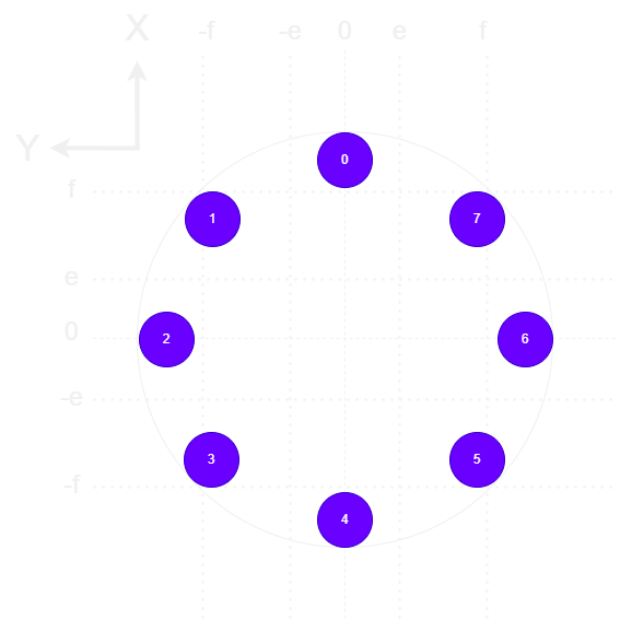
Inside the loop, the code retrieves acceleration data and checks the Y-axis value. Depending on its magnitude, specific LEDs light up in red to represent tilt direction. Small positive values (0 to 1g) activate LEDs 0 & 4, moderate values (1 to 3g) light up LEDs 1 & 3, and high values (>3g) turn on LED 2. Similarly, negative values follow a mirrored pattern, with LEDs 5 & 7 lighting up for moderate negative acceleration and LED 6 for high negative values.
A function (glowLEDs) manages LED control by receiving an
array of LED indexes and a color, clearing previous LEDs, and setting new
ones accordingly. If no significant tilt is detected, the LEDs turn off to maintain a clear
display. The 100ms delay ensures smooth updates while avoiding rapid flickering.
    #include <Adafruit_MPU6050.h>
      #include <Adafruit_Sensor.h>
      #include <Wire.h>
      #include <Adafruit_NeoPixel.h>

      #define PIN 6
      #define NUMPIXELS 8

      Adafruit_NeoPixel pixels(NUMPIXELS, PIN, NEO_GRB + NEO_KHZ800);
      Adafruit_MPU6050 mpu;

      void setup() {
        Serial.begin(115200);

        if (!mpu.begin()) {
          Serial.println("Failed to find MPU6050 chip");
          while (1) {
            delay(500);
          }
        }

        mpu.setAccelerometerRange(MPU6050_RANGE_16_G);
        mpu.setGyroRange(MPU6050_RANGE_500_DEG);
        mpu.setFilterBandwidth(MPU6050_BAND_10_HZ);

        pixels.begin();
        pixels.clear();
        pixels.show();
      }

      void loop() {
        sensors_event_t a, g, temp;
        mpu.getEvent(&a, &g, &temp);

        float accelY = a.acceleration.y;

        Serial.print("Acceleration Y: ");
        Serial.println(accelY);

        if (accelY > 0) {
          int leds1[] = {0, 1, 2, 3, 4};
          glowLEDs(leds1, 5, pixels.Color(255, 0, 0));
        }
        else if (accelY < 0) {
          int leds2[] = {4, 5, 6, 7, 0};  // LEDs 5, 8, 1
          glowLEDs(leds2, 5, pixels.Color(0, 0, 255));
        }
        else {
          pixels.clear();
          pixels.show();
        }

        delay(100);
      }

      // Function to glow selected LEDs using an array
      void glowLEDs(int leds[], int size, uint32_t color) {
        pixels.clear();
        for (int i = 0; i < size; i++) {
          pixels.setPixelColor(leds[i], color);
        }
        pixels.show();
      }
AI was used to generate the comments for the code
Anti Gravity
This code reads Y-axis acceleration from the MPU6050 sensor and controls an 8-pixel NeoPixel LED strip accordingly. It first initializes the MPU6050 and sets its accelerometer range to ±16g, gyroscope range to ±500°/s, and filter bandwidth to 10Hz for noise reduction. The NeoPixel LEDs are also initialized and cleared to ensure they start in an off state.
Inside the loop, the code reads acceleration data and checks the Y-axis value. Based on the tilt, specific LEDs light up in red to visually indicate motion. Lower acceleration values (0 to ±1g) activate LEDs 0 & 4, moderate values (1 to ±3g) light up LEDs 1, 3, 5, and 7, and high values (>3g or < -3g) turn on LEDs 2 & 6. If no significant movement is detected, the LEDs turn off.
A helper function, glowLEDs(), manages LED control by receiving an array of LED indexes and a color, clearing previous LEDs, and setting new ones accordingly. The 100ms delay prevents rapid flickering and ensures smooth updates.
The above explanation of the code was generated by chat GPT
Prompt : Give the brief explanation of the code i give in paragraph
     // Include required libraries for MPU6050 and NeoPixel
#include
#include
#include
#include

// Define NeoPixel pin and number of LEDs
#define PIN 0             // Pin connected to the NeoPixel strip
#define NUMPIXELS 8       // Total number of LEDs in the strip

// Create NeoPixel and MPU6050 objects
Adafruit_NeoPixel pixels(NUMPIXELS, PIN, NEO_GRB + NEO_KHZ800);
Adafruit_MPU6050 mpu;

void setup() {
  Serial.begin(115200);  // Initialize serial communication

  // Initialize MPU6050
  if (!mpu.begin()) {
    Serial.println("Failed to find MPU6050 chip");
    while (1) {
      delay(500);  // Loop forever if MPU not found
    }
  }

  // Set desired sensitivity and filter bandwidth
  mpu.setAccelerometerRange(MPU6050_RANGE_16_G);
  mpu.setGyroRange(MPU6050_RANGE_500_DEG);
  mpu.setFilterBandwidth(MPU6050_BAND_10_HZ);

  // Initialize NeoPixel strip
  pixels.begin();
  pixels.clear();
  pixels.show();
}

void loop() {
  // Declare sensor event variables
  sensors_event_t a, g, temp;

  // Read sensor values
  mpu.getEvent(&a, &g, &temp);

  // Get Y-axis acceleration value
  float accelY = a.acceleration.y;

  Serial.print("Acceleration Y: ");
  Serial.println(accelY);

  // Check Y acceleration range and display corresponding LED pattern

  if (accelY > 0 && accelY <= 1) {
    // Slight positive tilt - glow LEDs 0 and 4
    int leds1[] = {0, 4};
    glowLEDs(leds1, 2, pixels.Color(255, 0, 0));  // Red
  }
  else if (accelY > 1 && accelY <= 3) {
    // Moderate tilt - glow LEDs 1 and 3
    int leds1[] = {1, 3};
    glowLEDs(leds1, 2, pixels.Color(255, 0, 0));  // Red
  }
  else if (accelY > 3) {
    // Strong tilt - glow LED 2
    int leds1[] = {2};
    glowLEDs(leds1, 1, pixels.Color(255, 0, 0));  // Red
  }
  else if (accelY < 0 && accelY >= -1) {
    // Slight negative tilt - glow LEDs 0 and 4 (same as slight positive)
    int leds1[] = {0, 4};
    glowLEDs(leds1, 2, pixels.Color(255, 0, 0));  // Red
  }
  else if (accelY < -1 && accelY >= -3) {
    // Moderate backward tilt - glow LEDs 5 and 7
    int leds1[] = {5, 7};
    glowLEDs(leds1, 2, pixels.Color(255, 0, 0));  // Red
  }
  else if (accelY < -3) {
    // Strong backward tilt - glow LED 6
    int leds1[] = {6};
    glowLEDs(leds1, 1, pixels.Color(255, 0, 0));  // Red
  }
  else {
    // No significant tilt - turn off all LEDs
    pixels.clear();
    pixels.show();
  }

  delay(100);  // Delay between readings
}

// Function to turn on selected LEDs with given color
void glowLEDs(int leds[], int size, uint32_t color) {
  pixels.clear();  // Turn off all LEDs
  for (int i = 0; i < size; i++) {
    pixels.setPixelColor(leds[i], color);  // Set color for each selected LED
  }
  pixels.show();  // Update the strip
}
AI was used to generate the comments for the code
Flow
This program integrates the MPU6050 sensor with an 8-pixel NeoPixel LED strip to display changes in acceleration along the Y-axis. It initializes the MPU6050 and configures its accelerometer range, gyroscope range, and filter bandwidth for stable readings. The NeoPixel strip is also initialized and cleared at startup.
In the loop, the program retrieves acceleration data from the MPU6050 and prints the Y-axis acceleration value to the serial monitor. Based on the acceleration magnitude, different LEDs light up in red to indicate movement direction and intensity. Smaller values activate fewer LEDs, while higher acceleration levels light up more LEDs. When no significant movement is detected, the LEDs turn off.
The glowLEDs() function simplifies LED control by taking an array of LED indices and a color, updating only the necessary LEDs while clearing the previous state. A 100ms delay is added to ensure smooth transitions and prevent rapid flickering.
The Logic is that the image can be reffered to the image below depending upon the LED position the logics are created in the code.
    // Include necessary libraries
#include
#include
#include
#include

// NeoPixel setup
#define PIN 0              // Pin connected to the NeoPixel data input
#define NUMPIXELS 8        // Number of NeoPixels

// Initialize NeoPixel and MPU6050 objects
Adafruit_NeoPixel pixels(NUMPIXELS, PIN, NEO_GRB + NEO_KHZ800);
Adafruit_MPU6050 mpu;

void setup() {
  Serial.begin(115200);  // Start serial communication

  // Initialize MPU6050
  if (!mpu.begin()) {
    Serial.println("Failed to find MPU6050 chip");
    while (1) {
      delay(500);  // Wait forever if sensor not found
    }
  }

  // Configure MPU6050 settings
  mpu.setAccelerometerRange(MPU6050_RANGE_16_G);   // Set sensitivity range for high tilt
  mpu.setGyroRange(MPU6050_RANGE_500_DEG);         // Gyroscope not used, but configured
  mpu.setFilterBandwidth(MPU6050_BAND_10_HZ);      // Low-pass filter to reduce noise

  // Initialize NeoPixels
  pixels.begin();
  pixels.clear();
  pixels.show();
}

void loop() {
  // Read sensor values
  sensors_event_t a, g, temp;
  mpu.getEvent(&a, &g, &temp);

  // Extract acceleration along Y-axis
  float accelY = a.acceleration.y;

  Serial.print("Acceleration Y: ");
  Serial.println(accelY);

  // Based on tilt value on Y-axis, glow corresponding LEDs
  if (accelY > 0 && accelY <= 1) {
    int leds1[] = {0, 4};  // Small right tilt
    glowLEDs(leds1, 2, pixels.Color(255, 0, 0));  // Red
  }
  else if (accelY > 1 && accelY <= 3) {
    int leds1[] = {1, 3};  // Medium right tilt
    glowLEDs(leds1, 2, pixels.Color(255, 0, 0));
  }
  else if (accelY > 3) {
    int leds1[] = {2};     // Strong right tilt
    glowLEDs(leds1, 1, pixels.Color(255, 0, 0));
  }
  else if (accelY < 0 && accelY >= -1) {
    int leds1[] = {0, 4};  // Small left tilt (mirrored)
    glowLEDs(leds1, 2, pixels.Color(255, 0, 0));
  }
  else if (accelY < -1 && accelY >= -3) {
    int leds1[] = {5, 7};  // Medium left tilt
    glowLEDs(leds1, 2, pixels.Color(255, 0, 0));
  }
  else if (accelY < -3) {
    int leds1[] = {6};     // Strong left tilt
    glowLEDs(leds1, 1, pixels.Color(255, 0, 0));
  }
  else {
    // No significant tilt detected
    pixels.clear();
    pixels.show();
  }

  delay(100);  // Small delay between readings
}

// Function to glow selected LEDs with given color
void glowLEDs(int leds[], int size, uint32_t color) {
  pixels.clear();  // Turn off all LEDs first
  for (int i = 0; i < size; i++) {
    pixels.setPixelColor(leds[i], color);  // Light up selected ones
  }
  pixels.show();  // Push the update to the strip
}
AI was used to generate the comments for the code
Conclusion
Here i have successful learned about IMU and success fully made a board with ATtiny1614 and NeoPixel LED

