Week 2
Computer-Aided Design
Create a raster, vector, 2D, and 3D representation of a possible final project, including rendering, animation, and simulation. Additionally, compress images and videos, and post a description along with your design files on your class page.
2D Design
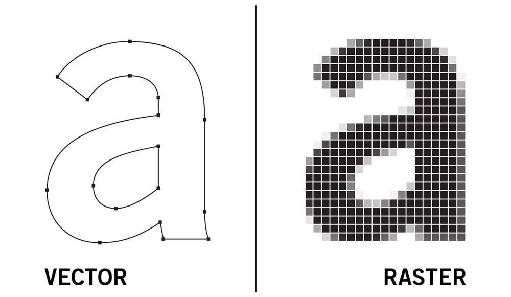
What is raster image ?
A raster image is a type of digital image that represents a two-dimensional picture as a rectangular grid of pixels. Each pixel, or picture element, contains a specific color value, and together, these pixels form the complete image. Raster images are commonly used in digital photography, computer graphics, and various display mediums
What is a vector image ?
A vector image is a digital image created using mathematical equations to define points, lines, and curves. Unlike raster images, which are composed of pixels, vector images can be scaled and resized without losing detail
Photopea
The first tool i used for editing was Photopea
Photopea is a free online image and graphics editor that works directly in your web browser. It supports both raster and vector graphics and can be used for simple or complex design tasks and as a simple alternative to Adobe Photoshop. With Photopea you can resize images, touch up photos, create illustrations and graphics, design webpages, and more, all without needing to install any software.
Link to website : https://www.photopea.com/
My idea was to remove background from an image of a coffee cup and place that cup on my table using some simple steps
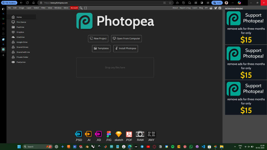
Open the website
- To start a new project press “ New Project”
- To open an existing file in your local storage click “Open from computer”
To use an existing template press ”Template”
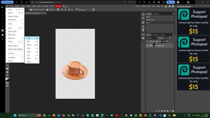
Open the file you want to edit from your local storage
- Right click and click remove background
- Then save the background removed file as PNG
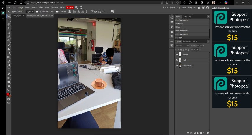
- Now open the picture you want to overlay the coffee
- Drag and drop or open the file
- Then resize the image to scale and place it in appropriate position
- For moving and scaling a layer “ ctrl + alt + T “
To learn more :Photopea Tutorials
Paint
Paint is a powerful but intuitive image editing app that has been a favorite on Windows. Quickly create and edit your masterpieces with the built-in tools, and when you’re ready, save your files in almost any format and share them anywhere.
Here my idea was to take a picture of my earphone and remover background and add a text
Open the pant app
- This are all the tools that are available in the paint app

- Tools I have used in this project
- Rotate : To rotate the imported
- Remove background : To remove background from selected image
- Eraser : To erase and remove unwanted parts from image
- Text : To add text to the image
- Color picker : To select a specific color from the image
- First import the image you want to edit by drag and drop or file >> open >> select file from storage
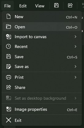
- After importing rotate the image using the rotate tool to the correct orientation
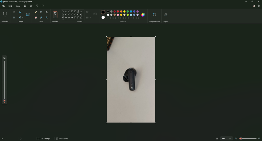
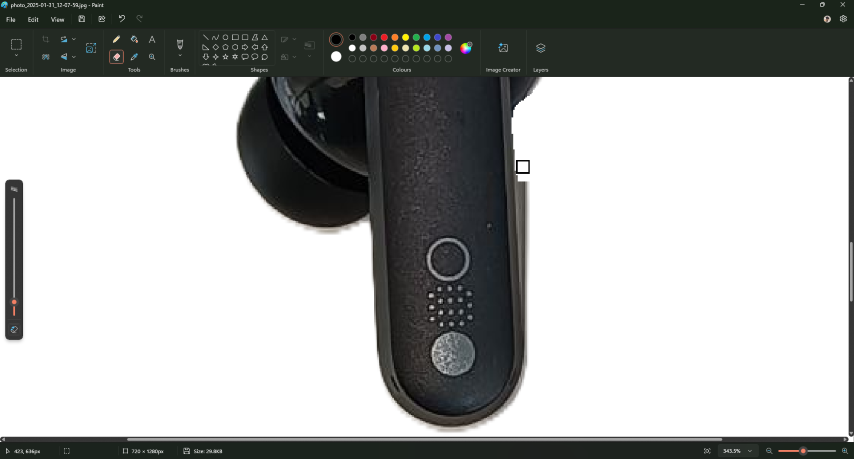
- Using the erase tool remove the unwanted parts from the image and refine it too your satisfaction
- Using the text tool add the required text and position it .
- Select the text and change the font ,font size etc…

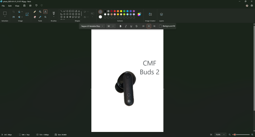
- Using the basic tool made some basic edits too make the necessary edits
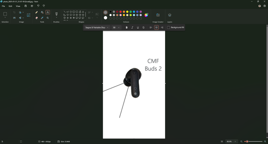
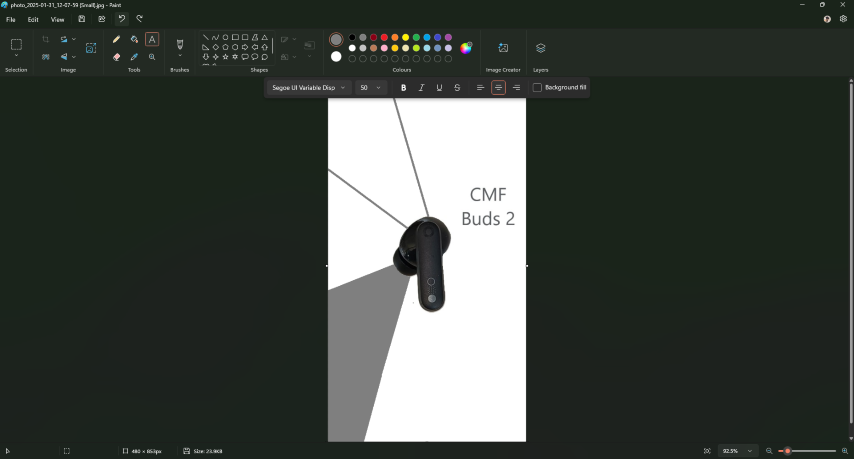
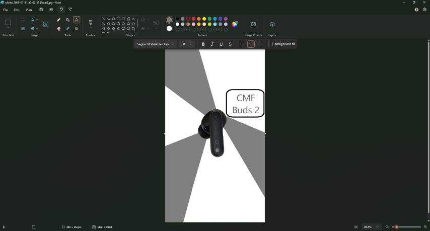
- Due to poor edge detection this happens
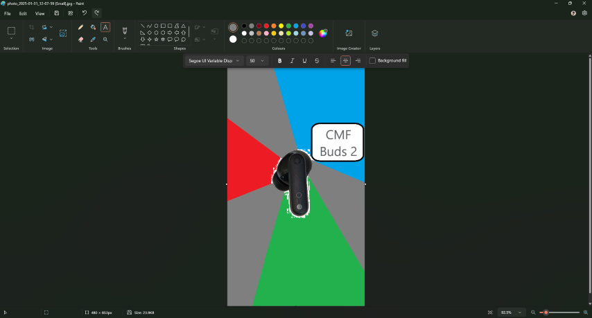
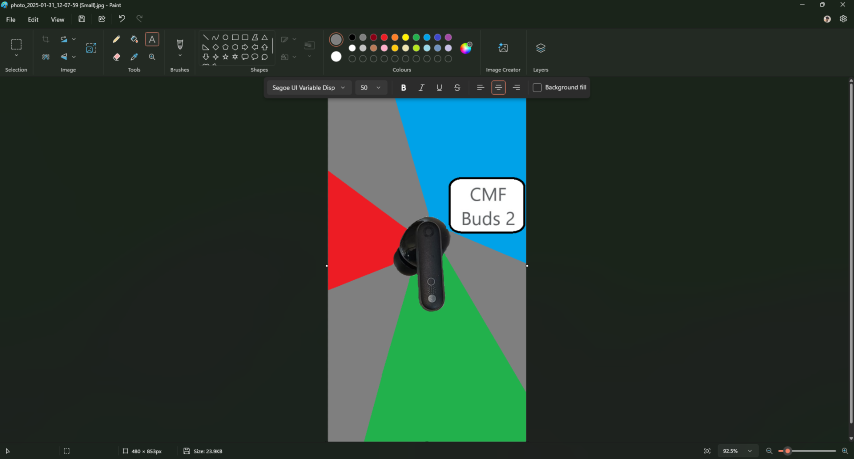
- After pains taking process of manual edge painting this is the final output
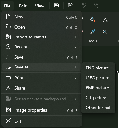
- Save the file in your preferred format
- Final result
Note : I don't prefer this app for major poster creation ,this is useful for painting.
To learn more : Ms Paint Tutorial | PPT
Inkscape
Inkscape is a vector graphics editor. It is used for both artistic and technical illustrations such as cartoons, clip art, logos, typography, diagrams, and flowcharts. It uses vector graphics to allow for sharp printouts and renderings at unlimited resolution and is not bound to a fixed number of pixels like raster graphics. It is free and open-source software released under a GNU General Public License (GPL) 2.0 or later.
Inkscape uses the standardized Scalable Vector Graphics (SVG) file format as its main format, which is supported by many other applications including web browsers. It can import and export various other file formats, including Adobe Illustrator (AI), Encapsulated PostScript (EPS), PDF, PostScript (PS) and PNG.[5]
Link : https://inkscape.org/
My idea was to generate a logo using AI and covert the image to vector and make the necessary edits
AI i used was open AI chat GPT
Link : ChatGPT
“ Generate a logo for my smart desk lamp with an eye ” this was the prompt I gave

Since the background color of the logo is dark we will have to take negative of the image for this we can use a online converter or editing tools like photo shop I used an online converter LunaPic to get the negative of the image
Link : [https://www6.lunapic.com/](https://www6.lunapic.com/)

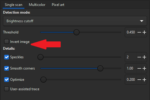
- There is an easier method
- You can insert an image with a dark image if it is the only option
- Then check the box that is shown in the image to easy invert bit map
- Next step is to open Inkscape and import the image
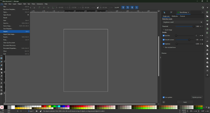
- Select the image that you need to convert to vector image
- When the bit image import window appear press ok without changing any thing
- Move and resize the image to fit inside the template
- Right click and press on the Trace bit map
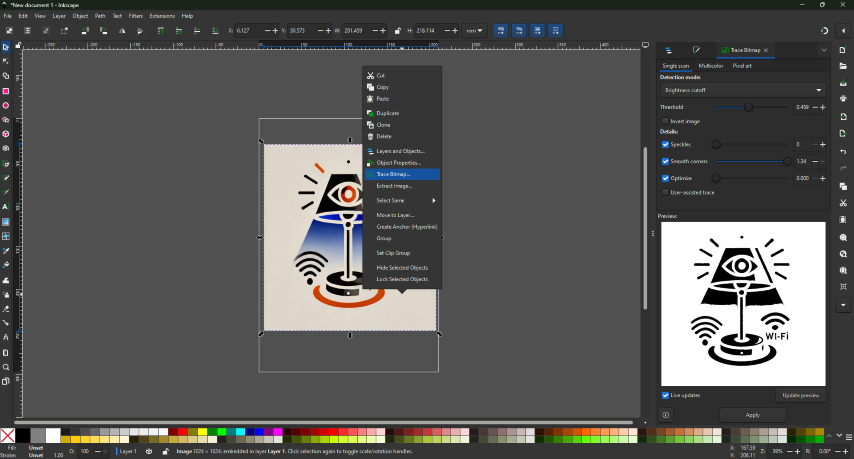
- Adjust the threshold values until the desired vector is obtained
- Press the Apply button
- Then select the image we imported and delete that image
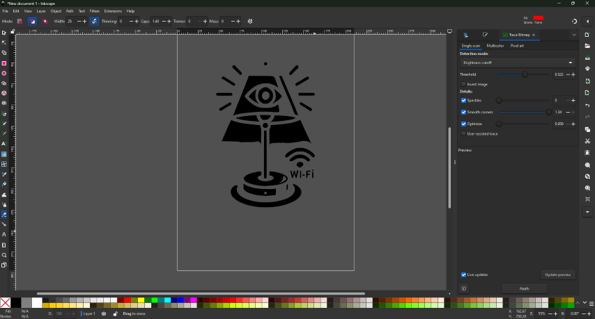
- Using the eraser tool from the left toolbar on remove any unwanted parts
- To increase the size of the tool and to change other properties of the tool use the top tool bar
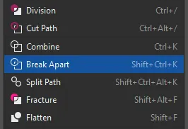
- Then sect the image and in path use beak apparat to make each part of the image separate
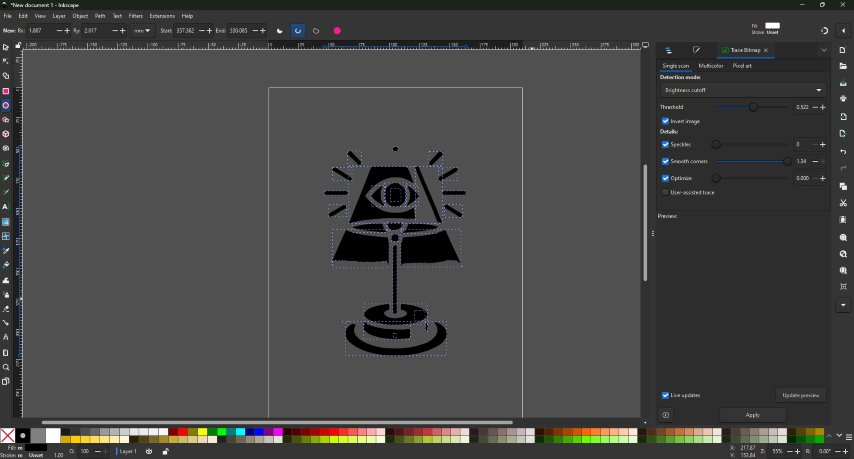
- To adjust the color select the shape and from the bottom section select the colors to you liking
- Then for adding text from side bar select the text tool from the left side tool bar
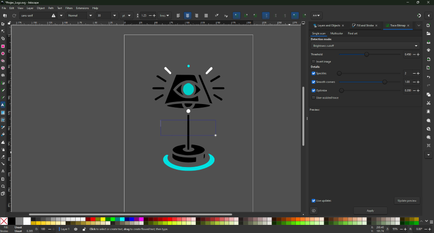
- when you select the tool and start adding your text from the top tool bar you can select the alignment, font size, font style etc.

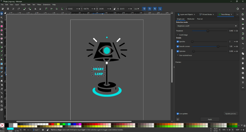
- This is the final result output

- Then save the image SVG
To learn more : Learn | Inkscape
Canva
Canva is an Australian multinational software company that provides a graphic design platform that provides tools for creating social media graphics, presentations, postcards, promotional merchandise and websites. Launched in Australia in 2013, the service offers design tools for individuals and companies. Its offerings include templates for presentations, posters, and social media content, as well as functionalities for photo and video editing.
Link : https://www.canva.com/
My idea was to create an aesthetic poster for an ear phone that I have
- I first took a picture of my earphone in a well lit environment
- Then imported the image into a back ground remover app Link : https://www.remove.bg/
- If you have a premium account in Canava this feature is available in the app
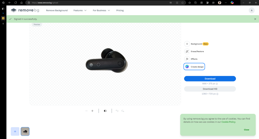
- Then open the canva app

- To create a new design press the button on the top left

- Then a window pops up select the type of design needed
- There a bunch of templates available which or you can start from scratch

- select a template that you like
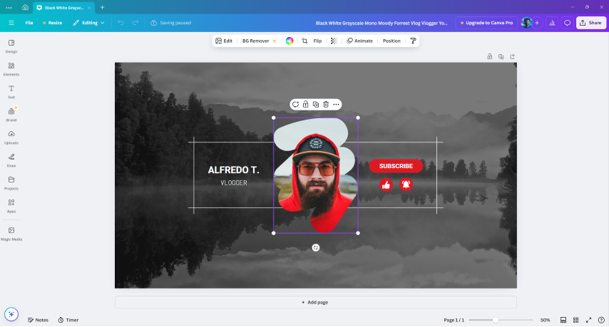
- I select one that I like ”Thanks Alfredo for making such a beautiful template”
- Then I removed all the unwanted assets from the template by selecting and deleting it
- Then i imported the image from which i removed the background from by simple drag and drop
- Also i mirrored one image
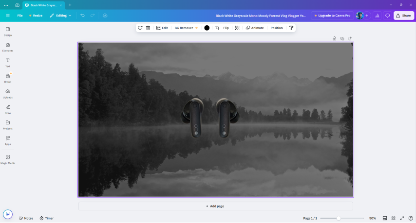
- After that I imported a simple png logo from the web of the brand from Link : https://in.nothing.tech/
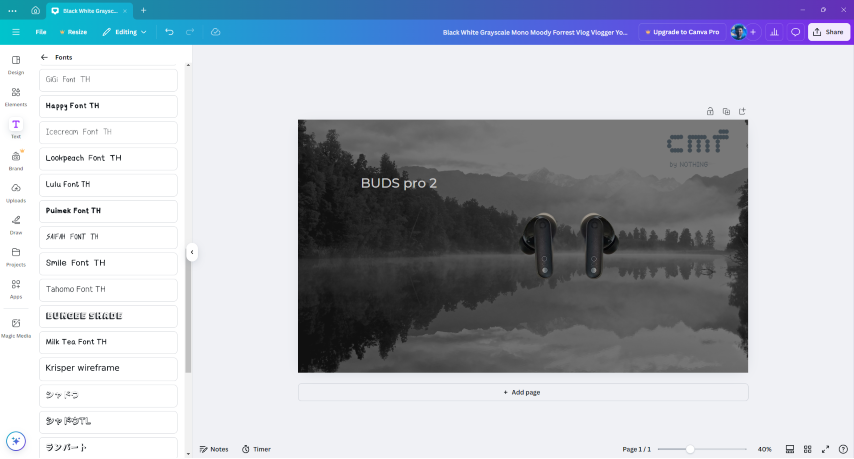
- Then from the left side bar I selected the text tool to add text and from the tool bar that appears on the top select the color
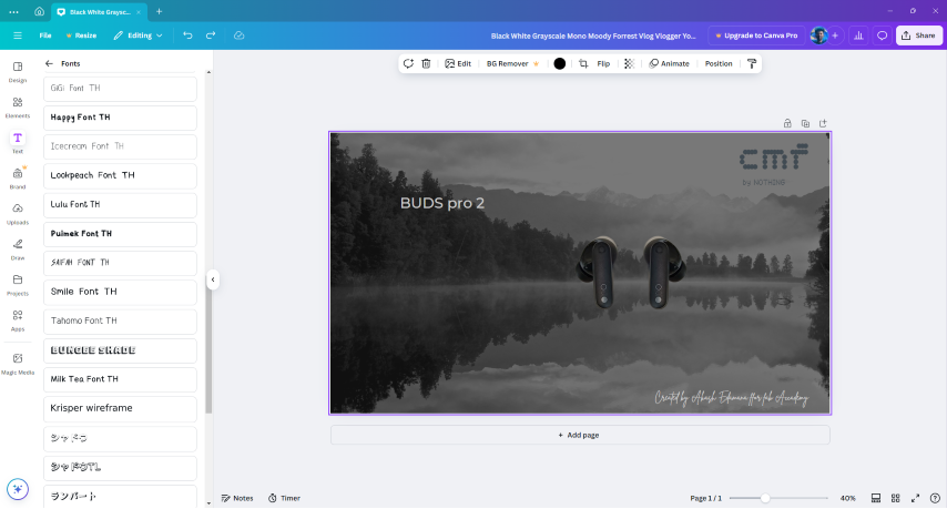
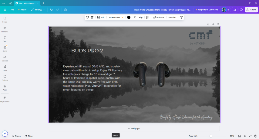
- Then by using the same method I added a text “Designed by..” on the bottom in a different font and a small description of the product.
- This is my final output
- For saving press on the share button on the top right region

- And from the window that appears press the download button and select the download location
To learn more : Tutorials
3D Design
Design History
The Design History Tree, often referred to as the feature tree or model tree, represents the chronological backbone of parametric CAD modeling, providing a comprehensive record of how a design evolves from initial concept to final form.
Representations in 3D design
Boundary representation(BRep)
B-rep or boundary representation is a rendering technique for solid modeling. It is a popular approach to create a solid model of a physical object. Brep is that a three-dimensional object model is enclosed by surfaces or faces and has its own interior and exterior. It describes the shape as a collection of surfaces which separate its interior from the external environment. It is suitable for complex designs, Polygon facets are one of the examples of boundary representation.
Function representation(FRep)
Function Representation (FRep or F-Rep) is used in solid modeling, volume modeling and computer graphics. FRep was introduced in "Function representation in geometric modeling: concepts, implementation and applications" as a uniform representation of multidimensional geometric objects (shapes).
Volume representation(VRep)
Volume representations, often referred to as VRep (Volume Representation), are a method used in computer graphics, computational geometry, and 3D modeling to represent 3D shapes or objects using volumetric data. Unlike surface-based representations (e.g., meshes or NURBS), which define only the outer surface of an object, volume representations describe the interior as well as the exterior of a 3D shape.
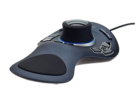
3D Input devices
3D input devices are fascinating tools that allow users to interact with digital 3D environments in a more intuitive and immersive way. These devices can be used in various fields, including computer-aided design (CAD), virtual reality (VR), gaming, and more.
Some advanced input devices


What is Graphical User Interface (GUI)?
A system of interactive visual components for a computer or system software is called a GUI (graphical user interface). GUI is the interface that uses graphical elements to let people interact as per requirement with electronic devices including computers, laptops, tablets, and smartphones. In terms of human-computer interaction systems or technology, it's a very important component of software application programming since it substitutes actions for the text-based commands in the system. Whether it's a text file, object, image, or video as per requirement, it displays all types of required content a user could envision in the system. Additionally, it can be featured in the gaming platform where the resolution is visible or optimal.
Scripting
Scripting in 3D modeling refers to the use of programming languages or scripts to automate tasks, create custom tools, or manipulate 3D models and scenes within 3D software. Instead of relying solely on the graphical user interface (GUI) of a 3D modeling application, scripting allows users to write code to perform complex or repetitive tasks more efficiently.
Hardware Description Languages
Hardware Description Languages (HDLs) are specialized computer languages used to describe the structure, behavior, and timing of electronic circuits, particularly digital logic circuits. They are essential tools in the design and simulation of application-specific integrated circuits (ASICs) and field-programmable gate arrays (FPGAs)1.
Key Principles and Purpose
HDLs enable designers to create precise, formal descriptions of electronic circuits, allowing for automated analysis, simulation, and synthesis into netlists. These netlists specify the physical electronic components and their connections, which can then be used to produce integrated circuits1. HDLs are integral to electronic design automation (EDA) systems, especially for complex circuits like microprocessors and programmable logic devices1.
OpenSCAD
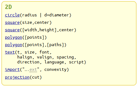
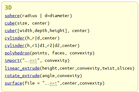
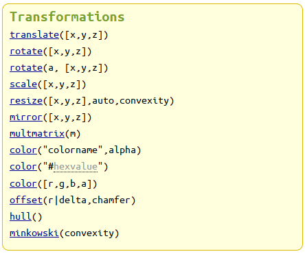
OpenSCAD is a free software application for creating solid 3D computer-aided design (CAD) objects. It is a script-only based modeller that uses its own description language; the 3D preview can be manipulated interactively, but cannot be interactively modified in 3D. Instead, an OpenSCAD script specifies geometric primitives (such as spheres, boxes, cylinders, etc.) and defines how they are modified and combined (for instance by intersection, difference, envelope combination, or Minkowski sums) to render a 3D model. As such, the program performs constructive solid geometry (CSG). OpenSCAD is available for Windows, Linux, and macOS.
Download Link : https://files.openscad.org/OpenSCAD-2021.01-x86-64-Installer.exe
Cheat sheet : OpenSCAD CheatSheet
This is my first time trying out a software that can model 3d objects wit code, So will be comparatively challenging for me in such a small time frame so i will be tying out a simple design using openSCAD
Tutorial I watched : https://www.youtube.com/watch?v=dzzFOU_Ggrs
Syntax
2D Syntax
3D Syntax
Transform Syntax
Boolean Operations

For making a cube of length 40 ,Breadth 40 and Height 500 and the false here represent the origin of the object if you put true the origin will be in the center of the 3D space
cube([40,40,500],false);
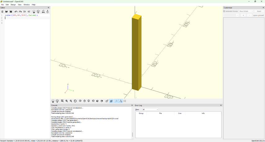
- Similar to this the small cube on top of it is to be added and a translation is added to locate the cube on top of the previously created body
translate([10,10,500])
      cube(30,false);
Note : while using the translation the object after this line of code is translated if you want more parts then enclose the code of the object inside {}
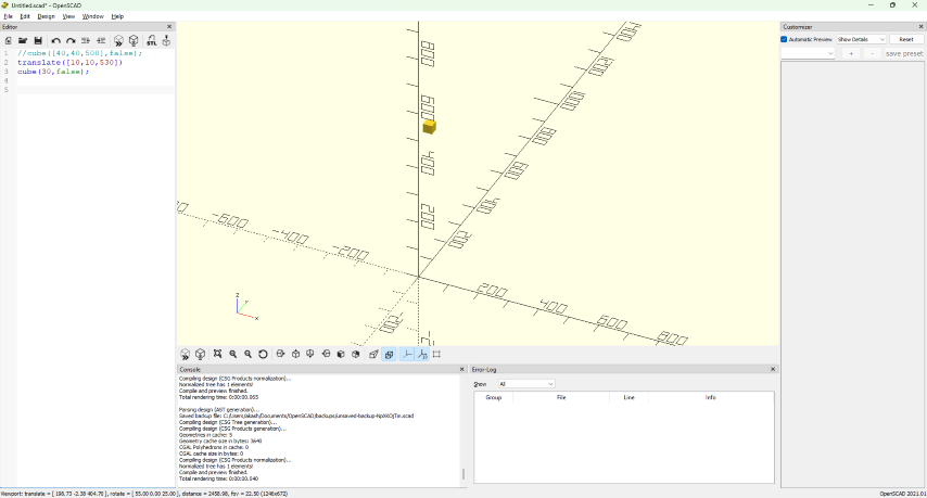
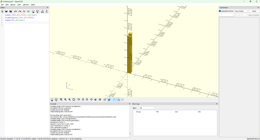
- Then made one or leg with a translate
cube([40,40,500],false);
      translate([10,10,500])
      cube(30,false);
      translate([0,400,0]){
          cube([40,40,500],false);
          translate([10,0,500])
          cube(30,false);}
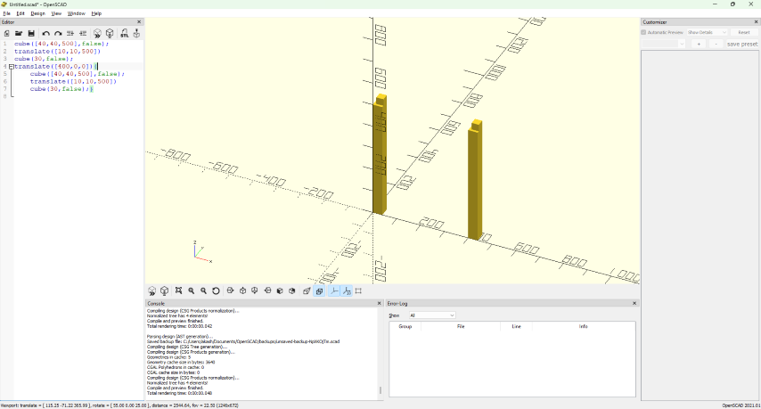
- Then using the mirror command
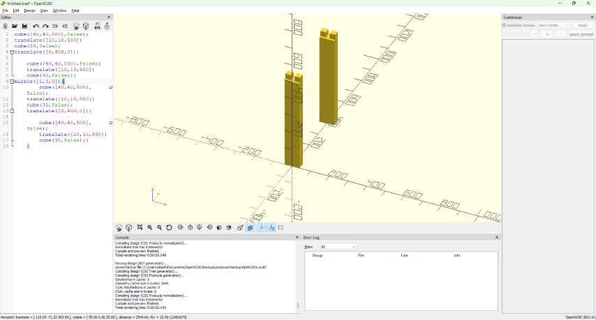
- Then put a translate for this too
cube([40,40,500],false);
      translate([10,10,500])
      cube(30,false);
      translate([0,400,0]){
          cube([40,40,500],false);
          translate([10,0,500])
          cube(30,false);}
      translate([400,0,0]){

          mirror([1,0,0]){
                  cube([40,40,500],false);
              translate([10,10,500])
              cube(30,false);
              translate([0,400,0]){

                  cube([40,40,500],false);
                  translate([10,0,500])
                  cube(30,false);}
              }
          }
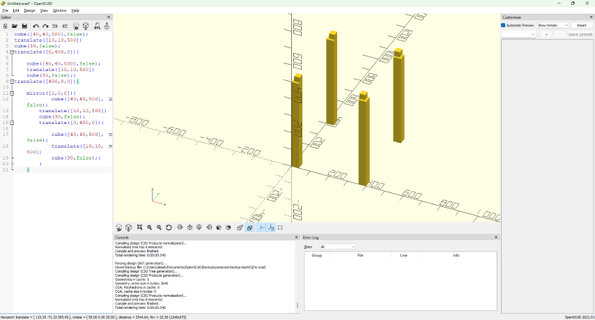
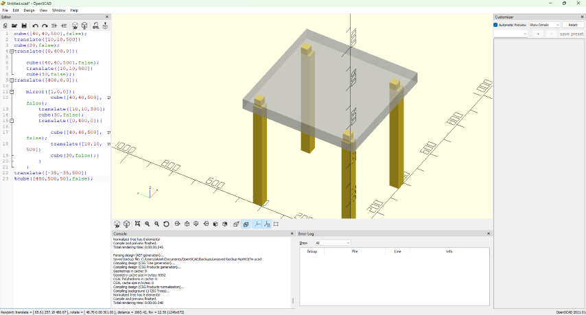
- Then to add the top plate
cube([40,40,500],false);
      translate([10,10,500])
      cube(30,false);
      translate([0,400,0]){
          cube([40,40,500],false);
          translate([10,0,500])
          cube(30,false);}
      translate([400,0,0]){

          mirror([1,0,0]){
                  cube([40,40,500],false);
              translate([10,10,500])
              cube(30,false);
              translate([0,400,0]){

                  cube([40,40,500],false);
                  translate([10,0,500])
                  cube(30,false);}
              }
          }

      translate([-35,-35,500])
      cube([480,500,50],false);
- This is the final output
Rhino 8
Rhinoceros is a commercial 3D computer graphics and computer-aided design (CAD) application software that was developed by TLM, Inc, dba Robert McNeel & Associates, an American, privately held, and employee-owned company that was founded in 1978. Rhinoceros geometry is based on the non-uniform rational B-spline (NURBS) mathematical model, which focuses on producing mathematically precise representation of curves and freeform surfaces in computer graphics (in contrast to a polygon mesh mathematical model).
Link : Rhino - Downloads
Voronoi
In mathematics, a Voronoi diagram is a partition of a plane into regions close to each of a given set of objects. It can be classified also as a tessellation. In the simplest case, these objects are just finitely many points in the plane (called seeds, sites, or generators). For each seed there is a corresponding region, called a Voronoi cell, consisting of all points of the plane closer to that seed than to any other. The Voronoi diagram of a set of points is dual to that set's Delaunay triangulation.
Here I am trying out grass hopper in Rhino
Rhino 2D and Grass Hopper
- Open Rhino
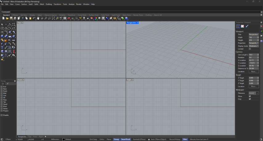
- From the top toolbar open grass hopper

- Then go to mesh >> Triangulation >>
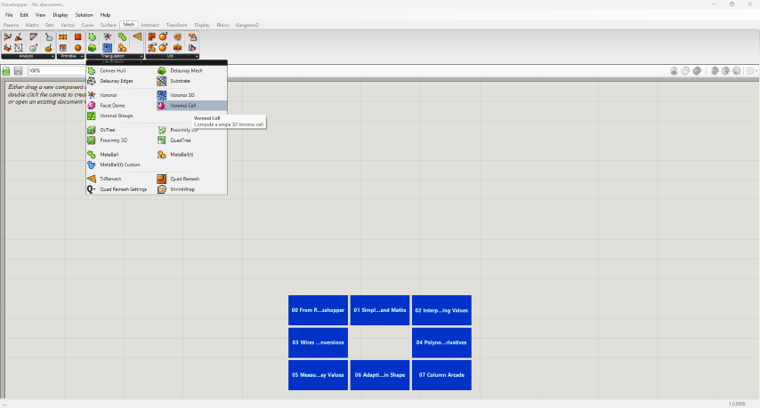
- Drag and drop Voronoi
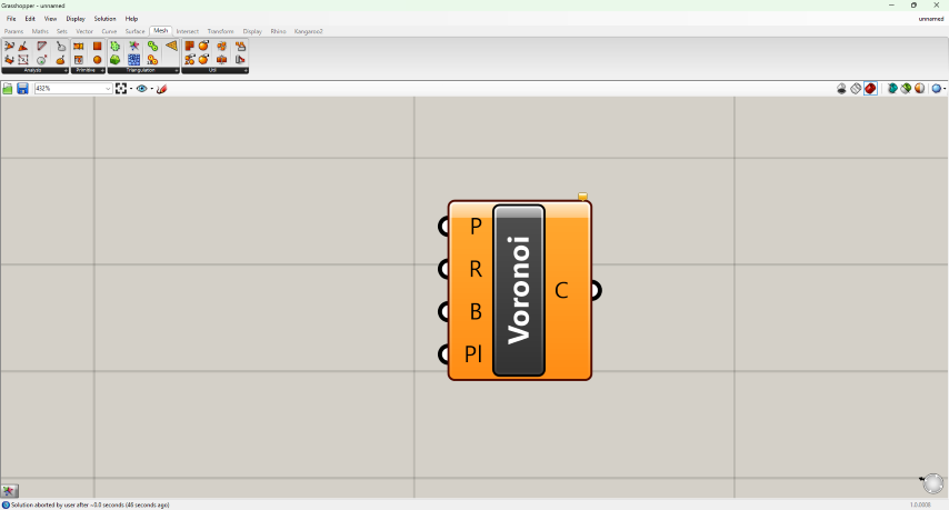
- Then need to make some random points in 2d space one option is to manually put some points in the 2D plane easier option is to do it through grass hopper
on the top go to vectors >> Grid >> populate 2D
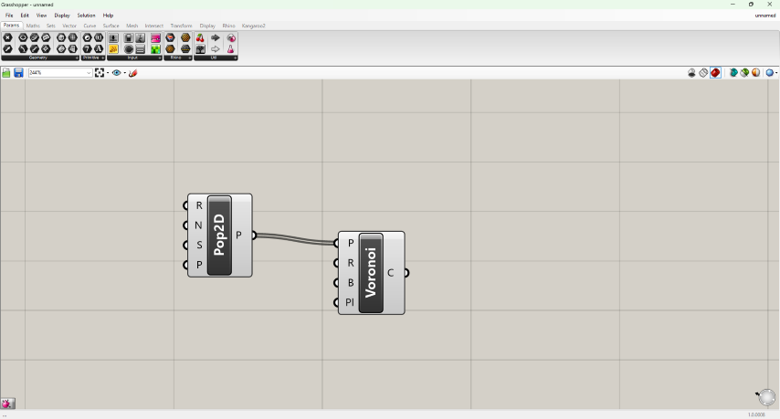
which will give an output like this
Then connect the p of the pop2D to P of Voronoi
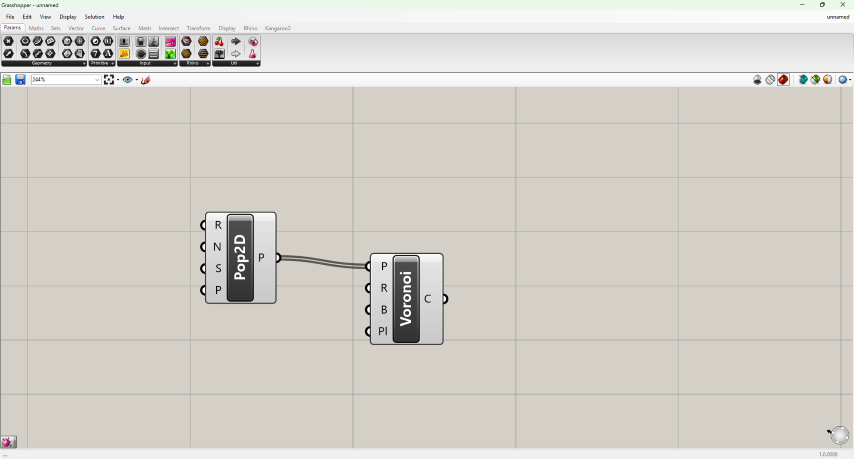
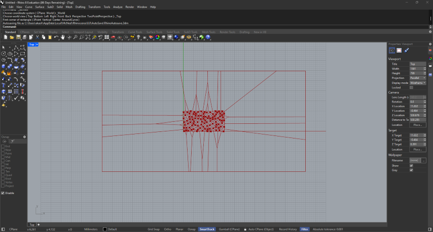
Then to contain all these points and the Voronoi inside a rectangle
double click and type rectangle “ double click is like a search option used to search for nods inside grass hopper
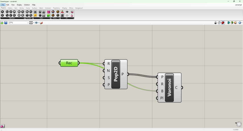
Then right click and select set rectangle
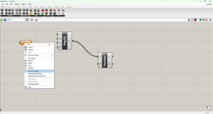
- Then in the command region of rhino first type in the initial position of the rectangle press enter
- Then type in the width and press enter then type in the height
Then in grass hopper connect the rectangle node to R of the Pop2D and to the R of Voronoi node
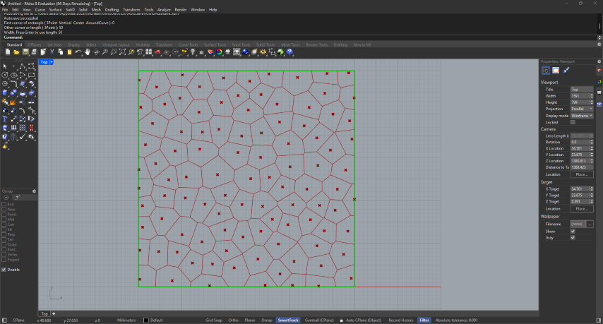
Then to adjust the density of the mesh add a slider and connect it to N on the Pop2D
- By increasing the value in slider the density increases in
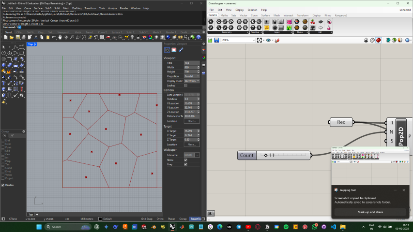
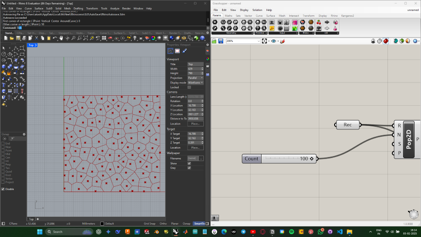
Rhino 3D and Grass Hopper
Here i was trying to make a 3D Voronoi patterned cube and export it
- Similar to 2D open rhino and open grass hopper
- From the top tool bar from the mesh section drag and Voronoi 3D cell this is a cell that create Voronoi patterns
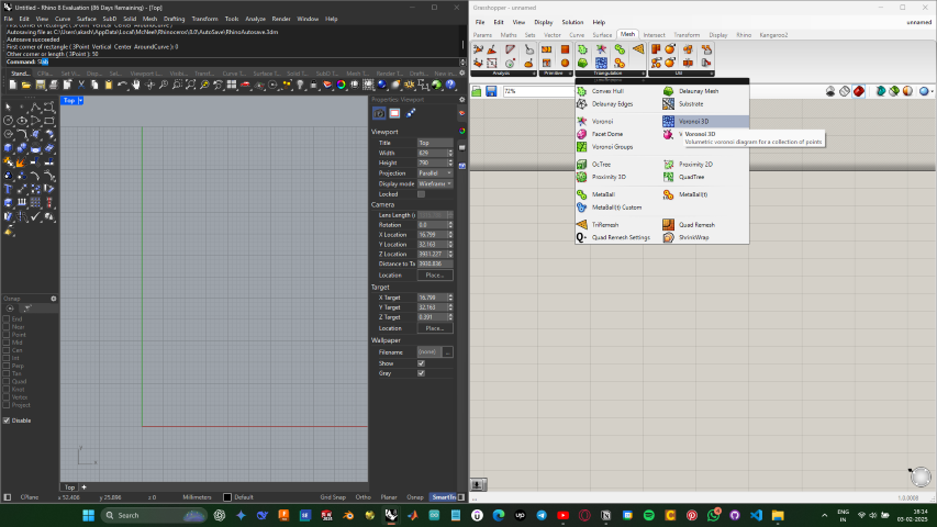
- Then from the top tool bar in the vector section insert populate 3D cell this cell created a set of random pattern
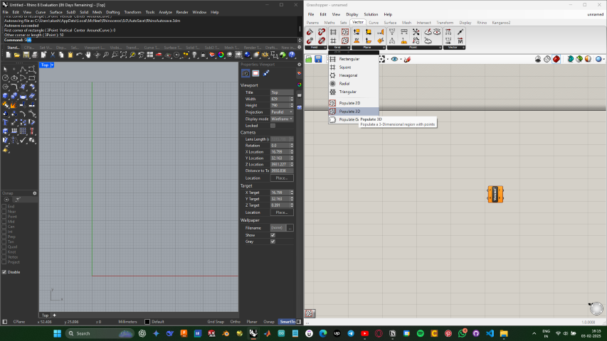
- Then connect the P of Pop3D to P of Voronoi
- Then from params add a box cell
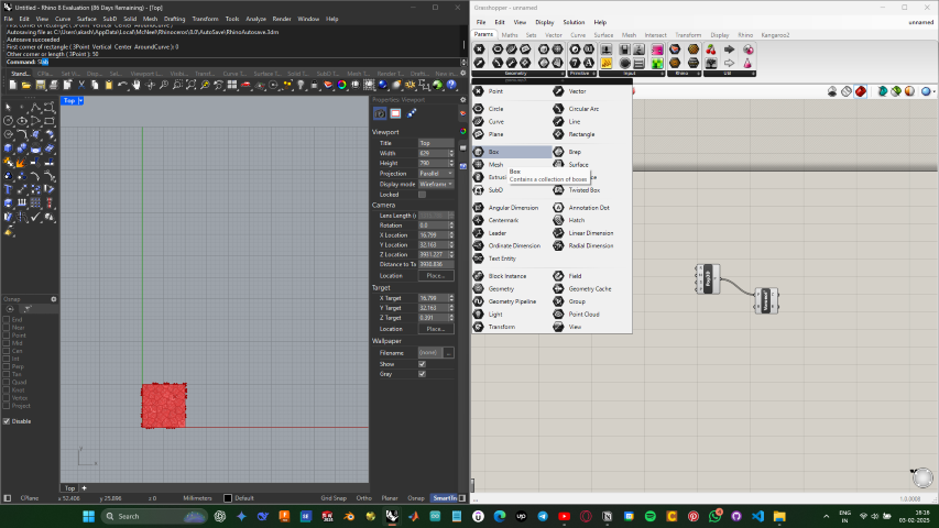
- Then connect the box to R of the Pop3D and to B of Voronoi
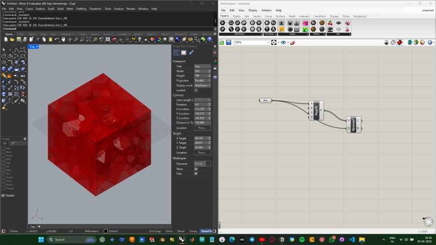
Note : I was not able to convert this to a 3D, due to the lack of time I was not able to spend more time on this and give a proper output
SOLIDWORKS
SolidWorks (stylized as SOLIDWORKS) is a brand within Dassault Systèmes that develops and markets software for solid modeling computer-aided design (CAD), computer-aided engineering (CAE), 3D CAD design, collaboration, analysis, and product data management.[2] The company introduced one of the first 3D CAD applications designed to run on a desktop PC
Link : https://www.solidworks.com/sw/support/downloads.htm
Solid works is a cad design software I am very familiar with , due to the lack of time my idea was to design a simple cup
- Open solid works application
- Solid works is a tool where there is a separate file format for parts and assembly
- In this project my plan is to design cup which does not any sub component so I am using part file
From the window that pops up select part
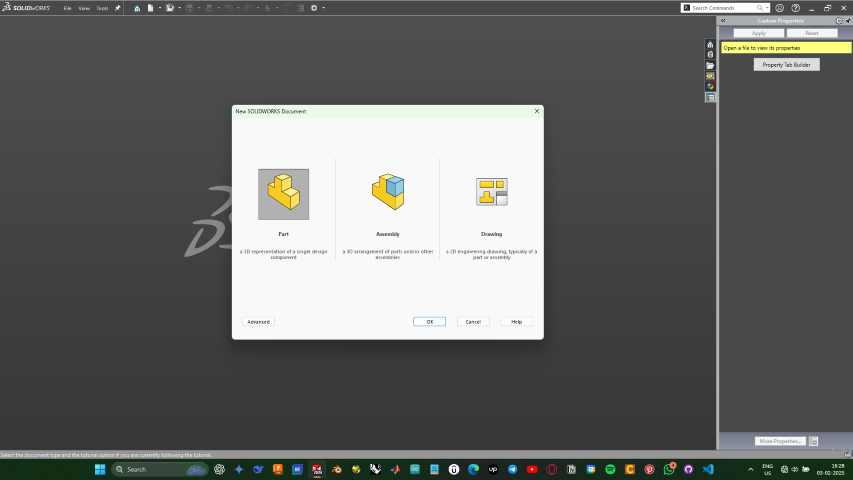
Then from the top tool bar select the sketch tool
Then select a plane where you want to make the sketch
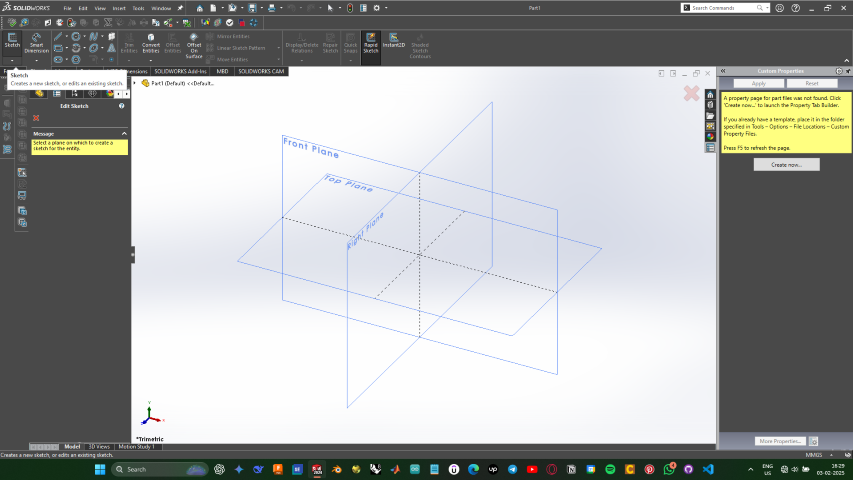
In my case I selected the top plane for making the sketch
- While making sketches make sure the sketch is always defined when the sketch is defined the lines will appear black or it will be blue
Depending on the size of the base of the cup make a circle
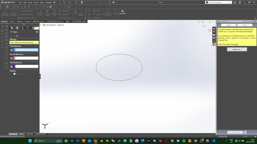
Then from the top tool bar select the dimensions tool , select on the circle make and give dimensions for the circle
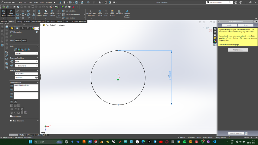
Then from the top tool bar click “Exit sketch”
- The. Go to the features section in the top tool bar
- Then from the top tool bar middle region select the reference geometry tool
- Then select the top plane
- And in the left tool bar that appeared input and offset value which will be the height of the cup
- Then from the top tool bar go to sketch and from top left select the sketch tool then select the newly created plane
- Then repeat the same process of making circle on the new plain
- Since I am making a slightly cured class I am going to use the loft tool and a curve have to be created for the guide the loft tool
Make a new sketch on the right plain by using the curve tool make a curved line that connects the two circles and exit the sketch
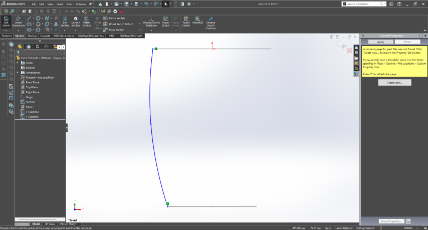
Now go into the features section from the top tool bar
- And open the loft tool
First select the two circles and then on the left tool bar that appeared select the guide curve section and select the curve made
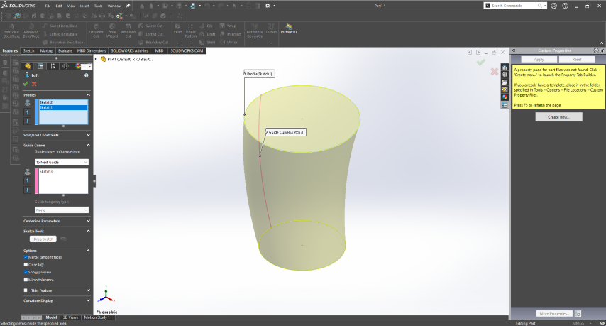
In features section select select the fillet tool
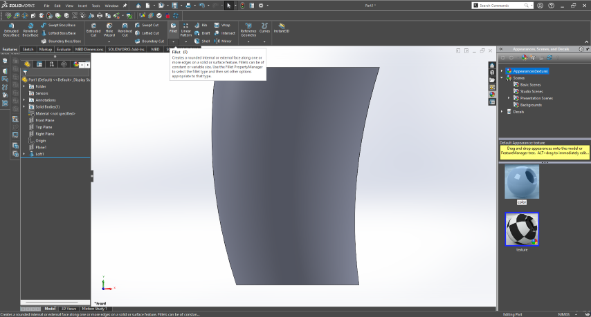
Then select the face or edge where you want to make the filet
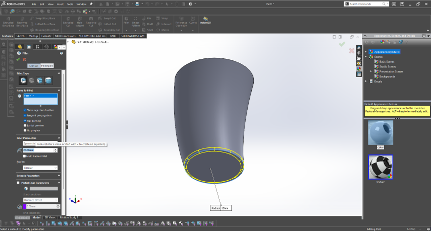
- Now to make the body hollow from the top toolbar select the shell toll
- First select the face where you want to be open then left tool bar select the next section and then select the body and press the tick mark
- The next part is to make the handle
- Select the right plane where you wan to make the handle
- Then make a sketch of the shape of the handle
Use the offset tool from top tool bar make the copy of the curve first made for the handle
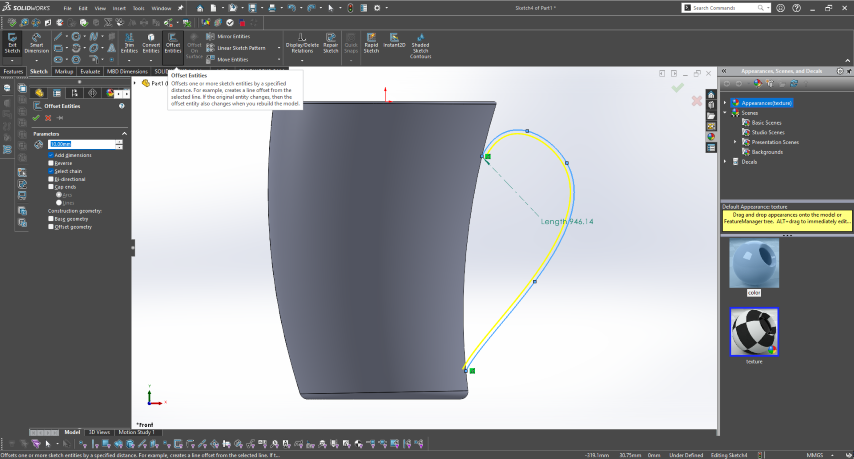
Then from the top tool bar select the extrude tool and select the sketch
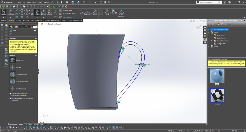
Make sure the sketch is closed
- Then extrude to both sides
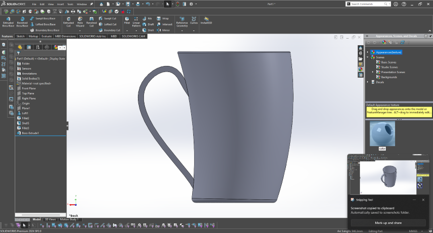
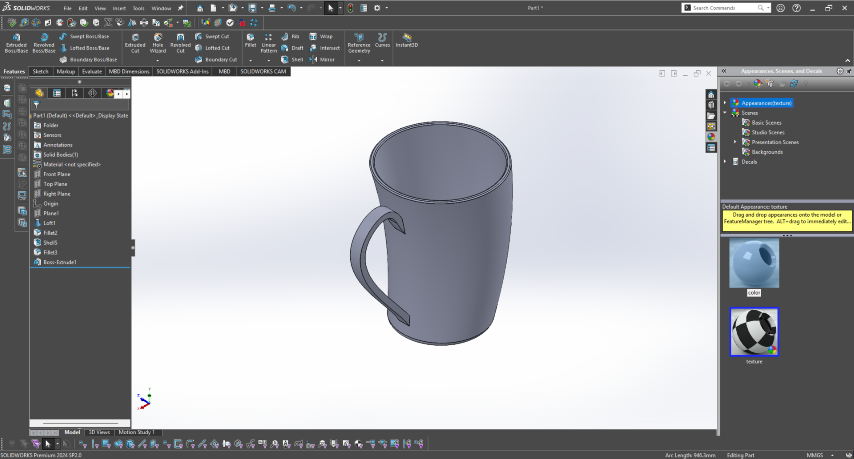
- Final output
Fusion360
Autodesk Fusion is a commercial computer-aided design (CAD), computer-aided manufacturing (CAM), computer-aided engineering (CAE) and printed circuit board (PCB) design software application, developed by Autodesk. It is available for Windows, macOS and web browsers, with simplified view-only applications available for Android and iOS. Fusion is licensed as a paid subscription, with a free limited home-based, non-commercial personal edition available.
Link : Download Autodesk Fusion for Free | Free Trial | Autodesk
Here i am designing the rough model of my potential final project
Here first click on the sketch tool
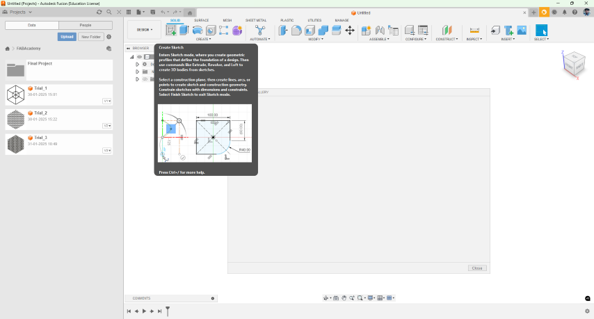
Then select the plane on which the sketch is to be made
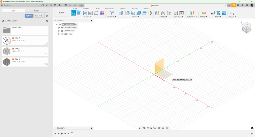
- Then from the top tool bar select the circle tool

- Then draw a circle on the origin with a specific dimension
- while drawing the circle if you type the diameter of circle it will come to effect
- Then press E or from the top tool bar go to the solids area and when use the extrude tool and select the circle and then extrude to the needed
- Then select the sketch tool and select the face where you want to create new sketch
- For creating the ring make two circles make two circles and press E and select the gap between the two circle and extrude to required height
- while extruding from the window that appears on the right side select join
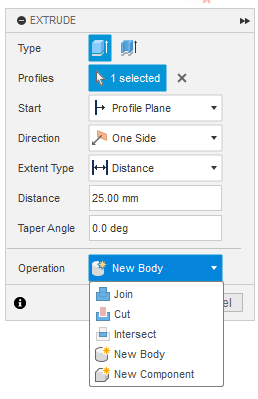
- Then make a new part similar mentored the only change is while extruding select operation as “New Body” or “New Component”
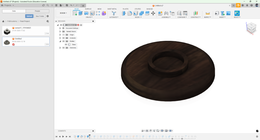
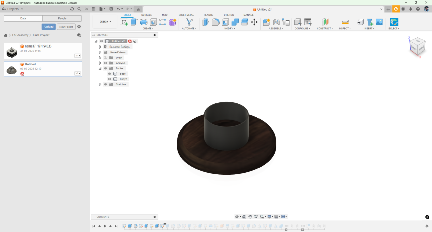
- Similarly create the rest of the parts
- Then to create the top cap using the revolve tool
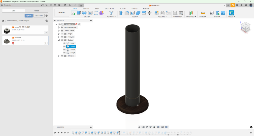
- For that make the sketch on front or right plane
- Then in the select the axis to revolve around as Z axis
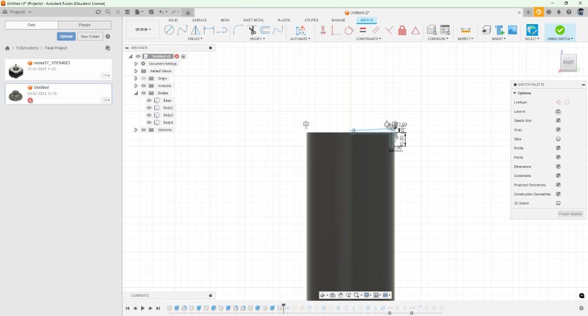
- For Making the hinge
- Make the sketch in Front or Right plane
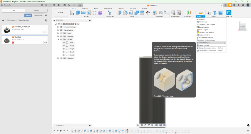
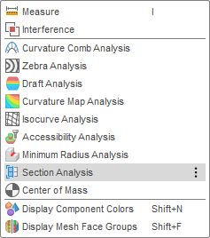
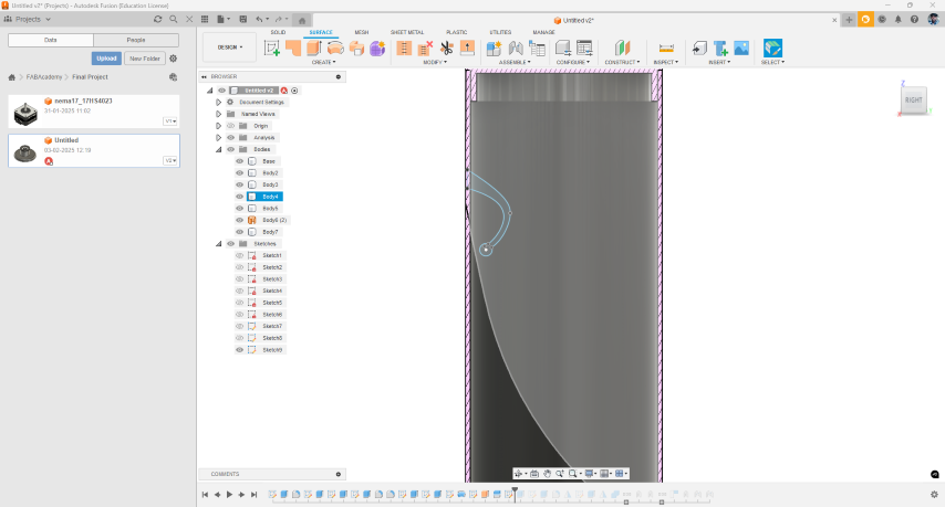
- To view inside a closed body we can use atoll called Section Analysis
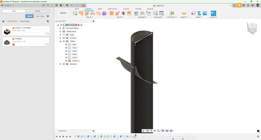
- To make curved cut
- From top tool bar in the surface section make a sketch in the right plane and extrude it to both sides
- Then using the in modify se the split body tool to cut the body along the surface generated
- To make the hinge
- Make the sketch of the hinge and extrude to both sides
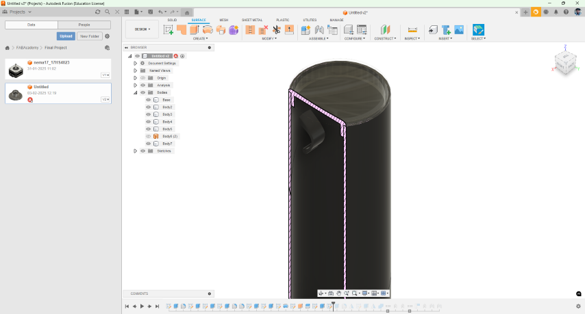
- Then in similar method make the pin where it slots into the bottom part
- Fillet the edges using the fillet tool from the top toll bar orby using the F shot cut
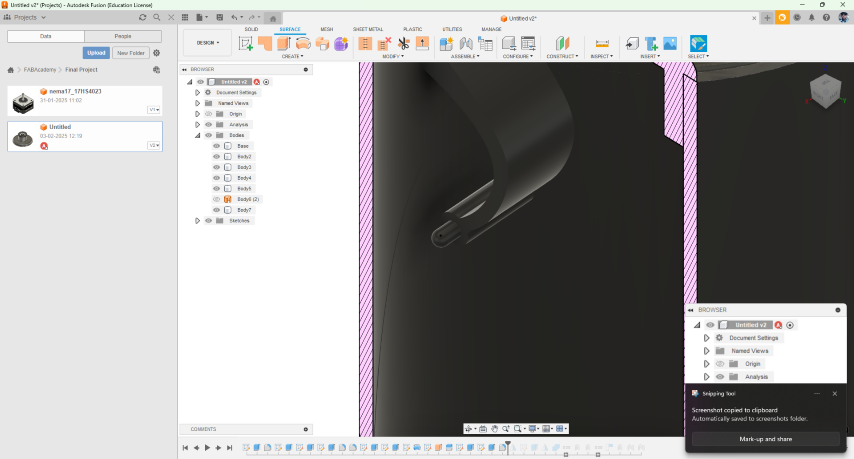
- For making the female part of the hinge make sketch on the plane where both parts come in contact and extrude to make the the part
- Use the mirror tool to make a copy of the part on the other side
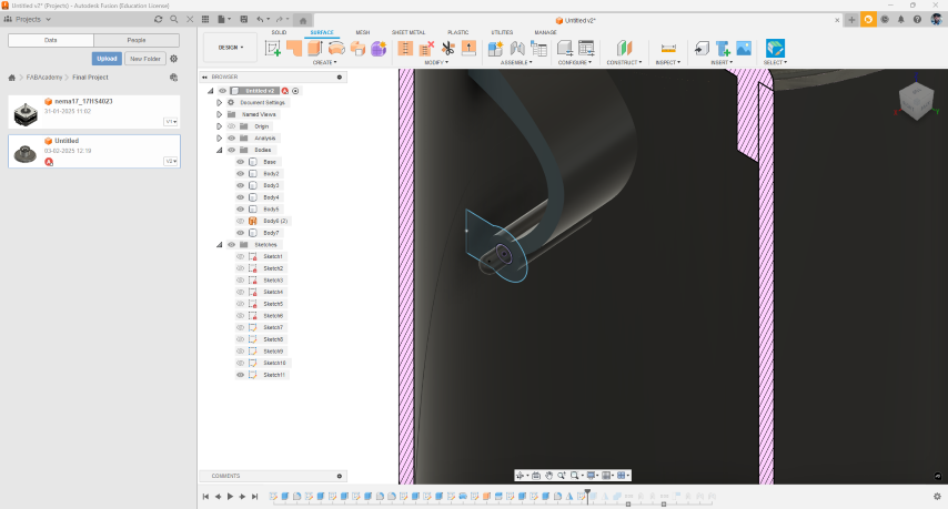
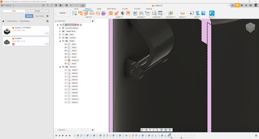
- Select all the bodies from the tree from the left section and convert them into components
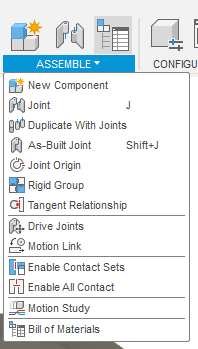
Then from the solid section go to the assembly section select the as Joint or As built joint two parts
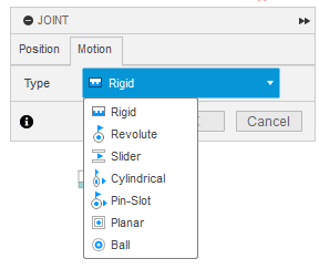
In joints to make a hinge select the coinciding plan or edge and in motion section select the type of motion needed
- Similarly in As Built joint too sect
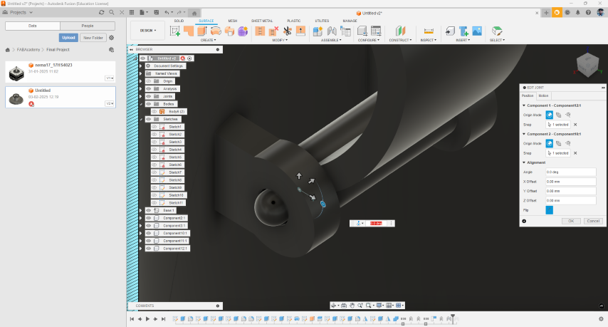
My Exploration of Geometric 3D Models
Rendering
Fusion
Here I rendered by Initial design of the project in fusion
- Here i made a basic render of the project in fusion
- From the top bar select render
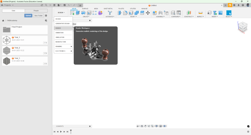
- Then the new window then on the top tool bar tools these tools appears
- The first tool here is an appearance tab where you can add the appearance
- The next tool is where you add the environment
- Then the the next tool helps to add a picture to a surface
- From the In-Canvas Render the first toll is where you can see a rendered view
- The next tool is in canvas render settings
- The next tool is get the image
- Then is the render tools the where you ender the final image

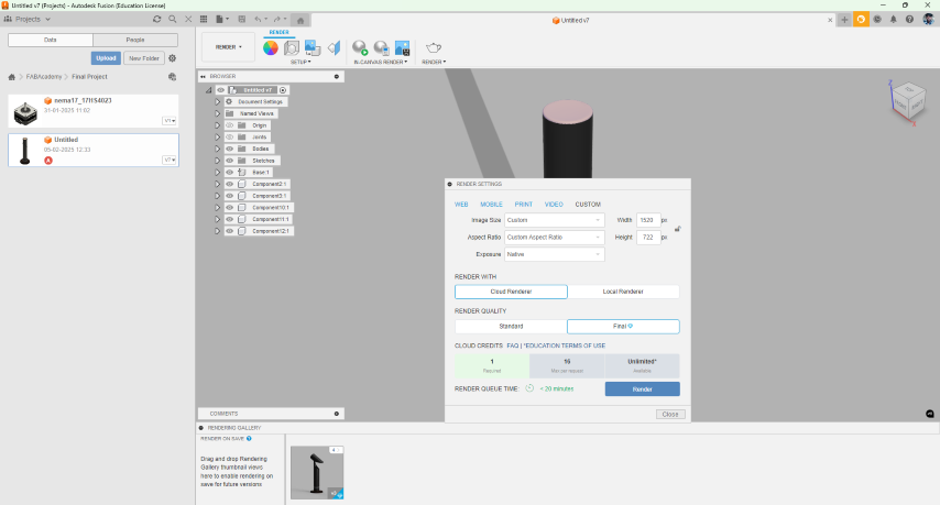
- This is window appears when click on the render button
- Here you can change the quality, Aspect ratio and other properties of the output
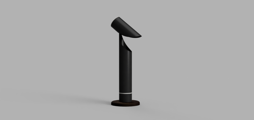
- This is the final output

Simulation using Fusion360
The Simulation workspace allows you to perform stress analysis to determine how loads lead to deformation and failure, helping you understand if and how the part will fail. You save time as you experiment with virtual design variations or adapt to changing design requirements.
Here my idea was to simulate a simple clamp using structural simulation in fusion360
- First design a simple clam in fusion
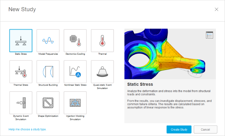
- Then go into to summation workspace from the top left drop down menu
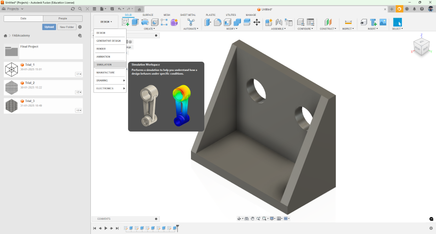
- From the new window that appeared select the type of summation needed
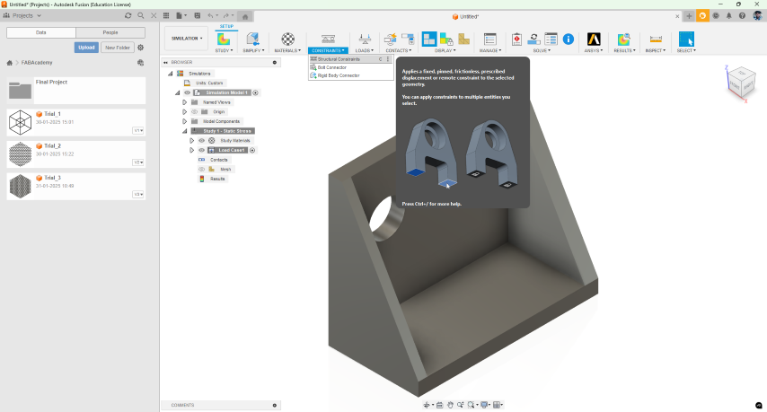
- Then select the constrain tool and select the faces which have to be constrained
- Then the next step is to set the load and the face where the load have to be applied
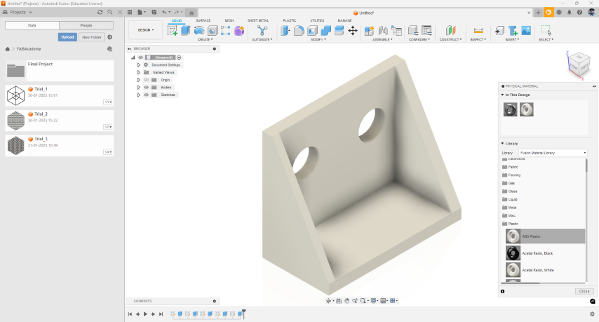
- Also add the the material from the design workspace
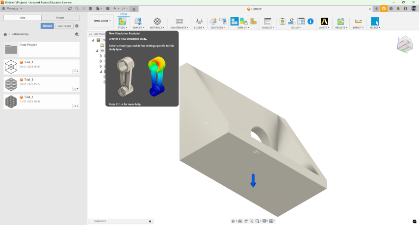
- Open the load tool from the top tool bar and select the face where the load have to be applied
- The arrow represents the direction of the force
- Then from the top toll bar check if there is any error
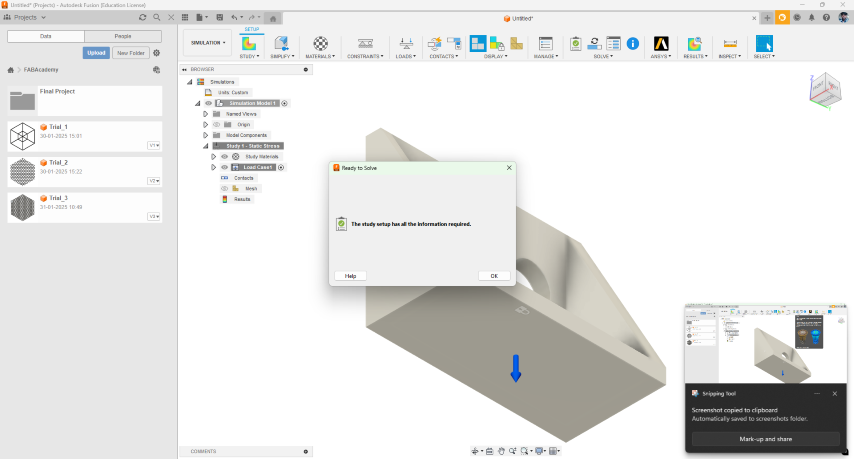
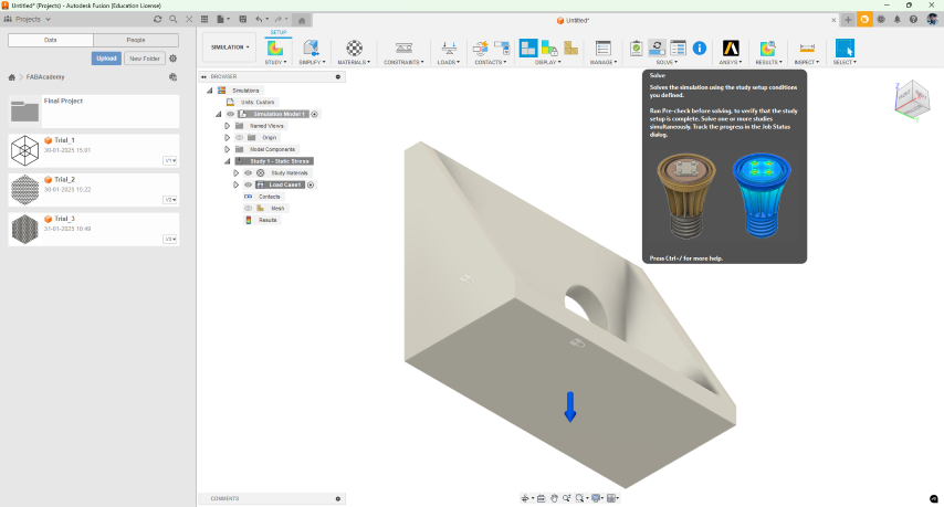
- The on the top tool bar select the solve button
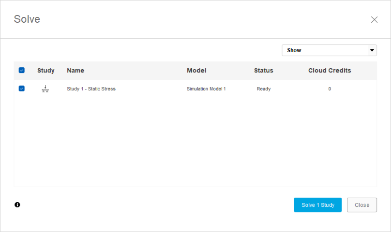
- Then this window appears
- Then do the study
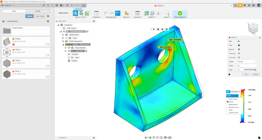
- Then to see the final result from the top tool bar select the result button
- Then in the results window from the right tools in the bottom section from the drop down section you can evaluate stress, strain ,displacement etc…
Animation
Blender Animation
Blender is the free and open source 3D creation suite. It supports the entirety of the 3D pipeline—modeling, rigging, animation, simulation, rendering, compositing and motion tracking, even video editing and game creation. Advanced users employ Blender’s API for Python scripting to customize the application and write specialized tools; often these are included in Blender’s future releases. Blender is well suited to individuals and small studios who benefit from its unified pipeline and responsive development process. Examples from many Blender-based projects are available in the showcase.
Here I used blender to animate my idea was to animate a simple product animation
- First import a the file int to blender
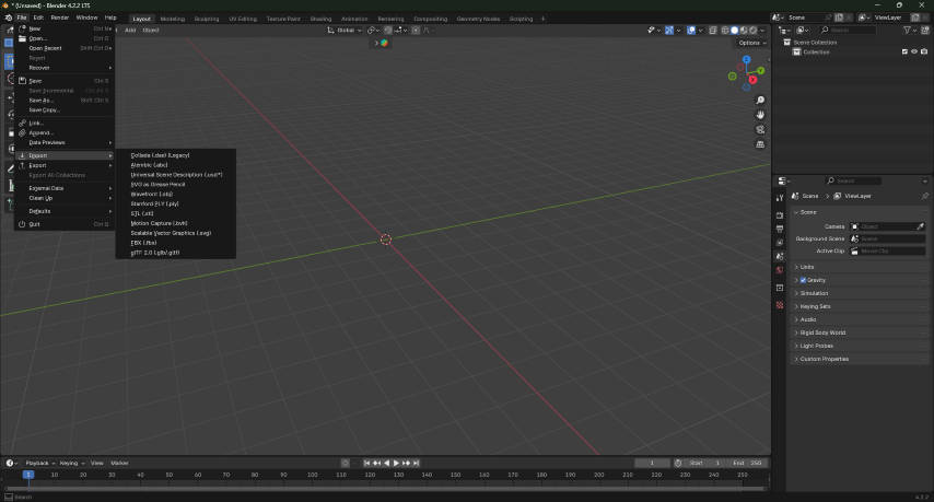
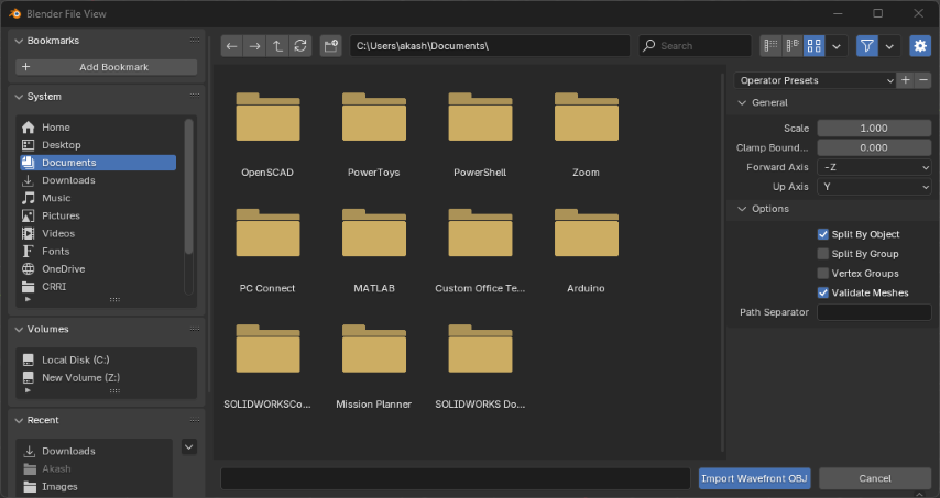
- many types of files can be imported into blender i imported obj also while importing select the checkbox split by group
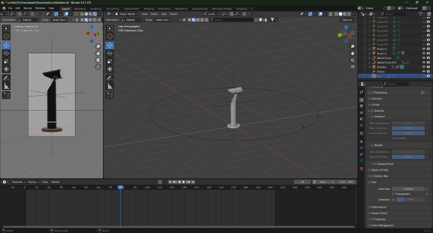
- Then I added a camera, light, empty and a circular curve to the environment
- Then select the camera then using then from the right tool bar select the constrain and add a constrain track to and select the empty to track to..
- Then add a clamp to constrain to the camera
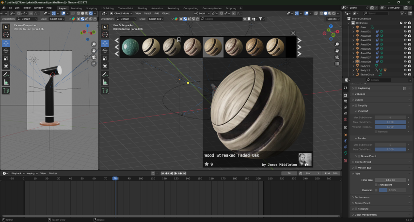
- I used Blende kits add-in for adding texture
- Go the link and download the zip file and follow the instruction to install the add in to blender
Link : BlenderKit | FREE 3D models, textures and other Blender assets
- Then from the top search bar select the texture drand and drop to the body where you want to add the texture
- After this add lighting in the environment
I faced a problem here, I was not able to add any type of light except sun so I had to use multiple sun as my light source
- Then i place all the light source around in the 3D space and adjusted the brightness to attain a desired out put
- Also from the top right section the window i made it into rendered view to check the output
- After this step i animated all the parts and keyframed it
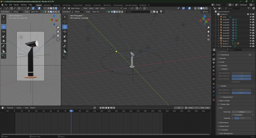
- This is the final out put
To Learn More : https://youtu.be/CBJp82tlR3M?si=dNcp54pONwGaT0bM
Video Editing
Blender
Blender comes with a built-in video sequence editor allows you to perform basic actions like video cuts and splicing, as well as more complex tasks like video masking or color grading.
The Video Editor includes:
- Live preview, luma waveform, chroma vector scope and histogram displays.
- Audio mixing, syncing, scrubbing and waveform visualization.
- Up to 32 slots for adding video, images, audio, scenes, masks and effects.
- Speed control, adjustment layers, transitions, keyframes, filters and more!
Here my idea was to make a simple video that showcases the workspace in blender and the final out put
- First open the blender video editing tool
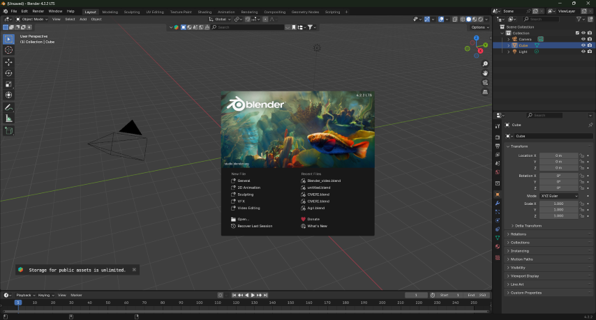
- Then from the left window open the video needed to be edited drag and drop the videos into the work space
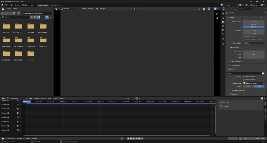
- Then adjust the number of frames to be rendered from the right top window
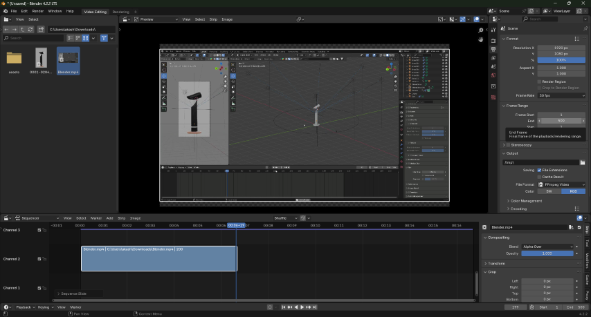
- Then drag and drop the the second video
- Also add the fade for the videos by right clicking on the video from the sequence tool bar
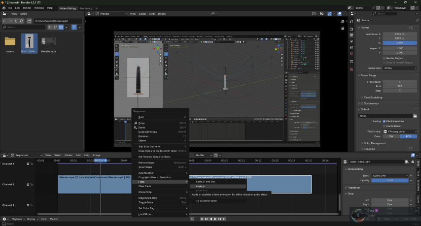
- Then add text and move the location and place the text in the correct location
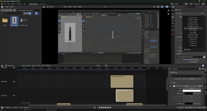
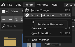
- Then from the top left corner Click on the Render Animation
- Final Output
To learn more : https://youtu.be/yh7YPabqeDk?si=aO2rEcz8bgdrBeYm
Clipchamp
Microsoft Clipchamp is an online video editor designed to make video creation easy for everyone, even for those with no prior editing experience.
The video editor allows you to combine video assets, images, and audio files together, as well as adding visual effects like text overlays, transitions, and filters. You can also add royalty-free stock videos, music, sound effects, stickers, overlays, backgrounds, and more. Easily save videos directly to your device once you've finished editing.
Here my idea was to generate a video similar to the video I created in blender
- First import the files into the Clipchamp by drag
- Ten from the left toolbar dropping from your file
- Then place the the video on the sequence tool bar and adjust the size of the video size
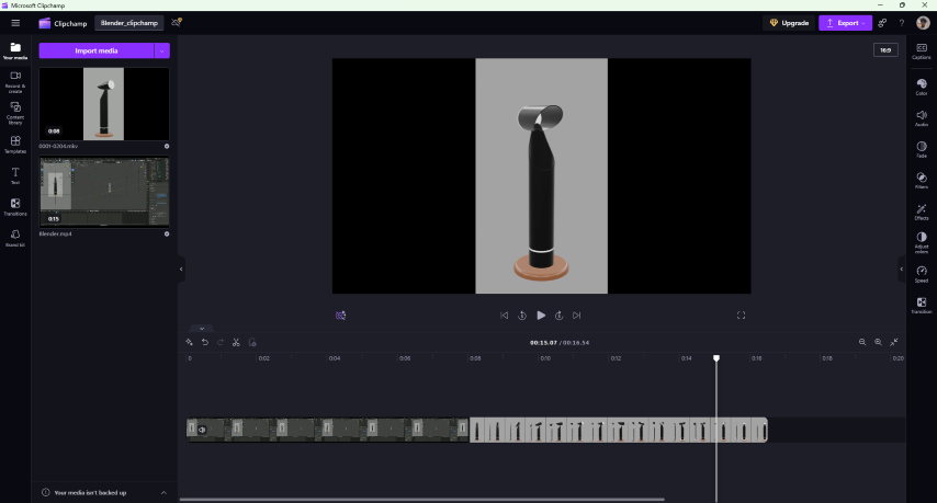
- Then from the left tool bar drag and drop type of text
- In the sequence section add a transition in between the videos
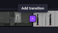
- Edit the text and set the location
- Final output
Compression
Microsoft PowerToys Image Compression
Microsoft PowerToys is a set of freeware (later open source) system utilities designed for power users developed by Microsoft for use on the Windows operating system. These programs add or change features to maximize productivity or add more customization. PowerToys are available for Windows 95, Windows XP, Windows 10, and Windows 11 (and explicitly not compatible with Windows Vista, 7, 8, or 8.1). The PowerToys for Windows 10 and Windows 11 are free and open-source software licensed under the MIT License and hosted on GitHub.
Link : https://docs.microsoft.com/en-us/windows/powertoys/install
- Fist step is to go to file manager select the files that needed to be compressed
- Then right click and click the “Resize with Image Resizer”
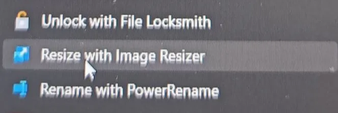
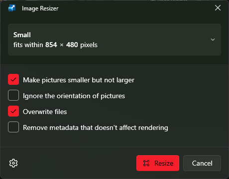
- The in the size set to desired size
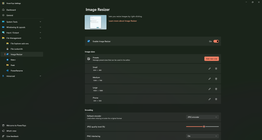
- Then go to settings then in Encoder section reduce the quality size
- Then press the Resize button
Free Converter Video Compression
FreeConvert is an online file converter. So it works on Windows, Mac, Linux, or any mobile device. All major browsers are supported. Simply upload a file and select a target format. Here it is also possible to compress videos
Link : File Converter - FreeConvert.com
- Fist go to the websit
- Then click on the button “choose Files” then select all the video files that needed to be compressed
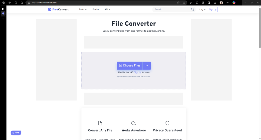
- Then press the compress button
- Then download the files
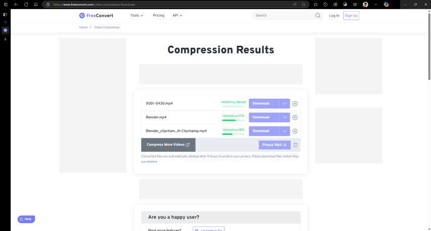
- Then the files will be downloaded to the your local drive
Conclusion
This week was a challenging and very interesting, but it was a lot of fun and i have successfully completed the all the tasks and was able to explore may softwares and tools
