Week 15
System Integration
Design and document the system integration for your final project
Features of project
My project is a simple indore delivery robot that can be used to deliver food or drinks or any other item to a user in an office environment.I contains a container that can hold the item that needs to be delivered. It would have an obstacle detection sensor that would detect if there is an obstacle in the way of the robot. It would also have two matrix display that would replicate an eye and it can be used to display some simple emotions or status of robot. The inside of the container would be illuminated using a LED strip. The robot would be controlled using a remote control and it would have a simple door mechanism that would open the container when the robot reaches the user.
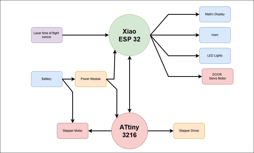
Block Diagram
The block diagram of the project is shown below. The block diagram shows the different components of the project and how they are connected to each other.
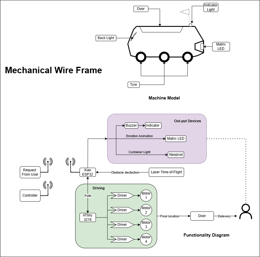
Wire Frame
The wire frame of the project is shown below. The wire frame shows the basic structure of the robot i the mechanical model section & in the functionality diagram shows how the robot works and how it interacts with its surrounds and with the user
The robot will be controlled wirelessly using a remote control or using a web interface the main brain of the robot will be a Xiao esp32 and the high power section will be controlled by a Xaio RP2040 where the motors are connected to.
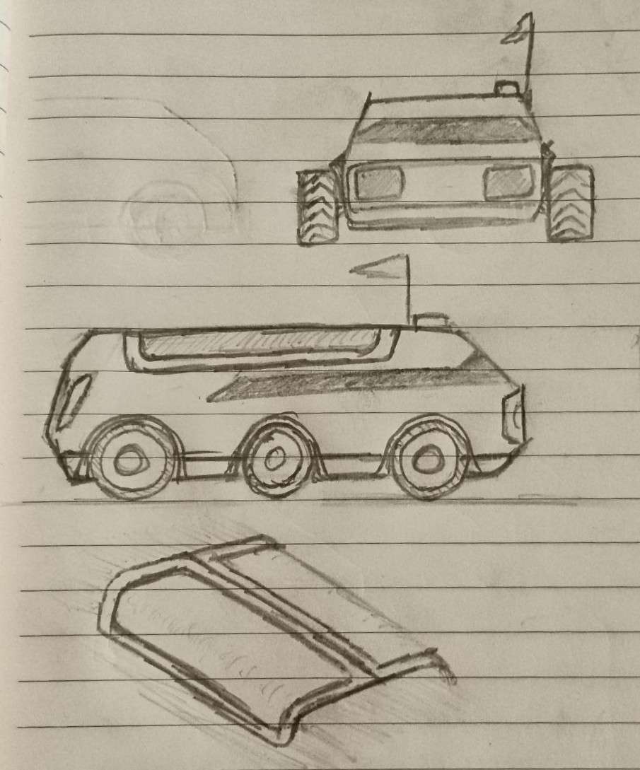
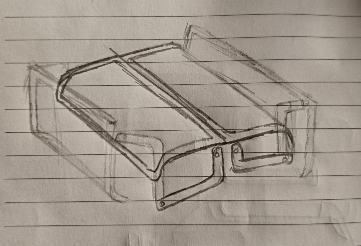
Sketches
The sketches of the project are shown below. The sketches show the different views of the robot and how it looks like from different angles, I have also shown the isometric view of how the door of the robt should look like
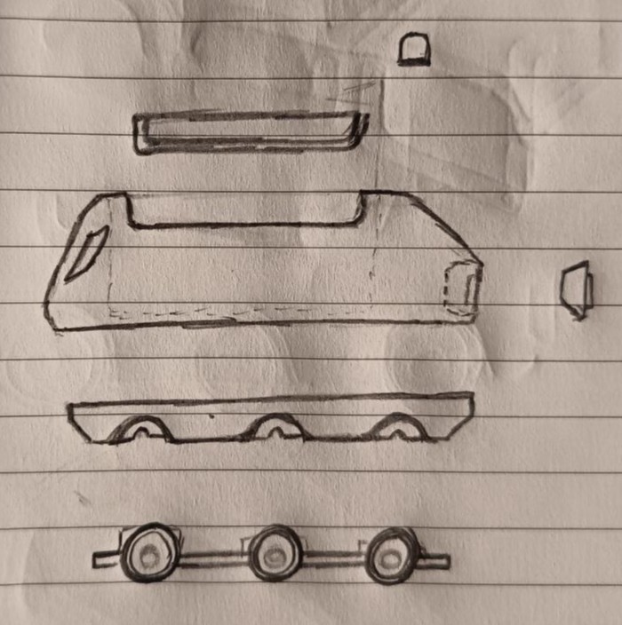
Exploded view
The exploded view of the project is shown below. The exploded view shows the different components of the robot and how they are connected to each other. The exploded view also shows the different parts of the robot and how they are assembled together.
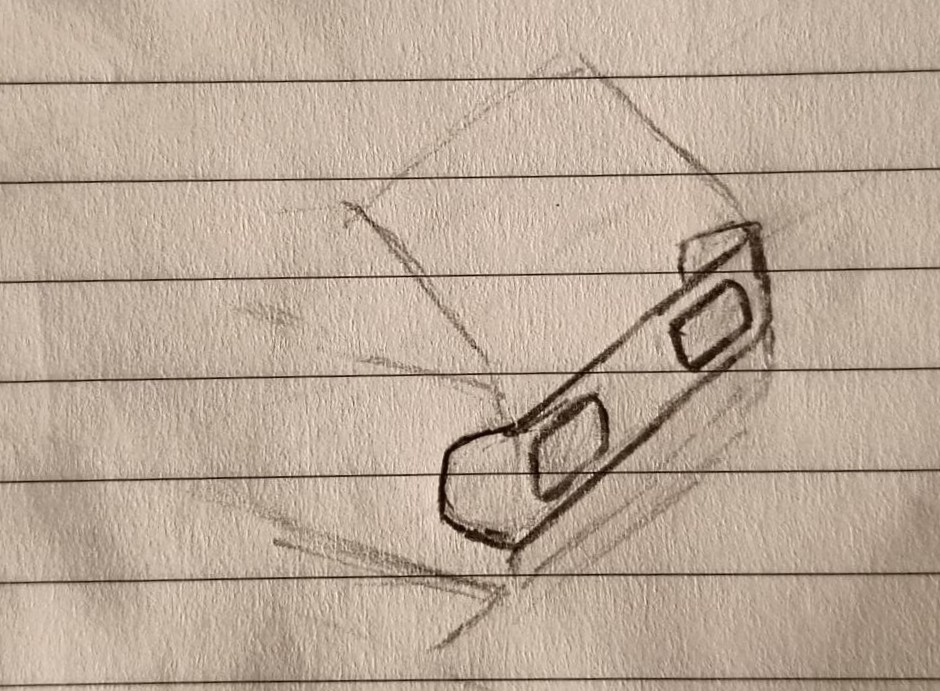
Door Mechanism
The door mechanism of the project is shown below. her i have shown the basic structure of the door mechanism and how i am planning to do it using a servo motor.
Front Section
The front section of the project is shown below. The front display shows the different emotions of the robot and how it looks like from different angles, I have also shown the isometric view of how the Front section should look like. it will have the led matrix display and the obstacle detection sensor and it would be made by bending an tinted acrylic sheet.
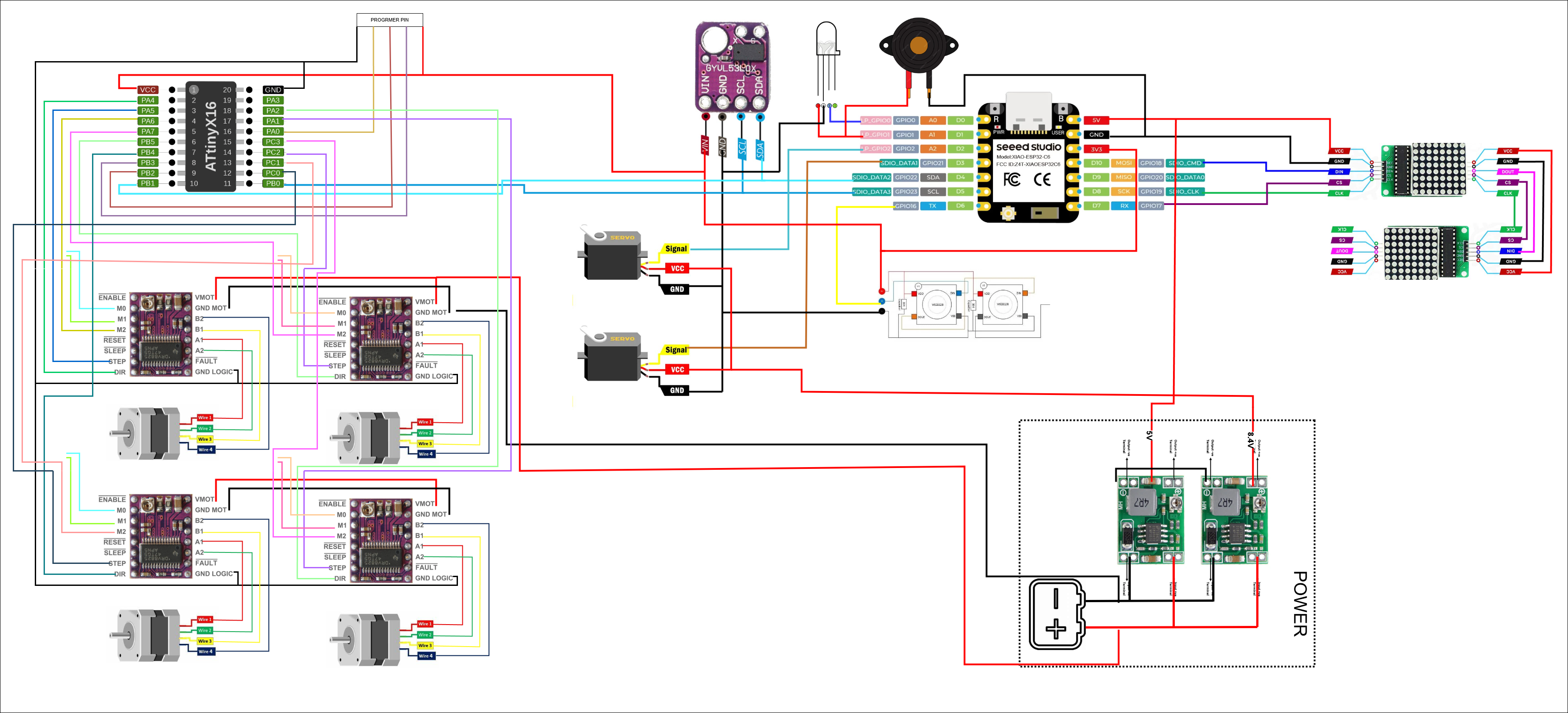
Circuit Model
The communication protocol between board is I2C there is a board for motor control a separate board for LED controls and a main board as the master module. The matrix LED board and the laser time of flight sensor will be directly connected to the main board.
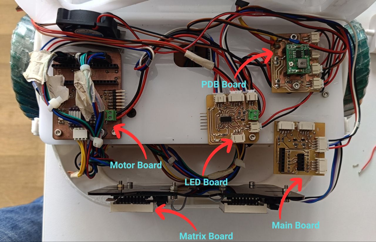
Electronic placement
The NeoPixel LED strip will be fixed onto an acrylic panel and mounted to the body using screws. The neon LED will be attached using double-sided tape. The electronic boards will be mounted on the front section of the robot's base using spacers. Additionally, a separate access door will be provided to allow easy connection, tweaking, and debugging of the internal components.I am planing to use wire organizers to route the wires and cables properly so that it would be easy to troubleshoot and debug the robot. The main board will be mounted on the top of the base and the motor control board will be mounted on the bottom of the base. The LED control board will be mounted on the front section of the robot's base.
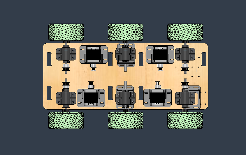
Base Arrangement
The base arrangement of the project is shown below.The base consists of the 4 stepper motor and these are connected to the wheels through belt and 3D printed pulley the wheels are mounted on the base using 3D printed brackets which has two bearings to support the wheels.And the stepper motors are connected to the main board using a 3D printed bracket.
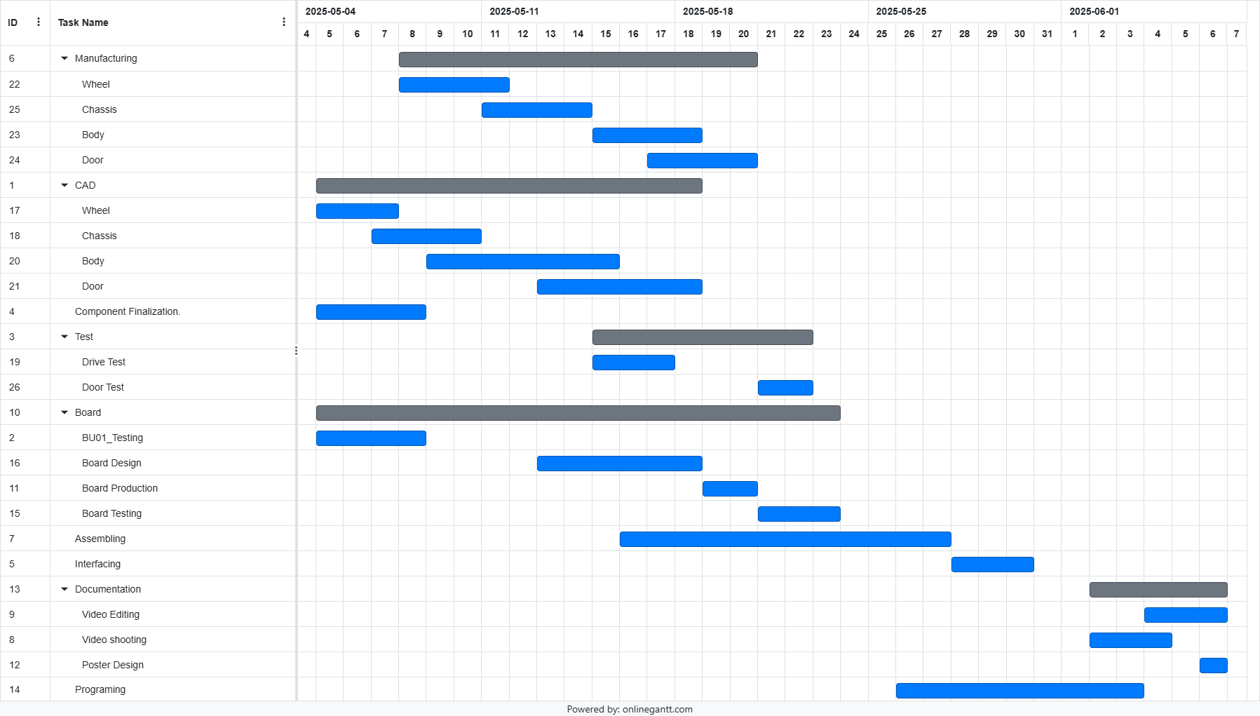
Schedule
The schedule is made using a Gantt chart and it shows the different tasks that need to be done and the time required to complete each task. The schedule also shows the different milestones of the project and the time required to complete each milestone.
Challenges
- Mechanical-Electrical Conflicts : Since i am designing the body of the robot first while i am designing i have to make sure there is enough space all the electronic components and about the place met of all the electronic boards
- Tolerance & Assembly : Since i would be using multiple methods for the manufacturing i should make sure that the components are compatible with each other and that the assembly is done correctly.
- DFX Principles : Also while designing i should be making sure that the pats are designed in such a way that it can be easily manufactured using the a processes and machineries available here in super ab lab and also i can be replicated in other labs
- Thermal Management : Since i am using stepper motors and drivers for these motors it should have proper thermal management so that it can reduce the possibility of over heating of the motors and the drivers
- Connector & Cable :The cables should be provided routing paths so that it is properly organized and the cables should be provided with proper connectors which can be easily disconnected and connected so that it would be easy to trouble shoot and debug. JST connectors will be used in most of the places so that it can be easily disconnected and connected
- Cost Efficiency: The Design should be done in such a way that the material usage is less and where ever possible cheaper processes should be used.
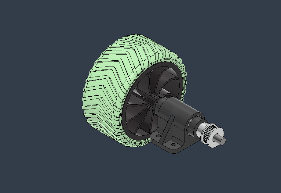
Designs
This is the design of the wheels ,wheel hub , stoppers etc for the wheel mechanism, The pules were also designed to suit the requirements
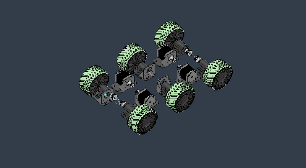
This is the placement of the wheels motors and components of the driving part.
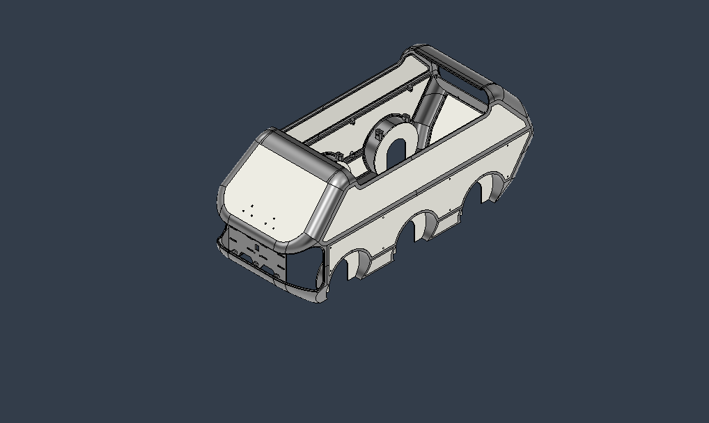
This is the design of the body which have to be 3D printed and the flat surfaces have to be laser cut from the 2 mm acrylic.
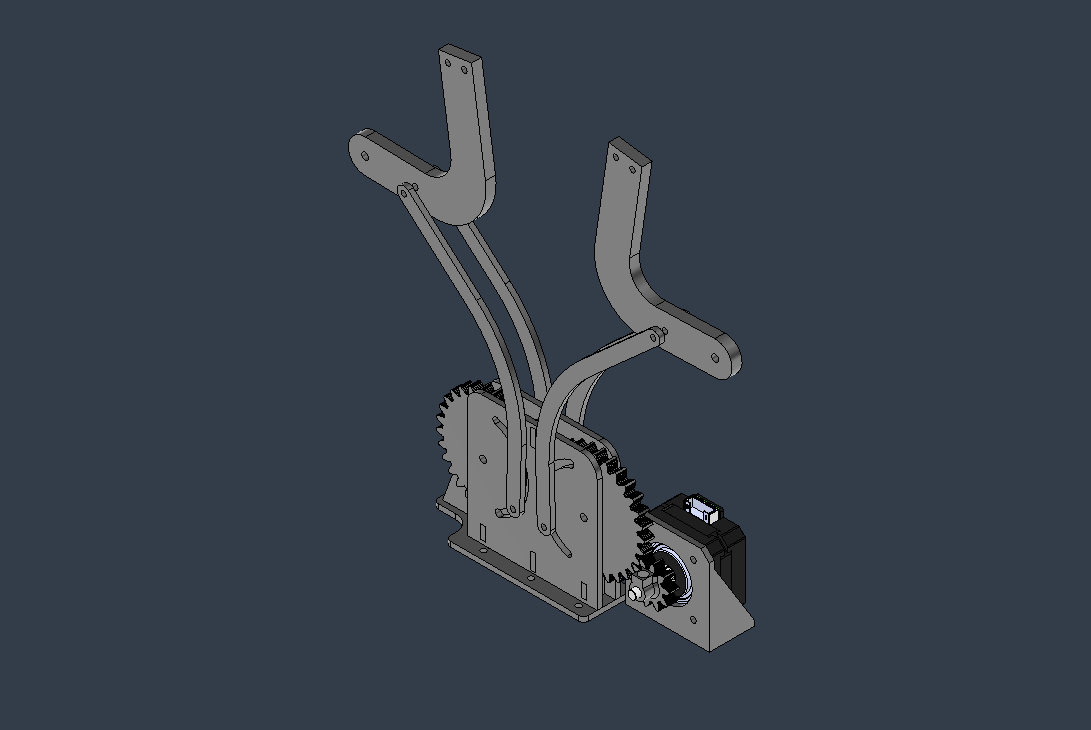
This is the design of door mechanism that have to be cut from the acrylic and the mounts for the stepper will be 3D printed and the the gear that is mounted to the stepper will also be 3D printed.
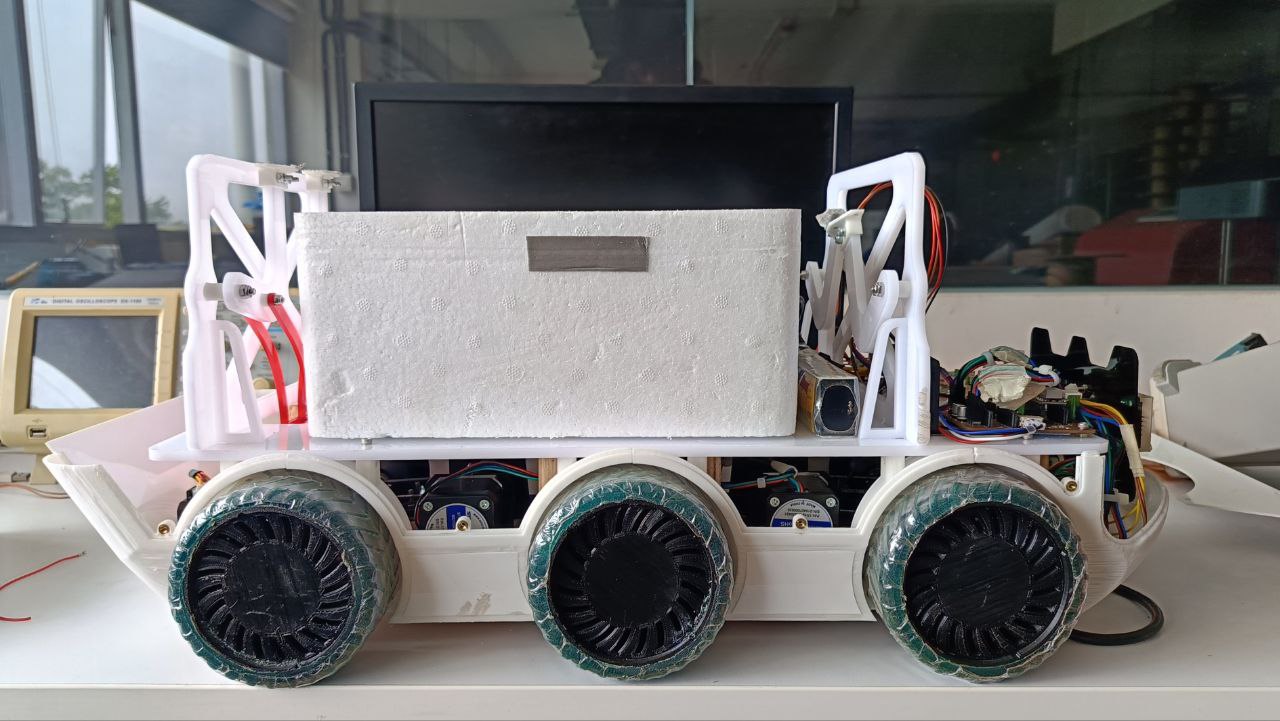
This is the side view of the robot after all the system integration.
Conclusion
After doing the system integration i got a basic idea of the time needed to complete the project.And what should be given priority and what should be done first.