Week 13
Molding and Casting
This weeks Assignment is to design a mold around the process you'll be using and produce it with a smooth surface finish that does not show the production process towpaths and use it to cast parts
Group Assignments
Group Assignment is to review the safety data sheets for each of your molding and casting materials,then make and compare test casts with each of them compare mold making processes.
Link : week 13 Group Assignment
3D Print and Molding
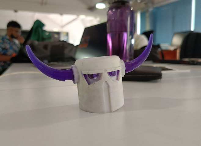
For this week my plan was to design and mold this character from clash of clans so i wanted the make the whole character but due to the time constraints I decided to make only the head. My plan was to design a 3D print that can be taken from the printing bead and resin can be poured into the mold and then after curing the pats that cover the hond and the eyes can be removed.

Design & printing
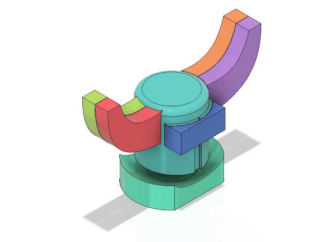
For this I started by designing the helmet section of the character then i moved to designing the hounds which i designed using the loft tool, then i moved to designing the eyes. then the body was done after that I designed the removable parts of the hounds and the eyes, I used a test jig that was printed in the 3D printed week and used the off-set from the test jig to design the removable parts.
This is how the me molding is supposed to work.After the resin is poured in the mold it will be cured and then the parts can be removed. And in the designed with pins to hold the parts in place. But that was not a good idea as you can see it later in the document.
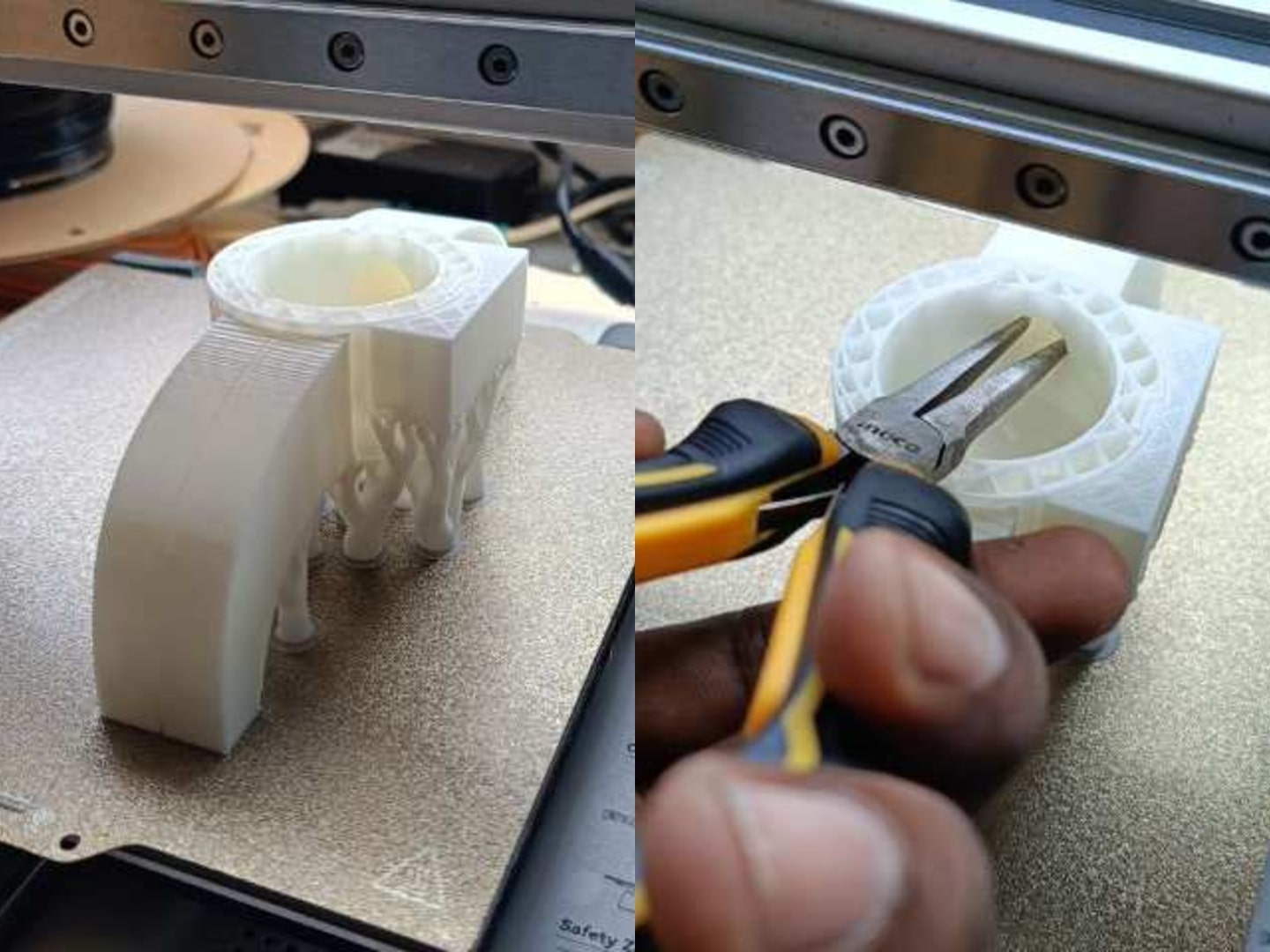
Here I used tree supports so that it can be easily removed. And after the print is partially printed the supports from inside the hounds and eyes and the print have to be completed. Be careful not to tho break the print from the bed. Then i proceeded for printing which almost took 4 hours to complete.
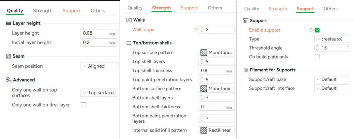
These are the parameters I used for printing with the Bambu Lab 3D printer: I set the wall loop count to 3 for stronger outer walls, enabled tree supports for efficient support structure, and used a layer height of 0.08 mm to achieve high-quality print details.
This is t he final output of the print. Try I used the highest resolution for the print so that the parts can be easily removed and the surface finish is smooth.If possible try to use a separate finishing process but in my case my mold is only removed after the molding is done.
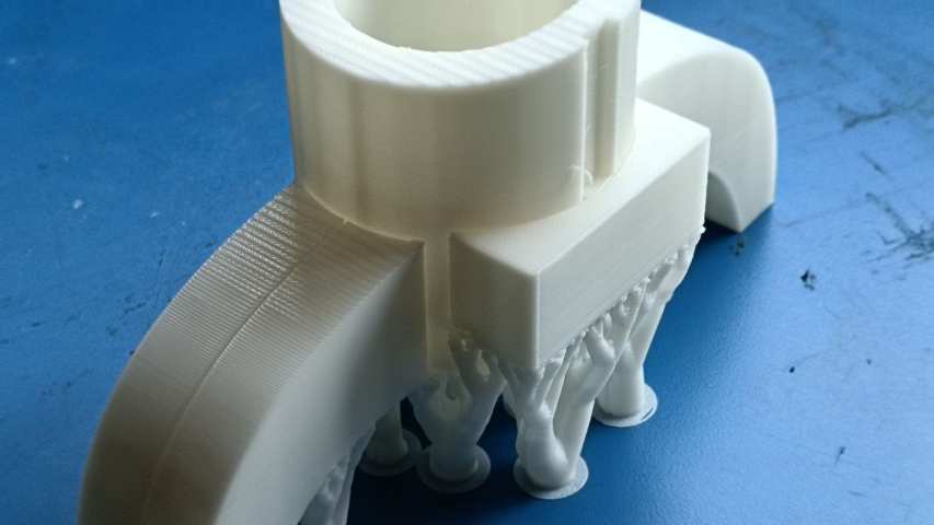
Here it is visible that the parts have enough clearance so that the mould can be easily removed and while printing the layers does not get joined. this can also act as vending holes so that the heat can dissipated easily.
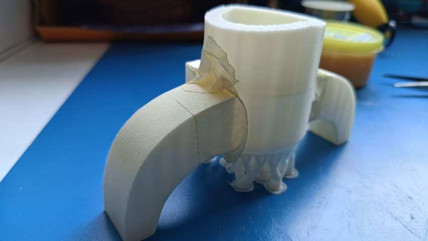
To prevent the resin from leaking out I added some tape in the area where there is a gap. I had also removed some supports so that the tape can be applied properly.
Molding
Here I am using Aditya Ultra Clear Cast Epoxy – 37 which have an A & B ratio of 2:1 with a curing time of almost 5 to 6 hours.
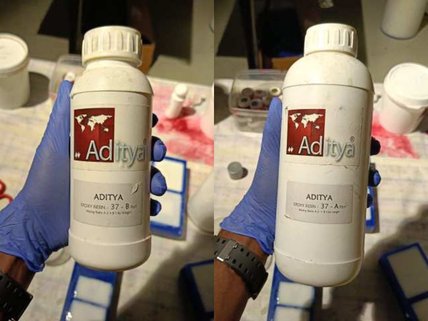
Website Link: www.adityabirlachemicals.com
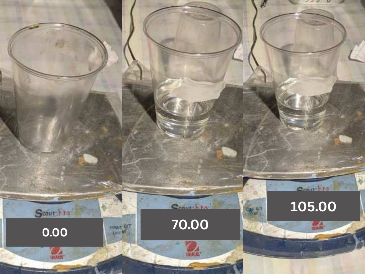
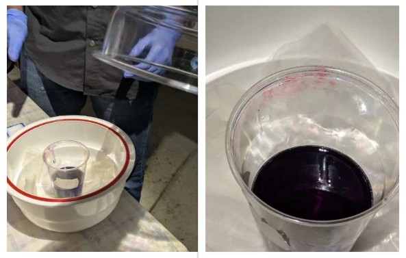
First I measured the volume of the cast using the water. And then I used the same volume of the resin to be poured in the mold. I used a measuring cup to measure the volume of the resin. And then I measured the weight of the resin and depending on the weight i poured the next portion of the resin.
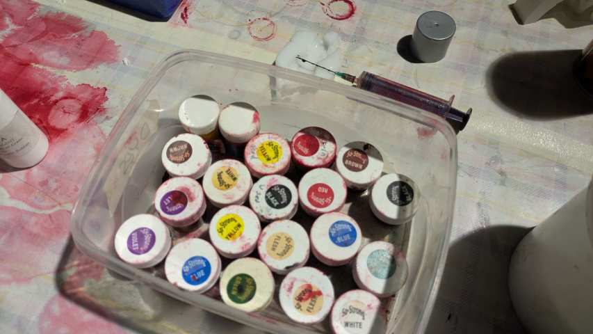
For my design I wanted to use a coloured resin so that the color of the character can be seen clearly. so from the colors we had in inventory I chose the colours that I wanted to use.
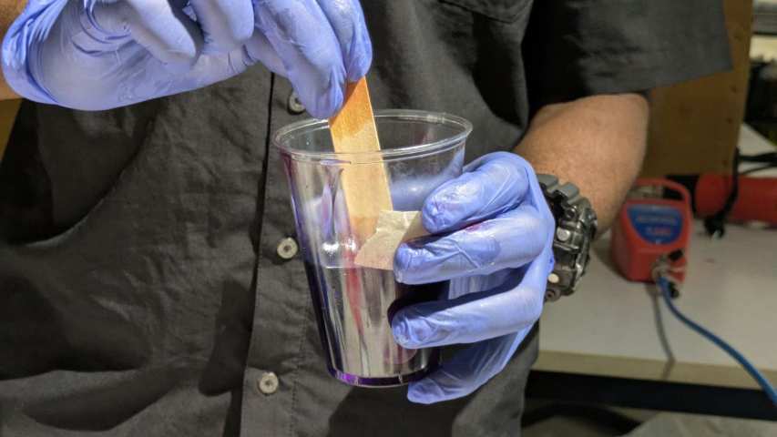
I used a cup to mix the resin and the hardener. I used a stick to mix the resin and the hardener. I mixed it thoroughly so that the resin is properly mixed with the hardener,I made sure to reduce the air bubbles in the mixture.
Then I used the vacuum pump to remove the air bubbles from the mixture.
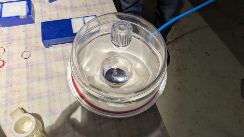
Here it is visible the air bubbles being removed when the vacuum pump is turned on.
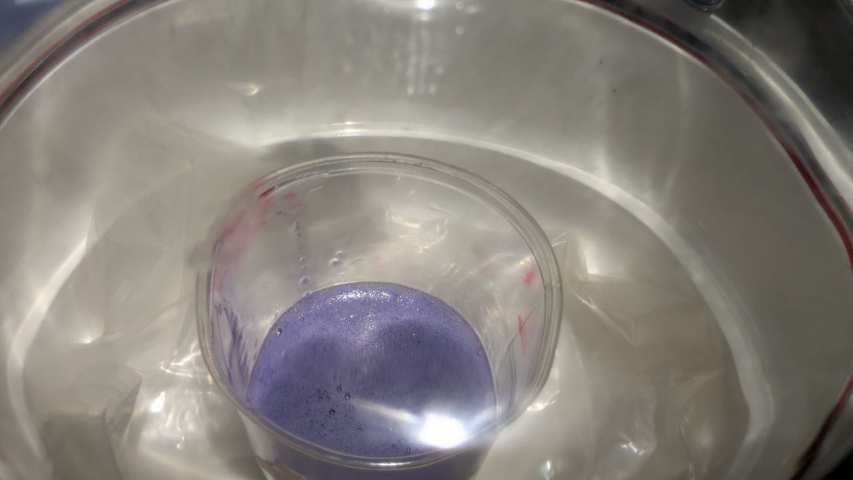
Then I opened the vacuum container and Inspected the th resin mixture. And made sure the max about of air bubbles are removed.
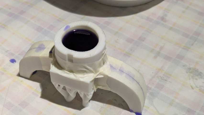
Then I poured the resin in the mold and made sure that the resin is properly poured in the mold. I used a stick to remove the air bubbles from the mold and also to guide the resin properly into the mold.
After pouring i noticed there were some leakages in the mold so i used the tape to seal the leaks
And I used it for curing overnight so that the resin can get cured.
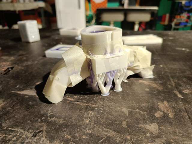
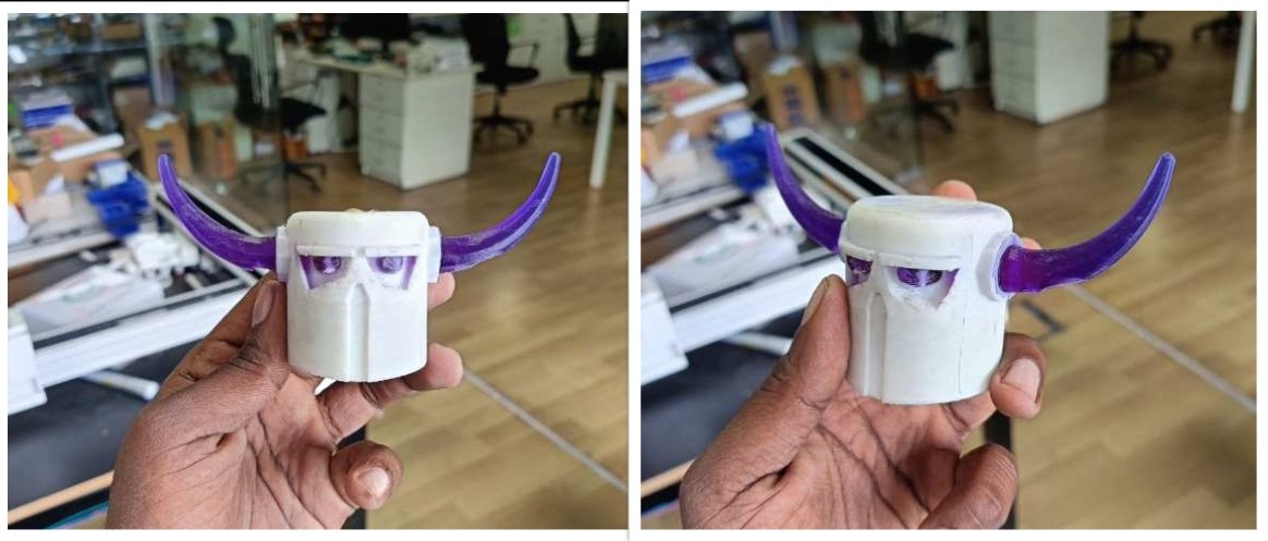
Then next day i removed all the tape to open the mould but noticed that the resin resin has over flowed and filled all the gaps in the mould this made it very difficult to remove the mould even though i had sprayed the mould release spray.
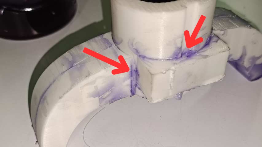
This is before removing the the removable parts from the mould.
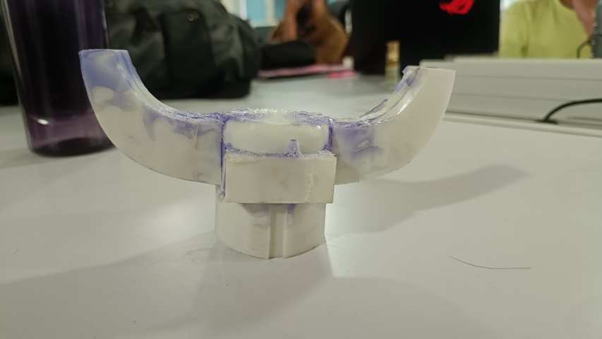
Then I removed the removable parts from the mould which was the hardest part from the I had to apply a lot of force to remove then , Some parts were even harder to remove so i had to use heat gun to heat some part and i had to pocket it with a screwdriver to remove.
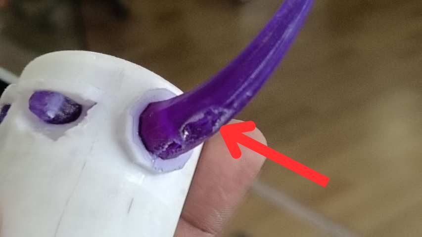
Due to a lot of force the part was a bit scratched and had a lot of marks on it.
Issues
The main issue was the leakage of the resin from the mould and the over flow of the resin from the mould. I had to use a lot of force to remove the removable parts from the mould.
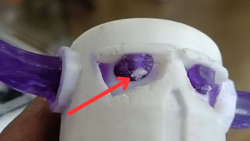
The second issue was a small 3D print support was not removed properly so it got stuck in the resin.
The third issue was the resin was leaking from som places this lead to air pockets in the final output.
CNC milling and casting
For making a stand for the character I used the CNC milling machine to mill the mold. I designed a stand that can be used to hold the character which was to be made using cnc milling and can be molded.
Fist I designed the part in fuion 360 and itriedto make the design as simple as possible so that it could be easily machined.
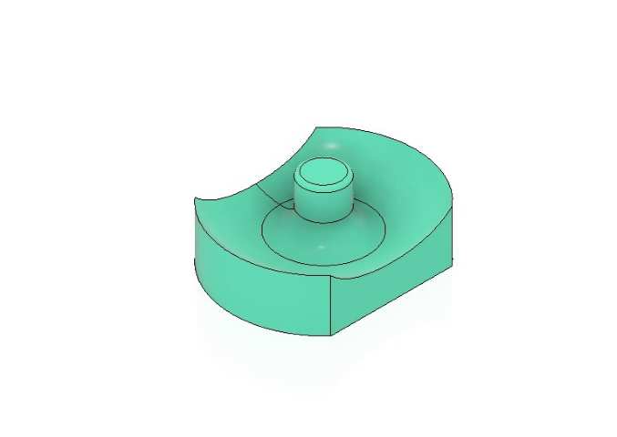
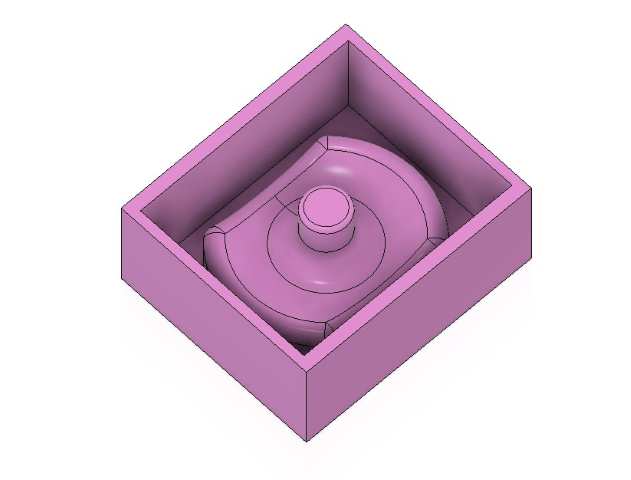
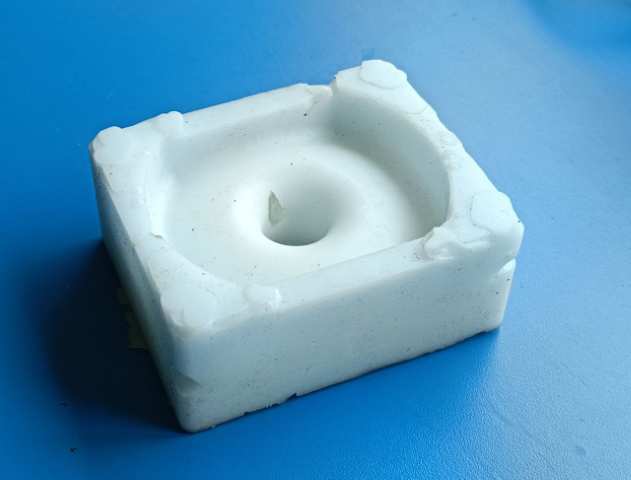
Then I made the design for the wax mold this is to first make a silicon mould and that silicon mold can be used to replicate the final output multiplies times.
Milling
TRAK DPM RX2
AI Prompt :Give a small brief about TRAK DPM RX2 in paragraph
The TRAK DPM RX2 is a high-performance CNC bed mill designed to meet the demands of modern toolrooms and small production environments. It blends the tactile control of a manual knee mill with the power and precision of full 3-axis CNC machining. With its integrated ProtoTRAK RMX CNC control, the RX2 allows for flexible operation—users can switch between manual, 2-axis CNC, and full 3-axis CNC control based on the complexity of the task. This makes it an ideal machine for machinists who need both traditional feel and digital precision. The RX2 features a robust construction with a table measuring 49" x 9", and travel ranges of 31" on the X-axis, 16" on the Y-axis, and up to 26.75" on the Z-axis (with way covers removed). The spindle is powered by a 3 HP continuous-duty motor and offers a wide speed range from 40 to 5,000 RPM, accommodating a variety of cutting applications. The machine also includes a 5" quill travel, R8 spindle taper, and precision-ground ballscrews for reliable performance. Designed with both ergonomics and productivity in mind, the TRAK DPM RX2 includes real handwheels for manual control, programmable spindle speeds, and rigid tapping functionality. The bed mill's solid ram construction and Turcite®-coated slideways ensure durability and smooth movement during heavy cutting operations. Overall, the RX2 is a versatile and dependable milling solution for shops requiring both conventional and CNC capabilities.
CAM
For this i am using fusion360 for design and cam so first i went into the machining interface of fusion360 and selected the milling option
Then i fund the tool library for all the tools available in super fab lab kochi.Then from the top tool bar on the right side i went into to the Tool library section.
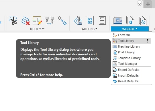
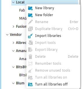
Then from the window that opened went into the left sectioni went to the local section
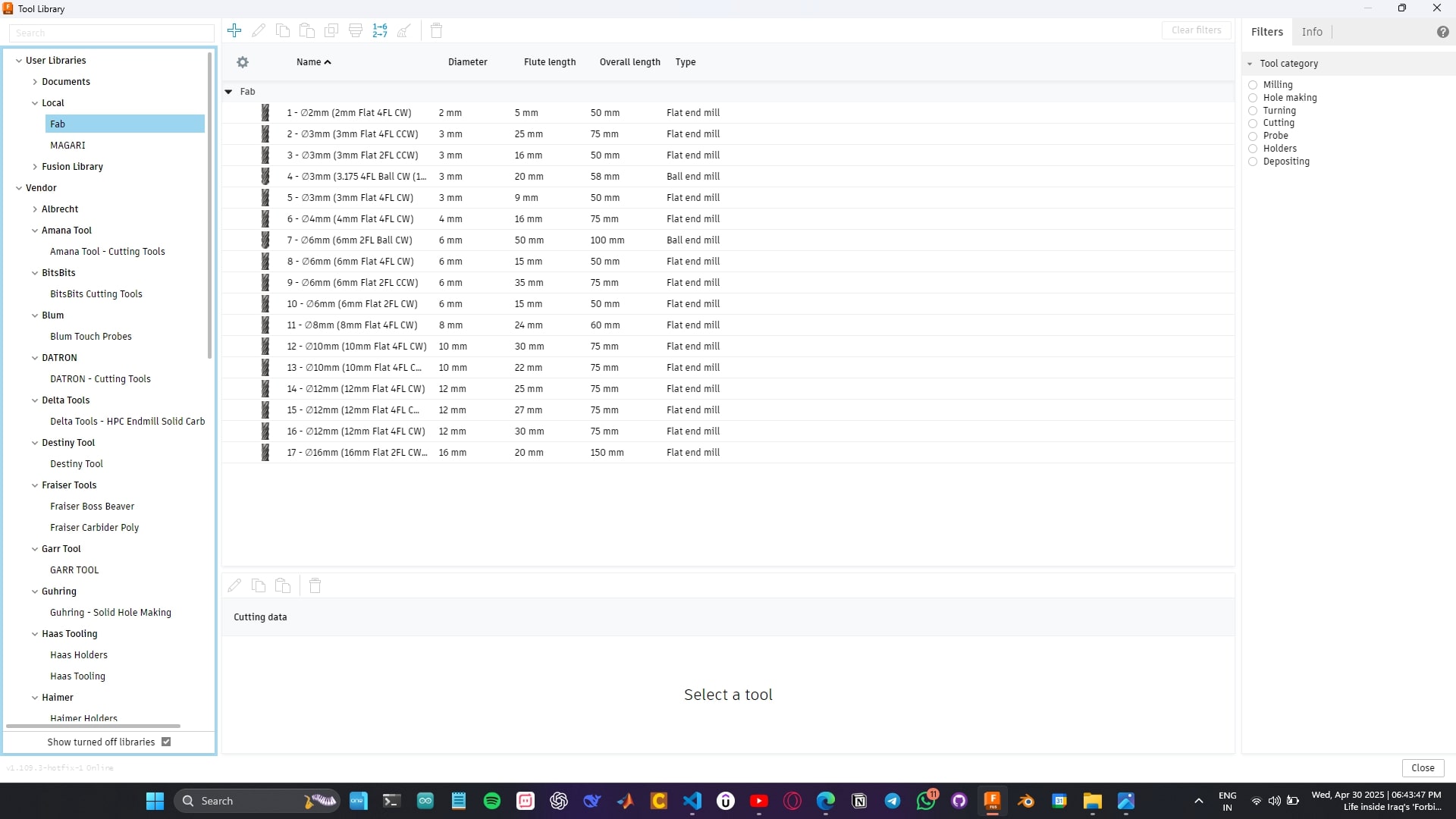
Then right click on the local section and then select the new library & select the file from thr local folder and this will be added to the tool library
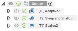
Then i made multiple operations for the milling process I used Adaptive,steep and shallow & a scallop operation for the milling process.
depending on the machine i had added the rap speed and feed rate etc..
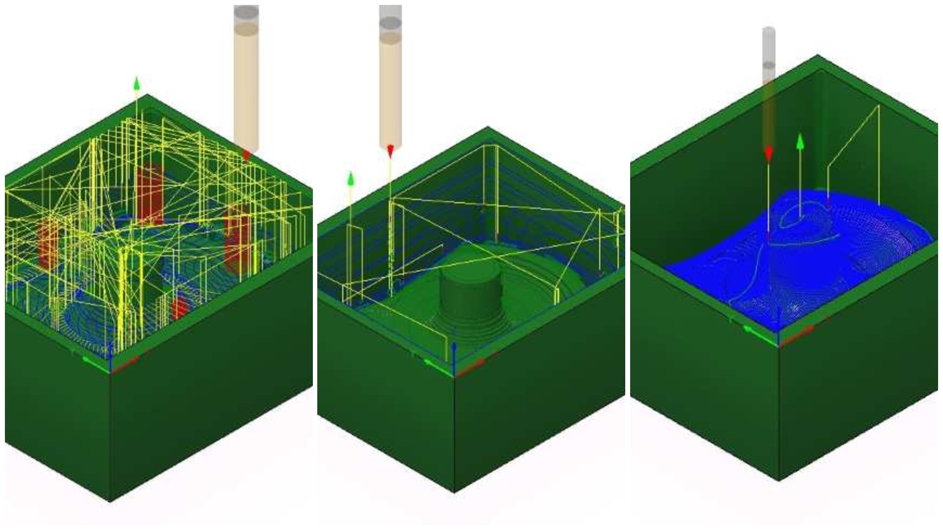
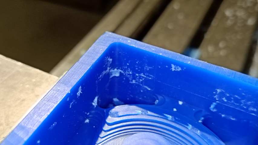
Then i proceeded for machining and i went through one by one for the first step i machine the adaptive tool path using the 6mm flat end mill
This is the output after the first step
Then i proceeded to the steep and shallow operation but in the middle tool brock i was used the 3mm flat end mill
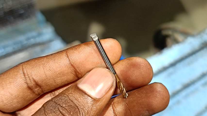
The tool brock because the tool was removing a lot of material from the side wall i had given a stock to leave of .5 mm in the previous tool path and due to this too much load was being applied to the tool which lead to the tool breaking
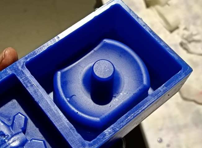
Then to overcome this issue i had to make a small edit on the design os the side walls of the mould and made it bigger so the tools pass easily
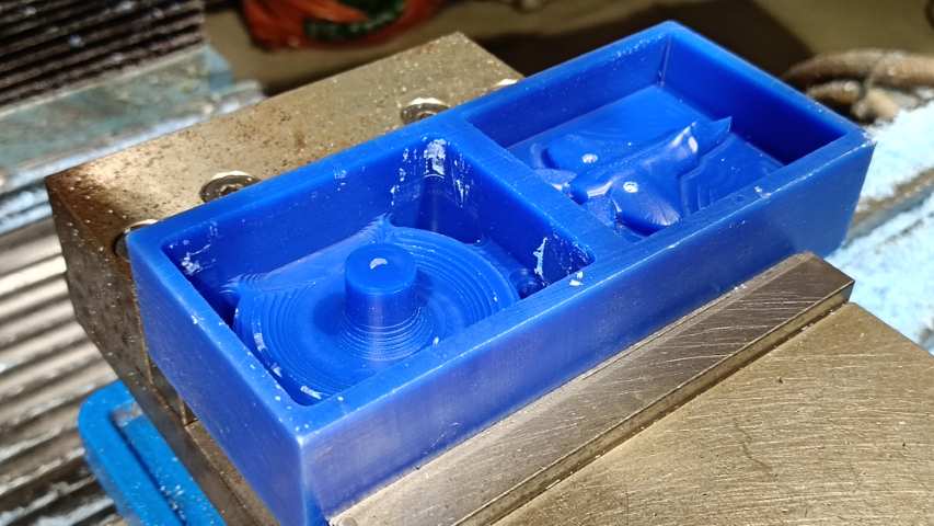
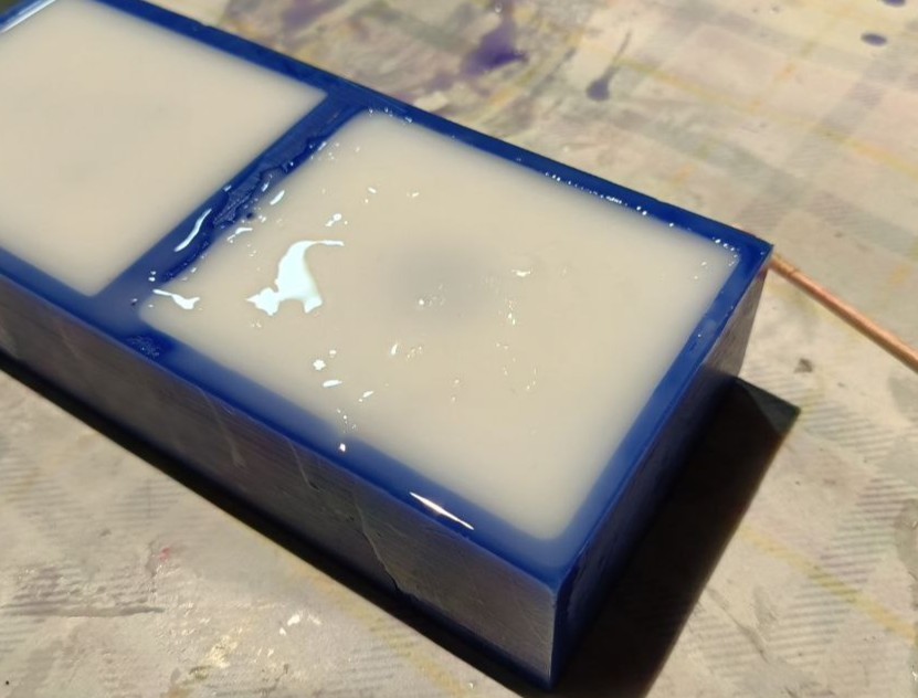
Then i proceeded to pouring the silicon resin into the mould and let it cure for almost 12 hours
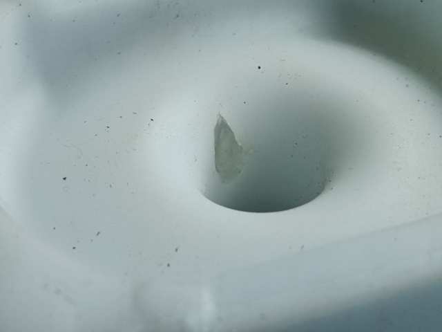
After curing i removed the silicon mould from the CNC milled part THere was a air bubble that go trapped inside this that lead to a small air gap in the mould
For solving this i had used UV glue to fill the air gap and then fixed this issue.
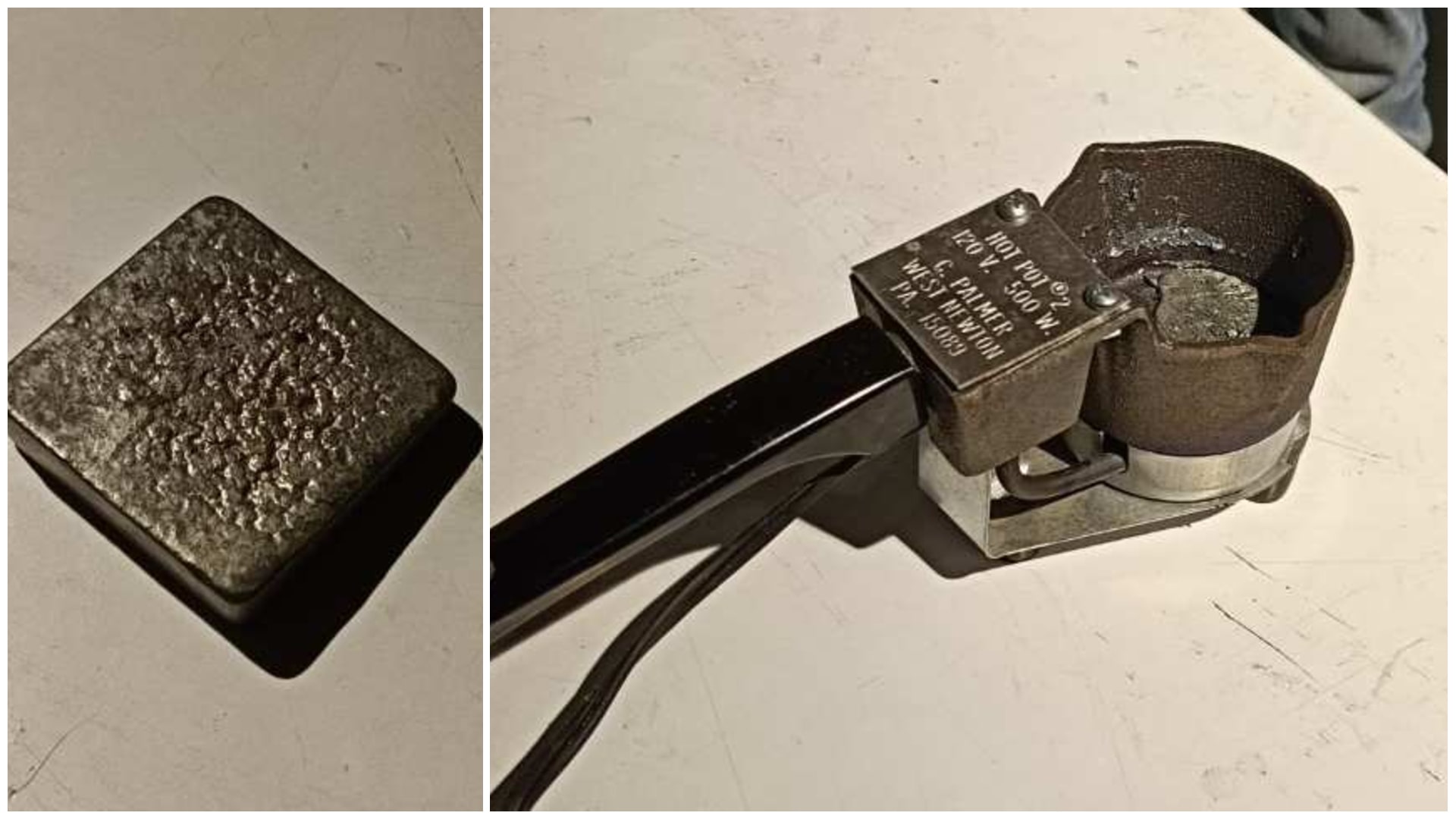
After i proceeded to the moulding bismuth in this for this i melted the poured the molten bismuth into the mold cavity and let it cure.
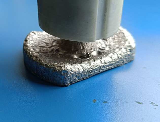
After curing i removed the mould and this is the final output of the cast i had tried shaking to remove all the bubbles but this did not work
And this is the final output after assembling everything together.
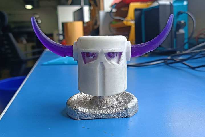
Conclusion
This week, I learned a lot through hands-on experimentation. I designed the head of the character and explored a new technique—pouring resin directly onto the model straight from the 3D print bed, without any post-processing. After curing, I was successfully able to remove the removable parts from the mold, which gave me the final output. For the base, I used bismuth. To create a mold for casting the bismuth, I first milled a mold shape and used it to make a silicone mold. Once the silicone was poured and cured, I melted the bismuth, poured it into the silicone mold, and let it cool. After everything was ready, I assembled all the parts to complete the final piece.