Week 12: Mechanical Design
➡️ View our full group documentation here.
Overview
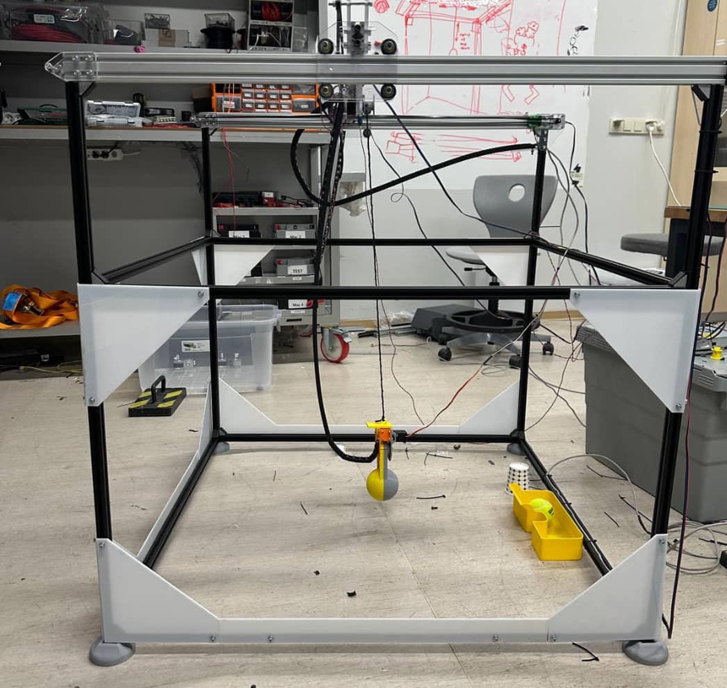
For this group project, I was responsible for the full mechanical side of the machine. I designed the CAD model, machined the polycarbonate parts on the CNC router, created and assembled the V-wheel carriage, routed GT2 belts, installed the motors, and handled wiring and cable management.
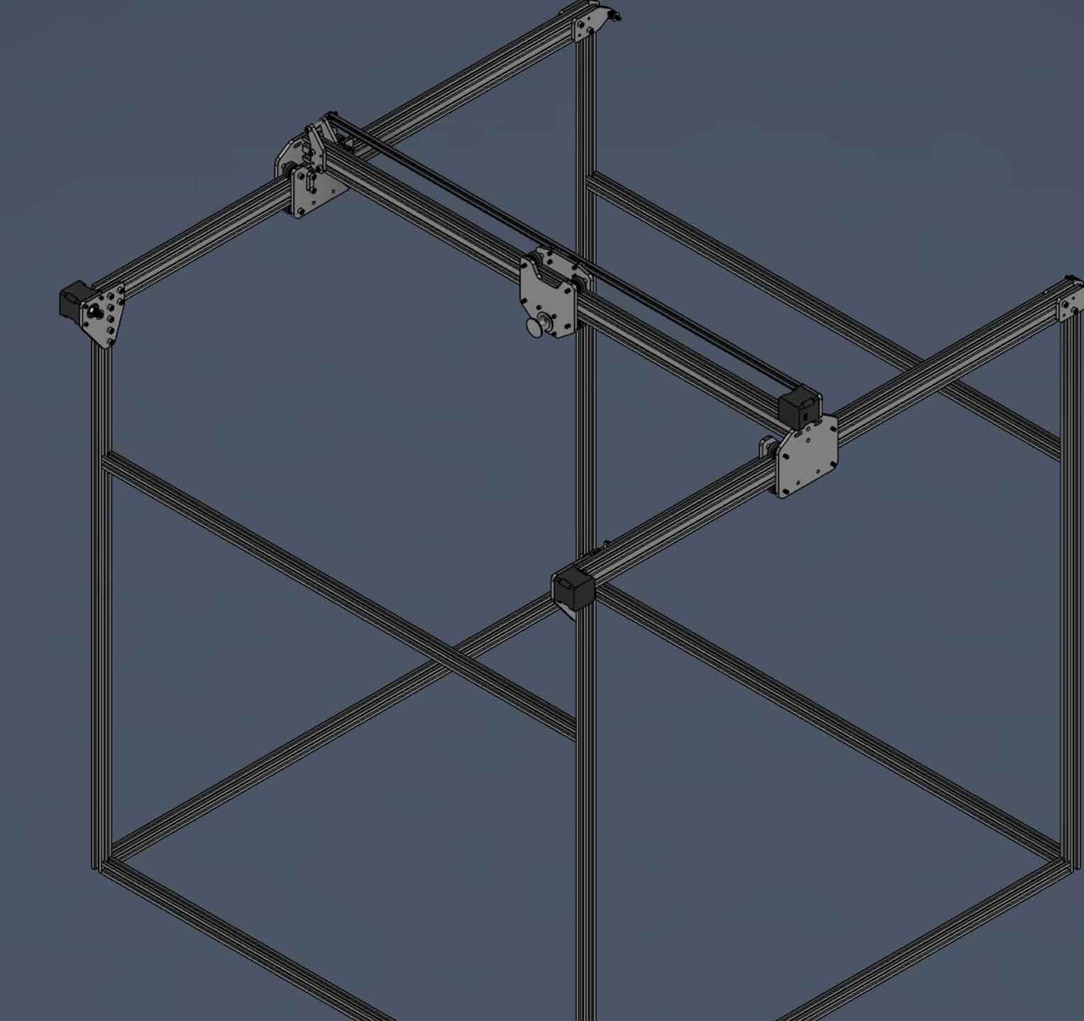
Mechanical System Architecture
I designed a motion system using V-wheels on 20x20mm aluminum extrusion rails and powered it with GT2 belts driven by NEMA 17 stepper motors.
- Linear Motion: GT2 belts + V-wheels on aluminum V-slot
- Frame: Modular Sigma aluminum profiles
- Carriage: Custom-designed and 3D printed
- Motor Mounts: 3D printed, slotted for belt tensioning
- Plates: CNC machined polycarbonate structural plates
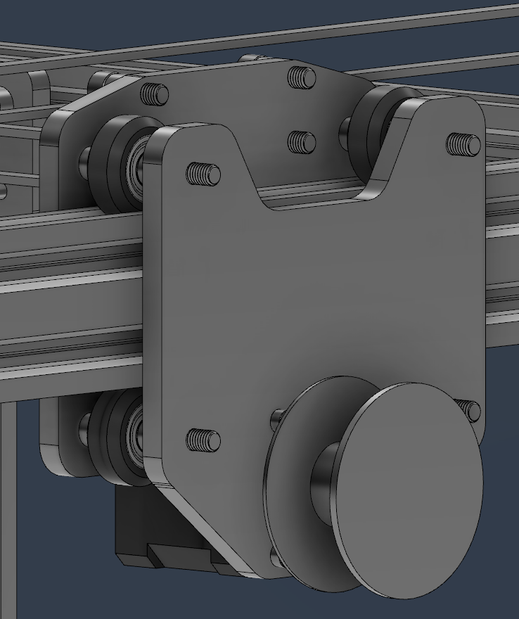
Custom V-Wheel Carriage
I designed a compact carriage that:
- Mounts on four V-wheels (two fixed, two adjustable with eccentric nuts)
- Integrates GT2 belt mounting slots
- Supports future toolhead add-ons
The part was 3D printed in PETG for strength and smooth motion.
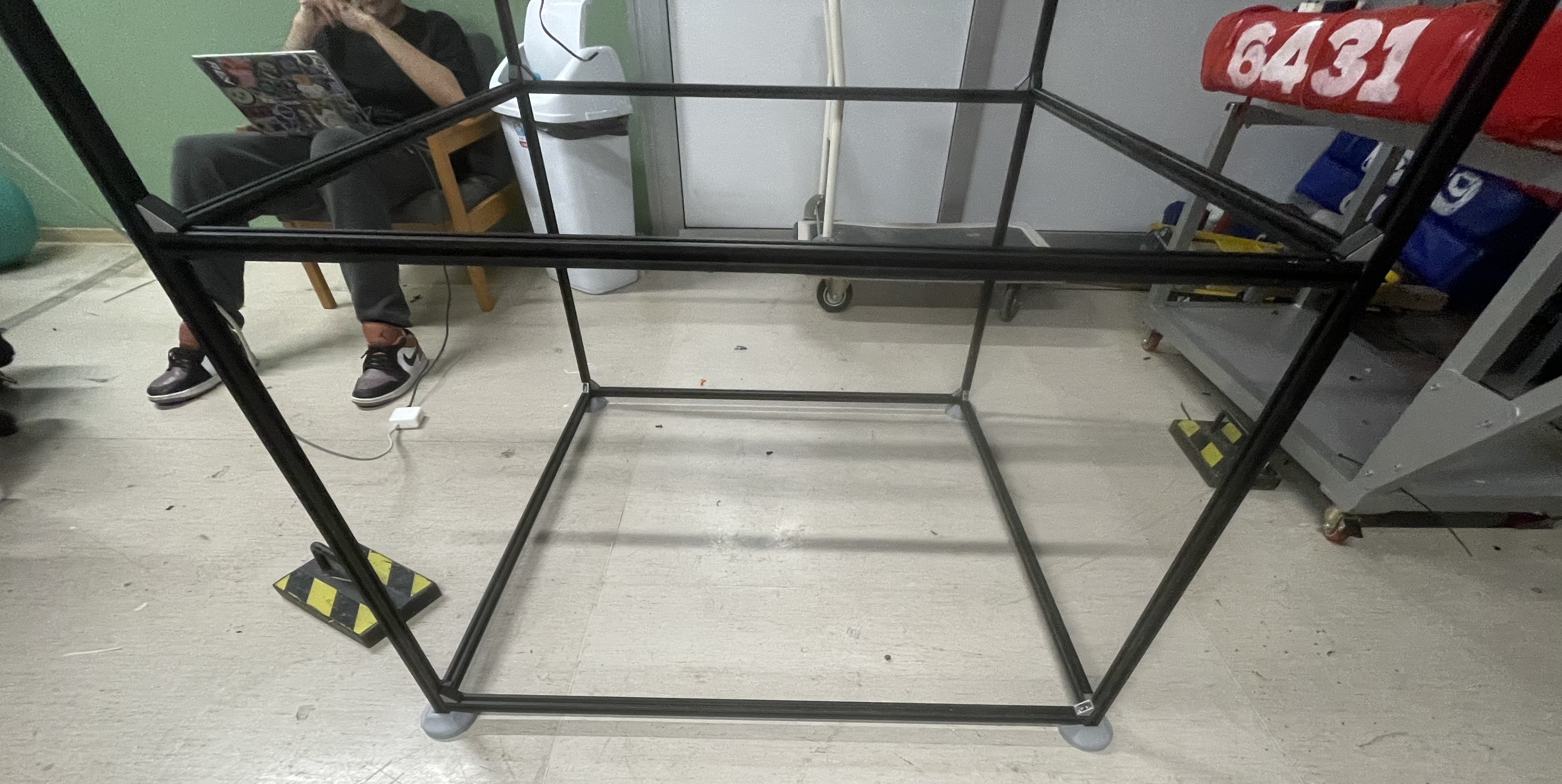
Frame and CNC-Machined Plates
I built the frame from Sigma aluminum profiles and connected them with brackets and T-nuts. I also designed and machined polycarbonate plates on our CNC router, which were used for motor mounting and structural bracing.
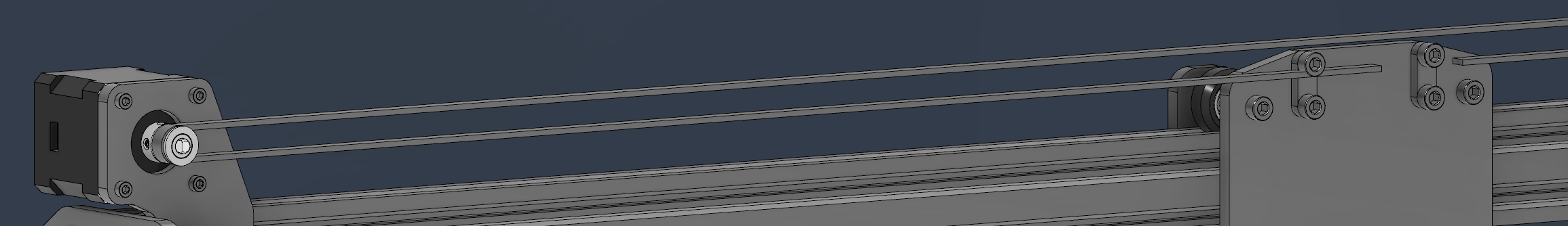
Motor System and GT2 Transmission
I mounted NEMA 17 stepper motors using slotted 3D-printed brackets and connected them to GT2 pulleys. Idler pulleys were placed at the opposite ends. I clamped the belts directly to my custom carriage design.
Manufacturing
I exported STL files from Fusion 360 for all printed parts and machined toolpaths for polycarbonate using Fusion CAM. All parts were fabricated and post-processed by me.
- 3D printed in PETG (carriage, motor brackets)
- CNC routed polycarbonate plates
- Deburred, tested, and fitted manually
Assembly and Wiring
I completed the full mechanical assembly, which included:
- Assembling the frame and installing structural plates
- Mounting V-wheels and tensioning with eccentric nuts
- Installing motors and aligning pulleys
- Routing and tensioning GT2 belts
I also handled all the electrical wiring and cable routing. I used cable channels mounted to the frame and carefully routed motor wires, labeling and organizing them before connecting everything to the control board.
I fixed an issue with uneven belt tension by adjusting the belt clamp design and reprinting the part.
Reflections
Doing all of the mechanical work from CAD to CNC and wiring helped me better understand complete machine design. I enjoyed solving practical issues like belt misalignment and routing clean cable paths. This assignment improved both my design and hands-on assembly skills.