Week 7: Computer-Controlled Machining
Assignments
Group assignment: Test runout, alignment, speeds, feeds, and toolpaths for your machine.
Individual assignment: Make something big using a CNC machine.
Idea and Design
For this week's assignment, I designed a modular structure consisting of two identical side panels and a base plate that could be press-fit together. My goal was to create a strong yet easily manufacturable design using 18 mm plywood. The design focuses on symmetry, efficient material use, and mechanical fit.
I used Fusion 360 for the entire workflow, including parametric CAD modeling, CAM setup, simulation, and toolpath generation.
Designing the Parts
CAD Process (Images f1 and f2)
In Fusion 360, I created 2D sketches for the components. The design included mounting holes, curved edges, and press-fit joints. All measurements were parametrically defined to ensure adaptability and precision.
- The side panels were dimensioned for symmetry and stability.
- Hole placements and arc radii were calculated based on intended functionality.
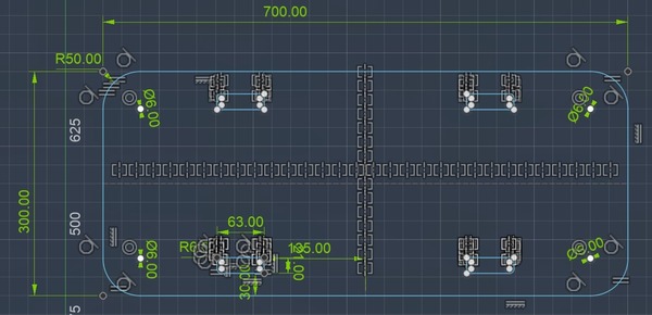
- The base plate includes rounded corners, hole arrays, and rectangular slots for interlocking tabs.
Image f1: Side panel with full dimensions
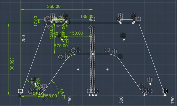
Image f2: Top view with hole pattern
Nesting and Layout
Images f3 and f4
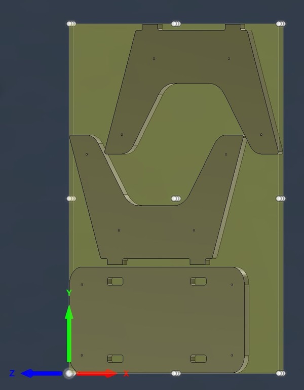
After finishing the sketches, I laid out all parts on a 600 mm x 1200 mm plywood board inside Fusion 360’s Manufacturing environment. This step ensured that the toolpaths would run within the stock boundaries.
- Parts were arranged for optimal material use and tool clearance.
- All designs respected the material's grain direction and cutting margins.
Image f3: Flat layout of components
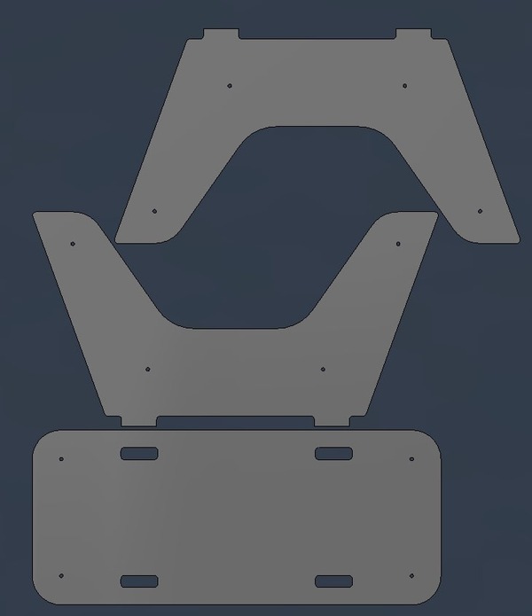
Image f4: Nested layout in stock material
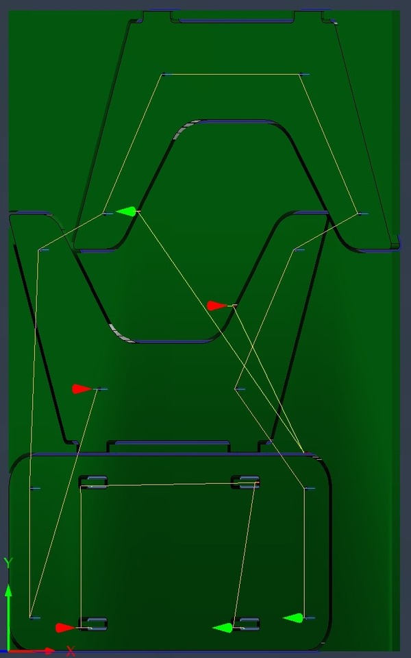
CAM and Toolpaths
Image f5
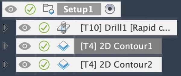
In Fusion 360’s Manufacturing workspace, I created the CAM setup with the correct stock dimensions and defined three operations:
- Drill1: For mounting holes
- 2D Contour1: For internal contours and cutouts
- 2D Contour2: For the final outer profiles
Image f5: CAM setup in Fusion 360
Tool Setup
Image f6: Drill Bit (6 mm HSS)
- Tool type: Drill
- Diameter: 6 mm
- Flute length: 80 mm
- Overall length: 130 mm
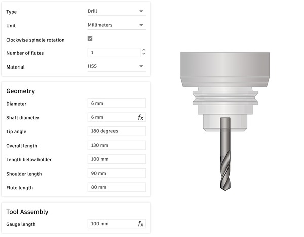
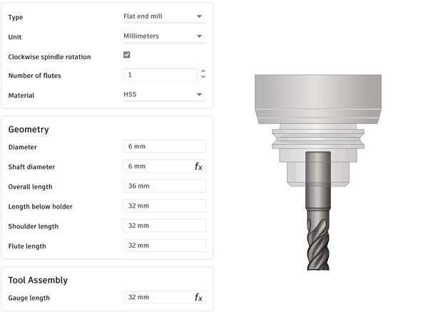
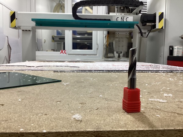
Image f7: Flat End Mill (6 mm HSS)
- Tool type: Flat end mill
- Diameter: 6 mm
- Flute length: 32 mm
- Overall length: 36 mm
Toolpath Simulation
Images f8 and f9
Before executing the job on the CNC machine, I used Fusion 360’s built-in simulation feature to validate the toolpaths. This step ensured that the entry points, order of operations, and clearances were correct.
- Internal features were cut first, followed by outer contours.
- Lead-ins and lead-outs were checked for every path.
- No collisions or errors were detected during the simulation.
Image f8: Toolpath simulation
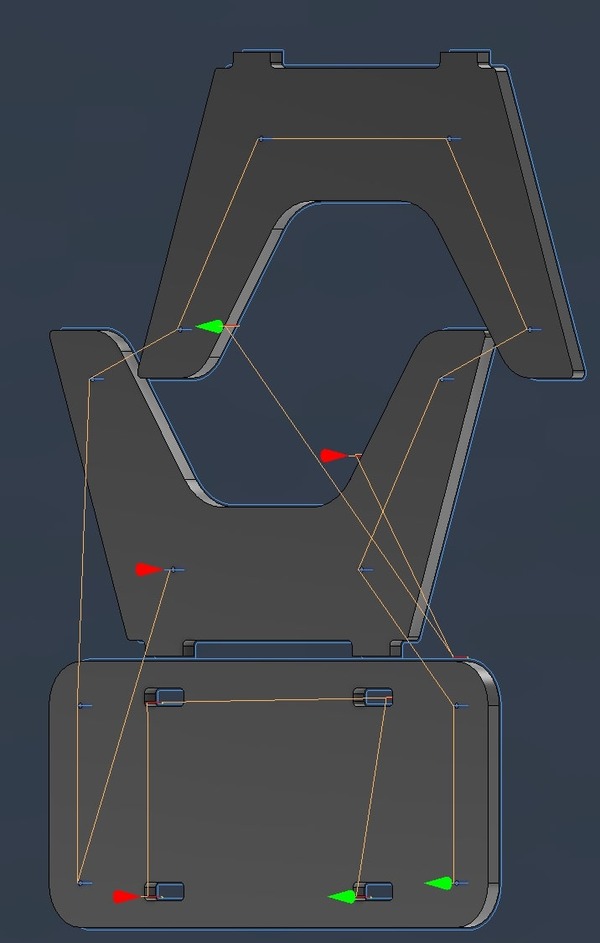
Image f9: Simulation with stock material
Machining and Assembly Process
1. Tool Setup and Zeroing
The CNC process started by installing a 6 mm, 1-flute end mill suitable for cutting wood. I mounted the 18 mm plywood sheet onto the CNC bed, initially using clamps to secure the corners.
Before starting the job, I carefully zeroed the machine:
- X and Y axes: Zeroed by jogging the spindle to the bottom-left corner of the plywood and setting that point as the origin.
- Z axis: Zeroed using the touch-off method on the top surface of the plywood to ensure accurate cutting depth.
Once the setup was confirmed, I loaded the G-code and started the job.
2. Running the Job and Fixturing
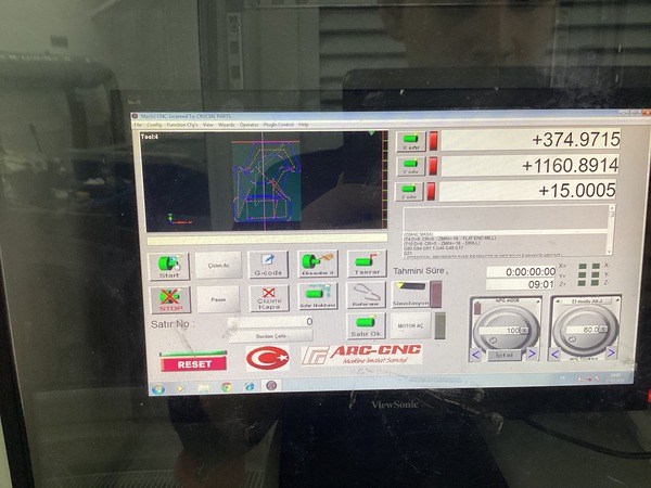
The job was executed using the ARC-CNC controller (Mach3-based). I loaded the G-code exported from Fusion 360 and began with the drilling operation.
To prevent the part from moving during contour cuts, I programmed the machine to pause automatically after drilling. This allowed me to insert screws into the drilled holes, fixing the board firmly onto the sacrificial layer.
After placing the screws, I resumed the job and the machine proceeded with the internal and then external 2D contours.
3. Material and Stock
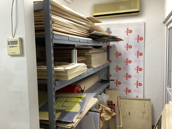
The material used was 18 mm plywood, selected for its durability and suitability for structural assembly. It was sourced from the Fab Lab’s inventory and checked for flatness. The layout was fitted within a 600 mm x 1200 mm sheet.
4. Milling in Progress
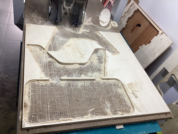
After verifying the setup and simulation, I let the machine complete the operations. Tabs were included in the CAM setup to hold parts in place during machining and were manually removed afterward.
5. Parts Cut
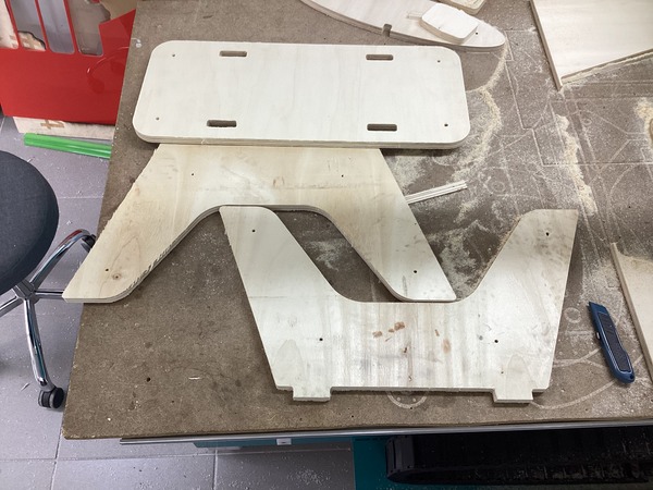
Once the machining was done, I cut the tabs, removed the parts, and sanded the edges. The fit between components was tight and accurate, showing the tolerances were well-tuned for 18 mm plywood.
6. Final Assembly
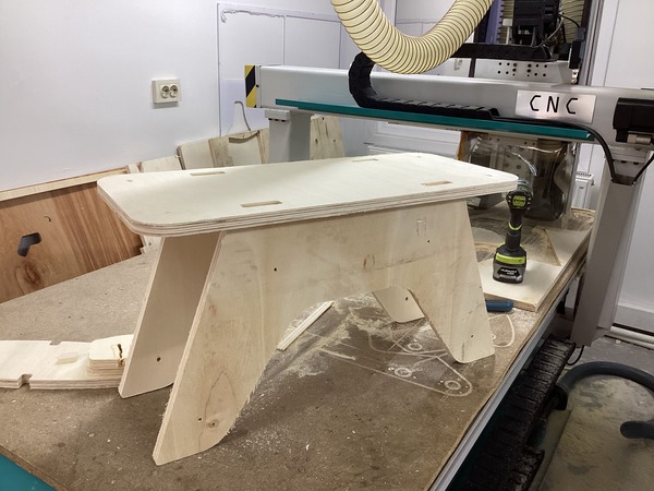
The final structure was assembled using only a press-fit connection. No glue or screws were required. The resulting assembly was stable, strong, and aligned precisely as designed.