Group assignment: demonstrate and compare the toolchains and development workflows for available embedded architectures
1. Raspberry Pi Pico W Overview
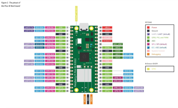
For this week’s assignment, I reviewed the Raspberry Pi Pico, a cost-effective and flexible development board built around the RP2040 microcontroller. This chip includes a dual-core ARM Cortex-M0+ processor capable of running at up to 133 MHz, making it suitable for embedded and real-time applications. It provides 264 KB of SRAM and 2 MB of Flash memory, which support a range of control and processing tasks.
The board includes 26 general-purpose I/O pins, many of which support functions such as I2C, SPI, UART, PWM, and ADC, offering a wide variety of interfacing possibilities for sensors, actuators, and communication devices.
Processor and Performance
- Dual-core ARM Cortex-M0+ processor, up to 133 MHz
- Optimized for low-power, real-time processing
- Includes hardware timers and interrupt capabilities
- Supports deep sleep and dormant modes for power efficiency
Memory
- 264 KB of Static RAM (SRAM)
- 2 MB of onboard QSPI Flash storage
Input/Output Capabilities
- 26 multifunction GPIO pins (22 accessible for general use)
- 8 PWM channels for tasks such as motor or LED control
- 3 analog inputs with 12-bit ADC resolution
- Internal temperature sensor
Communication Interfaces
- I2C, SPI, and UART support for peripheral communication
- Micro-USB port for both power supply and programming
- Programmable using C/C++ or MicroPython
- SWD (Serial Wire Debug) interface available for debugging
Power and Voltage
- Operating voltage range: 1.8V to 5.5V
- Logic level: 3.3V
- Low-power modes suitable for battery-operated systems
Physical Characteristics
- Dimensions: 21 mm x 51 mm
- 40-pin Dual Inline Package (DIP) layout for breadboard compatibility
2. Components
- Arduino Board
- A4988 Stepper Motor Driver
- Stepper Motor
- Potentiometer
- External Power Supply
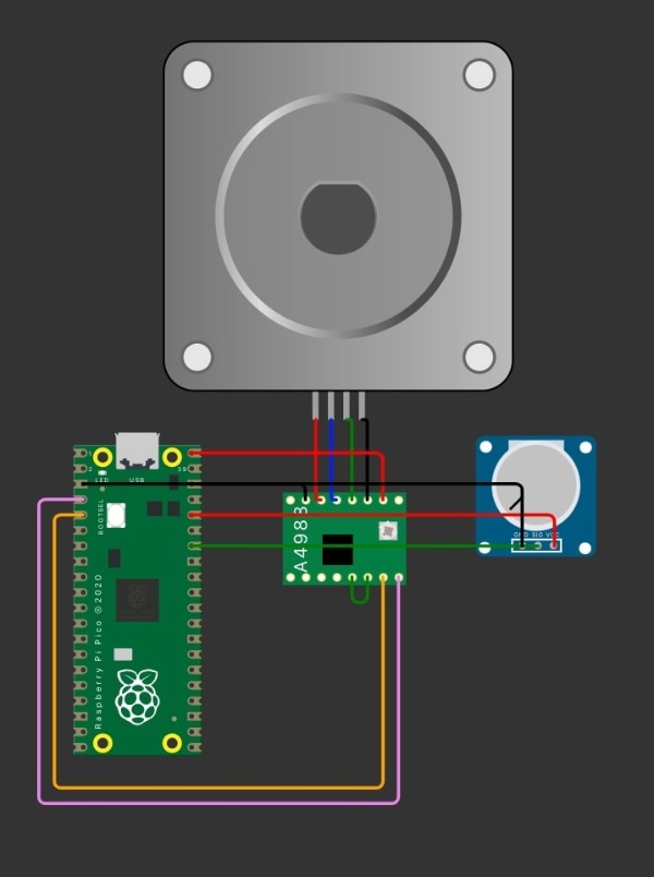
3. Circuit Connections
The stepper motor is connected to the A4988 driver, which is controlled by the Arduino.
STEP(A4988) → Pin 9DIR(A4988) → Pin 8POT(Analog Input) → 28
4. Arduino Code
#define DIR_PIN 2
#define STEP_PIN 3
#define POT_PIN 28

void setup() {
  pinMode(STEP_PIN, OUTPUT);
  pinMode(DIR_PIN, OUTPUT);
  digitalWrite(STEP_PIN, LOW);
}

void loop() {
  int potValue = analogRead(POT_PIN);
  int stepDelay = map(potValue, 0, 1023, 1, 10);


  digitalWrite(DIR_PIN, HIGH);
  for (int i = 0; i < 200; i++) {
    digitalWrite(STEP_PIN, HIGH);
    digitalWrite(STEP_PIN, LOW);
    delay(stepDelay);
  }

  delay(500);


  digitalWrite(DIR_PIN, LOW);
  for (int i = 0; i < 200; i++) {
    digitalWrite(STEP_PIN, HIGH);
    digitalWrite(STEP_PIN, LOW);
    delay(stepDelay);
  }

  delay(1000);
}