Computer-Aided Design Assignment
Introduction
This week we’ve gotten an introduction to computer-aided design—modeling in 2D and 3D, preferably parametrically.
Assignments
Our task for this week is:
- Model (raster, vector, 2D, 3D, render, animate, simulate, …) a possible final project.
- Compress images and videos and post them on our class page.
2D Modeling
Raster:
Notability
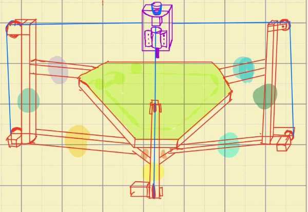
Last week, I created a rough 3D (top-side) sketch of my final project using a raster-based tool on my iPad Air, utilizing the Apple Pencil and the Notability app.
Vector:
Inkscape
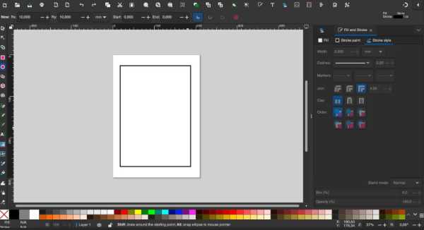
Inkscape is an open-source 2D vector graphics software recommended for our workflow. It offers a non-destructive workflow similar to Fusion 360 making it a great tool for designing laser-cuttable components.
Step 1: Creating a Rectangle
- Select the Rectangle Tool (R).
- Disable fill and apply a 2 px black stroke.
- Open the Path Effects panel.
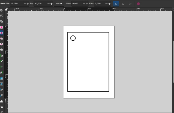
Step 2: Adding a Hole for the Keyring
- Select the Ellipse/Arc Tool.
- Set Rx and Ry to 10 mm for a round hole.
- Position the circle appropriately.
Step 3: Adding Text
- Select the Text Tool (T).
- Choose a font type and size.
- Center the text within the design.
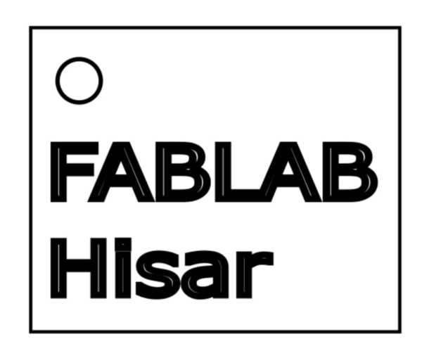
Step 4: Exporting the Design
To ensure compatibility with laser cutters:
- Save the file as an SVG.
- Cutting paths: red (RGB 255,0,0) with a 0.01mm stroke.
- Engraving areas: black (RGB 0,0,0).
3D Modeling
Fusion360
I have been using Fusion 360 for over four years. It is my preferred software due to its integrated design, simulation, and manufacturing capabilities.
I've been using Fusion 360 for over four years, and I will be modeling my final project on this software. I chose it over other CAD programs because of its integrated design, simulation, and manufacturing capabilities, making it an all-in-one solution for product development. One of its biggest advantages is the built-in CAM (Computer-Aided Manufacturing), which eliminates the need for external software and streamlines the transition from design to machining. Its Design History feature allows for parametric modeling with an editable timeline, making design iterations much more efficient. Fusion 360 also utilizes Boundary Representation (BRep) for precise solid modeling, making it ideal for engineering applications. The cloud-based collaboration tools further enhance project management by enabling real-time teamwork and version control, which is crucial for handling complex projects. Beyond its core design capabilities, Fusion 360 offers animation tools for kinematic motion studies, allowing me to visualize assemblies in action. More importantly, its strong simulation features, including stress analysis, modal analysis, and generative design, help optimize parts for real-world applications. The software also supports scripting and automation, making it possible to create generative designs and integrate optimization techniques.
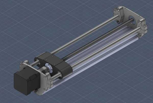
1. Designing the Stepper Motor Mounting Plate
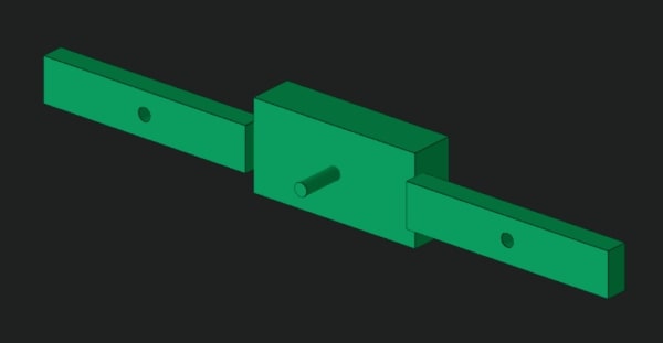
The Stepper Motor Mounting Plate secures the stepper motor and was designed in the main Fusion 360 file.
- Rectangle tool defined the plate's dimensions.
- Circle tools created mounting holes.
- Mirror, Coincident, Midpoint, and Perpendicular constraints ensured symmetry.
- Horizontal/Vertical and Equal constraints maintained alignment.
- Dimension tool set precise hole locations and sizes.
2. Designing and Importing the Nut Housing Block
The Nut Housing Block was designed separately and imported into the main assembly.
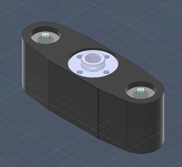
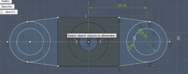
3. Sketching the Nut Housing Block
- Rectangle defined overall dimensions.
- Circle at center for lead screw hole.
- Two Circles for mounting holes.
- Mirror ensured symmetry.
- Coincident aligned features.
- Midpoint placed lead screw hole centrally.
- Perpendicular kept edges aligned.
- Dimension set exact placements and sizes.
4. Extruding the Base and Other Components
The Extrude command converted sketches into 3D solids based on required thickness.
5. Inserting Components from Fusion 360 Library
Except for the stepper motor mounting plate and 8mm guide rods, all other components were inserted from the Fusion 360 library:
- Lead screw
- Bearings
- Linear rail supports
- Fasteners
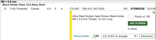
6. Inserting Bolts from McMaster-Carr
7. Component Alignment and Joint Setup
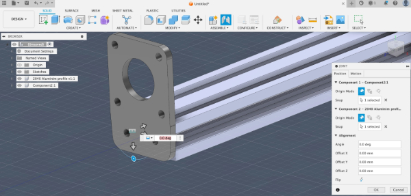
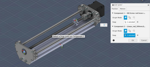
I used motion link to link the cylindirical joint of linear bearings with rotational join of the screw rod.
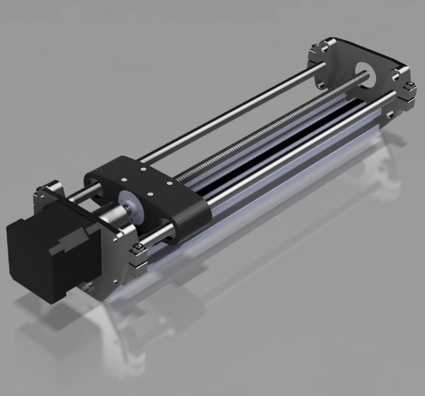
Rendered Image of Final
Onshape
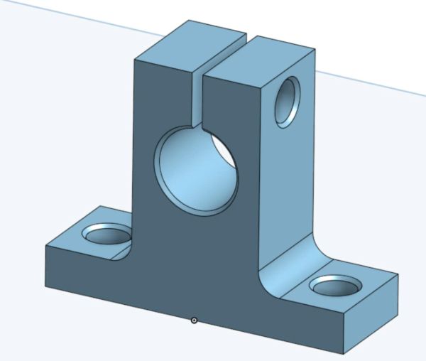
For this project, I will be reverse engineering a shaft holder designed to secure 8mm steel rods. These components are widely used in 3D printers and CNC routers to support linear motion systems.
A similar example can be found in this FabAcademy documentation.
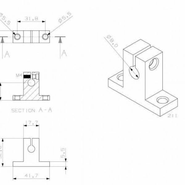
I am going to reverse engineer this shaft holder. It is designed to hold 8mm steel rods.
These pieces are pretty common on 3D printers and CNC routers. For an example, check out this link.
1. Original Part Analysis
The original shaft holder features:
- A central 8mm bore for the rod.
- A clamping mechanism to secure the rod in place.
- Mounting holes for attachment.
- Filleted and chamfered edges for strength and visial purposes
2. CAD Design in Onshape
Step 1: Initial Sketch
- Created the base profile on the front plane.
- Added the 8mm bore and mounting holes.
- Fully constrained the sketch.
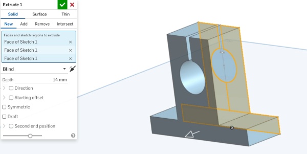
Step 2: Extrusion
- Extruded the base and support section to a depth of 14mm.
- Ensured that the bore hole and split clamp were included.
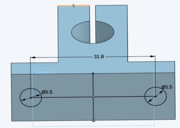
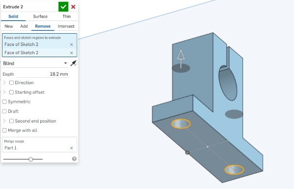
Step 3: Adding Mounting Holes
- Created a new sketch on the top face.
- Added the 5.5mm holes for screws.
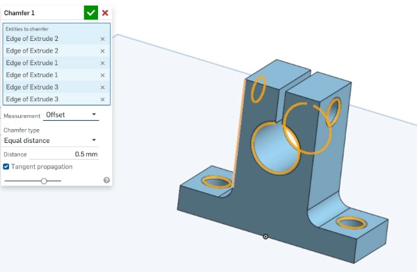
Step 4: Fillets and Chamfers
- Applied a 3mm fillet to the base edges.
- Added a 0.5mm chamfer to the rod bore and mounting holes.
4. Final CAD Model
After completing all operations, I reviewed the final design and made sure all dimensions matched the original part.
OpenSCAD
OpenSCAD is a script-based 3D modeling tool where designs are created using code instead of manual modeling. Unlike traditional CAD software, it focuses on precision and parametric design, making it ideal for iterative improvements and customization. While unusual at first, OpenSCAD offers a surprisingly joyful experience, blending logic and creativity to generate complex models with just a few lines of code.
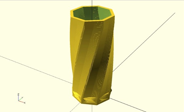
This project is a vase that is generated by extruding a polygonal base, with each layer incrementally rotated and scaled to create a smooth, spiral effect. A hollow inner shell is subtracted to make it functional, and all aspects—height, twist, and thickness—are fully parametric. The result is a customizable, 3D-printable object .)
        // Variables

        vaseRadius = 15;

        vaseWallThickness = 2;

        vaseSides = 8;

        slices =60;

        angleShiftPerSlice = 1;

        radiusIncrease = 10;

        heightPerSlice = 5;

        heightOffset = 0.05;

        sliceIncrease = sin(radiusIncrease) / slices;

        // Vase outer shell

        linear_extrude(height = heightPerSlice, center = false, convexity = 50, twist = 50)

        circle(vaseRadius, $fn=vaseSides);

        // Vase inner shell

        for (a = [1:slices]) {

        translate([0,0,(1*a)])

        rotate([0,0,angleShiftPerSlice*a])

        difference() {

        linear_extrude(height = heightPerSlice + heightOffset, center = true, convexity = 10, twist = 0)

        circle(vaseRadius + (sliceIncrease * a), $fn=vaseSides);

        linear_extrude(height = heightPerSlice + heightOffset + heightOffset, center = true, convexity = 10, twist = 0)

        circle(vaseRadius - vaseWallThickness + (sliceIncrease * a), $fn=vaseSides);

        }

        }
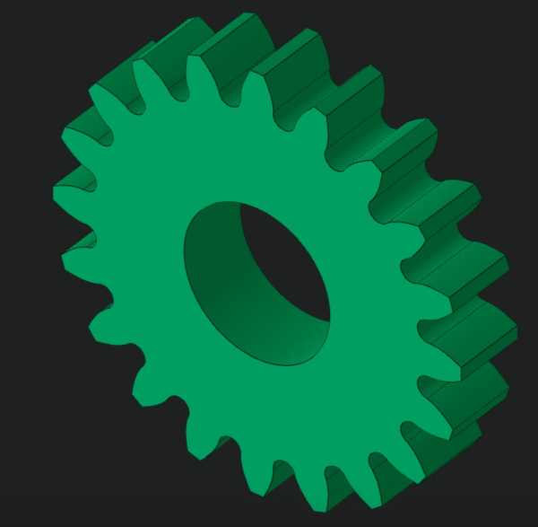
Zoo AI text-to-CAD Generator
Failure (Complex Assembly Failures)
Prompt: "a robotics arm claw"
Success (Single Component with High Detail)
Prompt: "A gear that has 20dp pitch and 28.90mm outer diameter while a hole for a 10mm outer diameter bearing to fit in."
Additional 3D Software
- SolidWorks: Industry-standard, advanced parametric modeling, strong simulation.
- Blender: Free 3D modeling, animation, rendering.