Computer Aided Design
On this week, I worked on Computer-Aided Design (CAD). Since, I hadn't tried any of the tools before, I started experiencing with all of them this week.
2D
Raster
Raster images are images that are made up of dots with unique colors (pixels). To manipulate raster images, there are multiple tools. I used Image Magick. I also used FFmpeg to compress videos.
Image Magick Instructions
To manipulate images, Image Magick is a tool that Fab Academy encourages to use. Among other functions, it involves compressing images and converting different file formats to each other. I used Image Magick to convert a HEIC image into the JPG and compress my image. In this section, I am going to show how to used Image Magick. I benefitted from the Image Magick's website to learn how to download it and from Fab Academy's documentation on some Image Magick commands. First, I used Homebrew to download it by the following command:
brew install imagemagick
Also, Image Magick uses Ghostscript fonts. To download them, I used the following command:
brew install ghostscript
Then, I used the following command to extract the contents of the downloaded package:
tar -xvzf ImageMagick-x86_64-apple-darwin20.1.0.tar.gz
I learned from Fab Academy's documentation that JPG is the compressed version, and PNG is the uncompressed version. To convert PNG to JPG, I used the following command:
convert input.png output.jpg
To compress a JPG file, I used the following command:
convert input.jpg -quality 50% -resize 1000 output.jpg
I also had a HEIC image. To convert it to JPG while reducing the file size and keeping it under 100 kB (use extent=200kb or any other value if you wish so), I used the following command:
magick input.heic -resize 40% -quality 60 -define jpeg:extent=100kb output.jpg
Note: I used ChatGPT-4-o to find the last command. I asked, "How to convert and compress heic to jpg using image magick mac. I want the JPG file to be reduced below 200 KB preferably below 100 kB"
FFmpeg
To compress my videos, I used the FFmpeg tool. First, I downloaded FFmpeg using Homebrew.
brew install ffmpeg
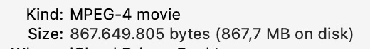
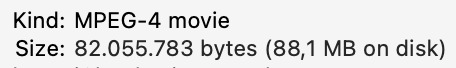
Then, I compressed a sample video, which is approximately 22 minutes long, using the following command. I found this command by asking ChatGPT how to compress videos using FFmpeg.
ffmpeg -i input.mp4 -vcodec libx264 -crf 23 output.mp4
The first image shows the initial size of this video, and the second image shows the final size after compression. It is clear that the size is almost one tenth of the original one.
You could also use the following command to compress it further.
ffmpeg -i input.mp4 -vcodec libx264 -crf 30 -preset slow output.mp4
Also, the following command is used to convert a mov file to an mp4 file while compressing it.
ffmpeg -i input.mov -vcodec libx264 -crf 30 -preset slow -acodec aac -b:a 96k output.mp4
Vector
Vector images consist of lines and shapes. I used Inkscape to design a drawing to be cut from a laser cutter for my final project.
Inkscape
During the learning process, I benefitted from my friend Ismail's Fab Academy page. I also learned about boolean operations (adding or substracting parts of a shape using another image) through a Fab Academy source explaining this. I also benefitted from other sources like a webpage explaining how to draw triangles on Inkscape. I am now going to explain the steps that I went through to make my design:
- Click on the rectangle icon to make one.
- Click on "fill and stroke" and make the rectangle white by clikcing on the white color below.
- Select the rectangle and click on "Stroke paint." Then, select a boarder color. (I used black)
- Click on "Stroke style" and adjust the width of the boarder. (I used 300 px)
- Create a triangle using the "Star/Polygon Tool"
- Adjust corners to 3 and select regular polygon.
- Make an upside down isosceles triangle and allign the corner where the same sides meet with the left down corner of the rectangle.
- Copy the triangle but do not paste it to anywhere.
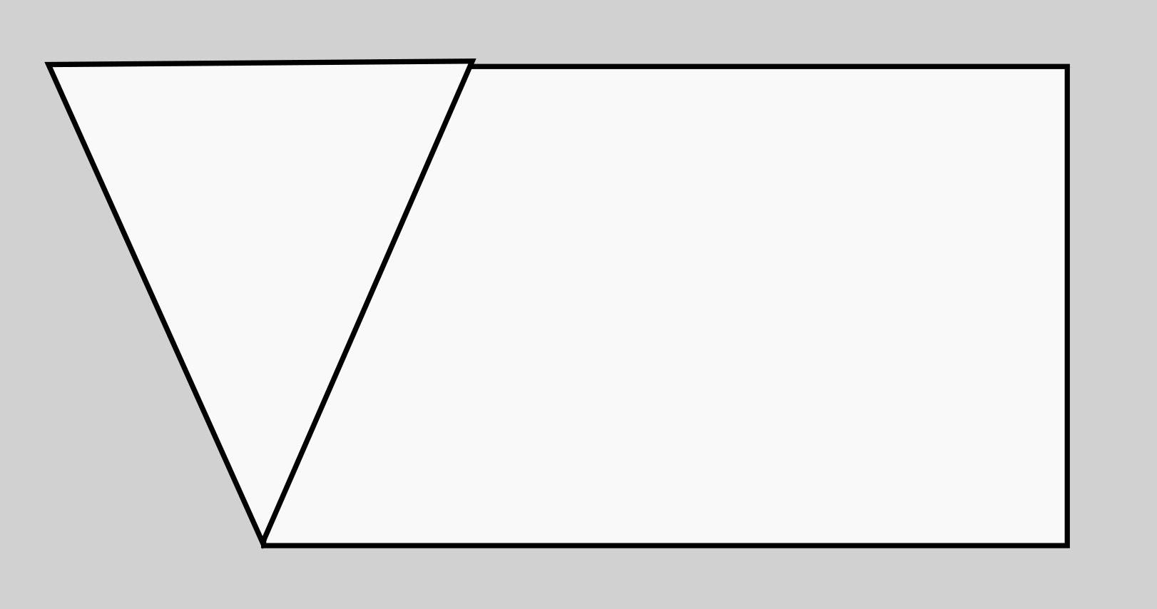
- Select both the triangle and the rectangle.
- Click on "Path" > "Difference" This is called boolean substraction and allows you to substract shapes from other shapes.
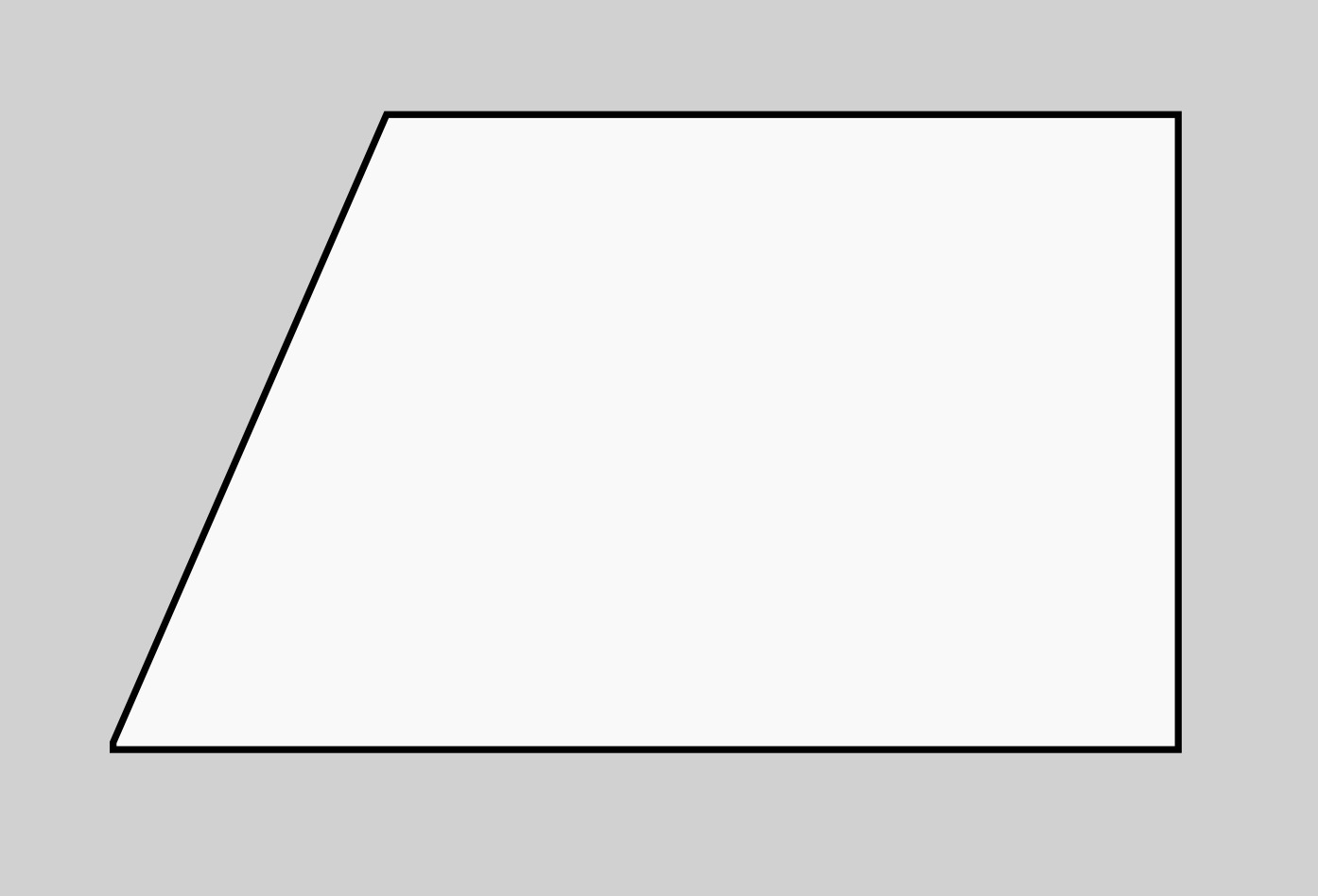
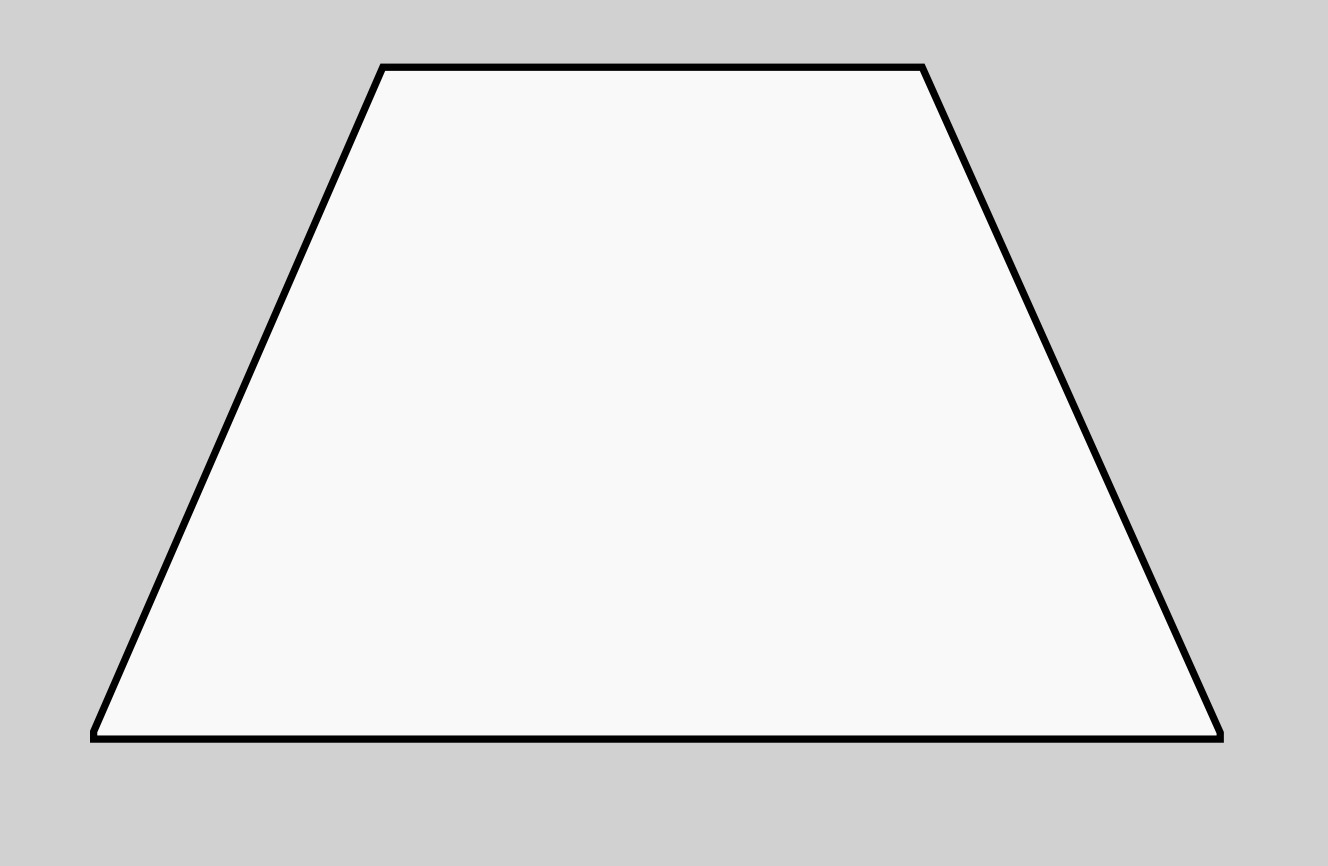
- Apply the same process to make a trapezoid
- Select "Text"
- Adjust the font and other writing settings.
- Write whatever you want (Note: I used 10,000 px and the Arial font)
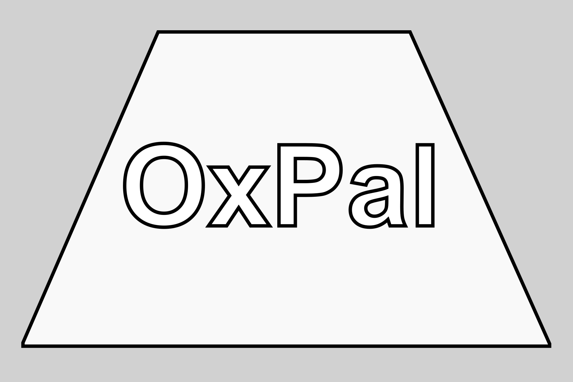
- Save the image as an svg file.
3D
Fusion 360
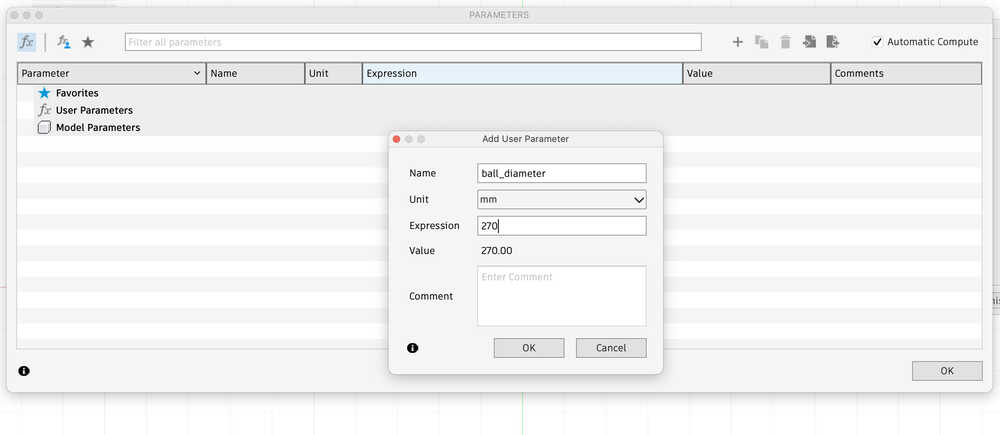
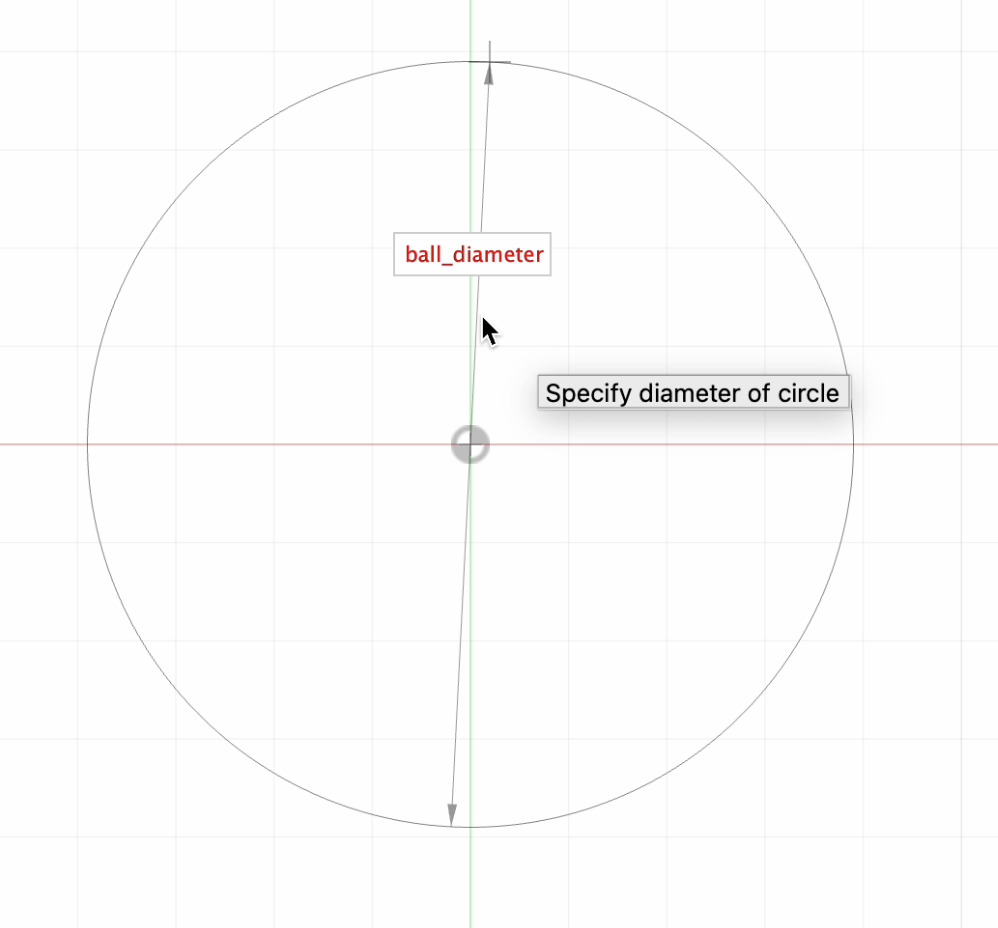
This week, I designed the 3D sketch of my ball-shaped final project parametrically. Since this is my first experience with 3D, I will improve my final project design as Fab Academy continues. I also rendered, animated, and simulated it. In this subpage, I am going to explain my design process.
- First, I defined the diameter of my ball as a parameter with 270 mm. I clicked on Modify > Change Parameters to define each of my parameters.
- Now, I sketched my circle and defined its diameter based on my parameter.
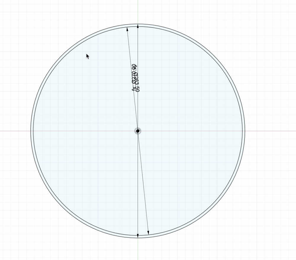
- Then, I defined a new parameter for outer thickness of my ball.
- Next, I sketched another circle and made its diameter, "Ball diameter - Outer Thickness" to arrange the thickness of the ball each time I change its parameter.
- After that, I changed the thickness to 6.5 mm.
- I will add the electronical components of my device from the lower part of my ball. So, in order to remove the lower side of the ball, I defined the length of the hole as a parameter to be 176 mm.
- Then, I drew a line to limit the lower part of the ball to create my hole. I gave the measurement of "length of the whole + 2 * outer thickness of the ball" so that it was based on the outer circle.
- Afterward, I clicked on "Coincident" to allign it with the outer circle.
- To determine the axis of revolution, I drew a vertical line, extending beyond the both circles.
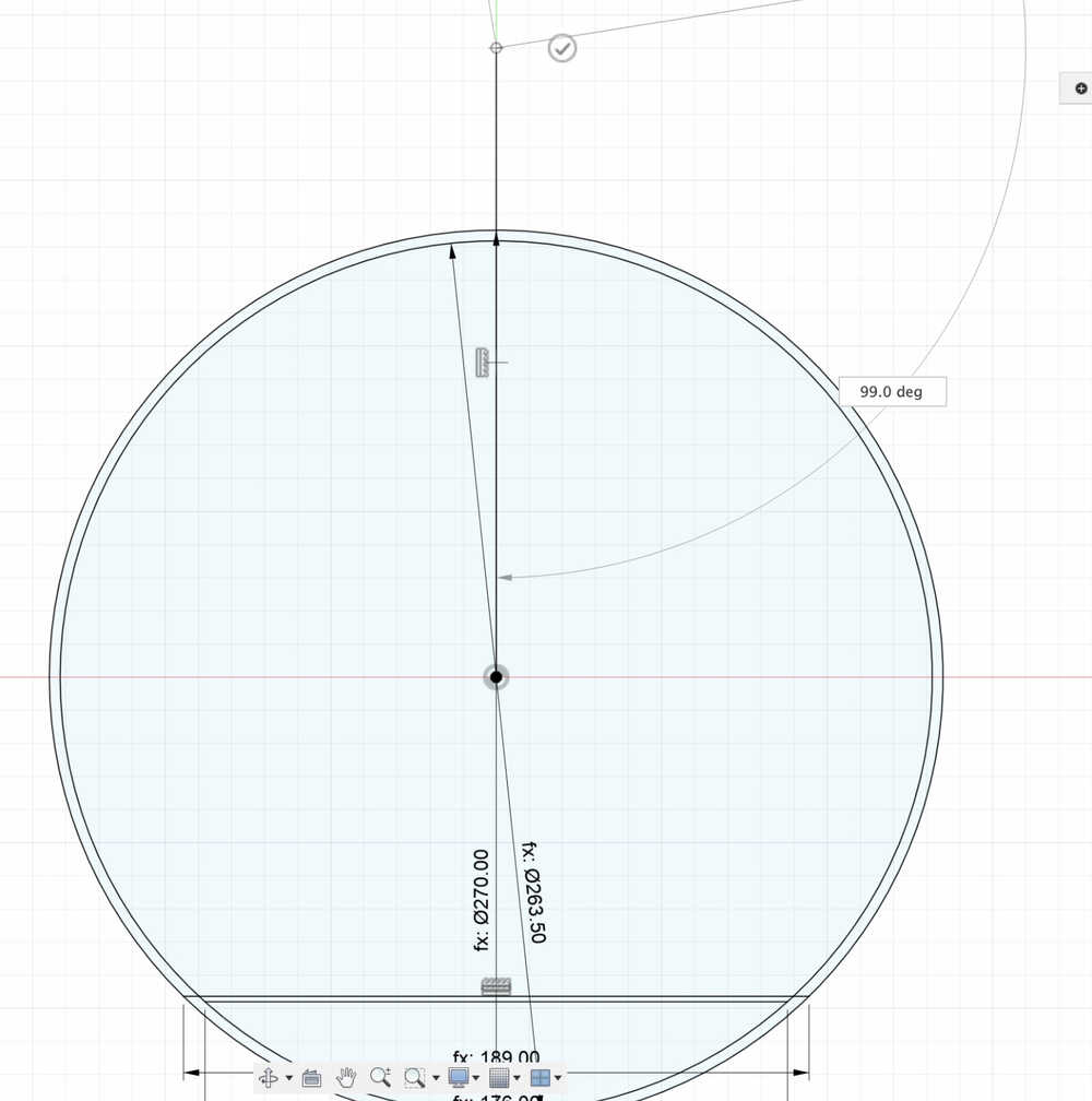
- Using revolve, I turned my sketch into a 3D design.
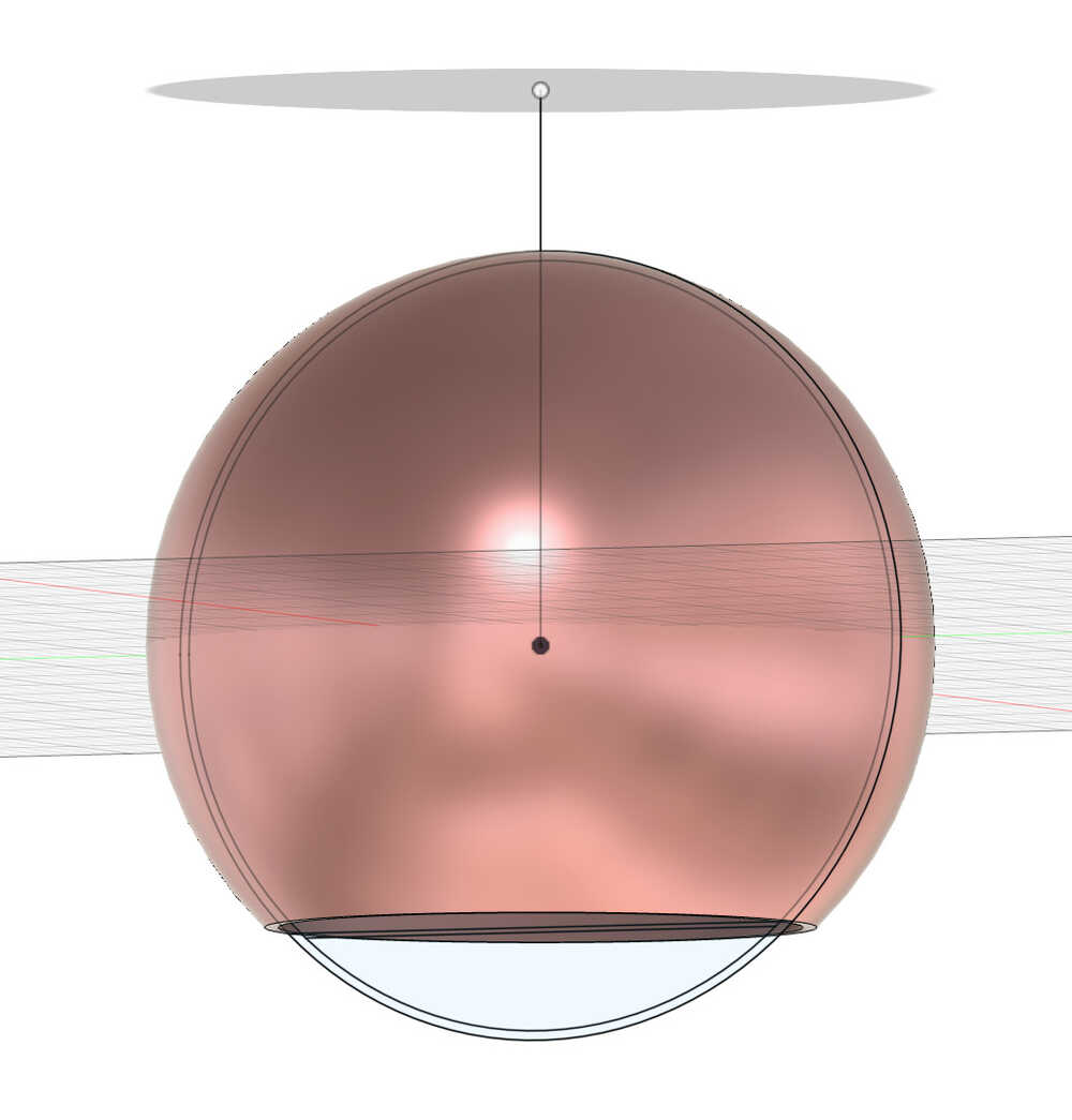
Render
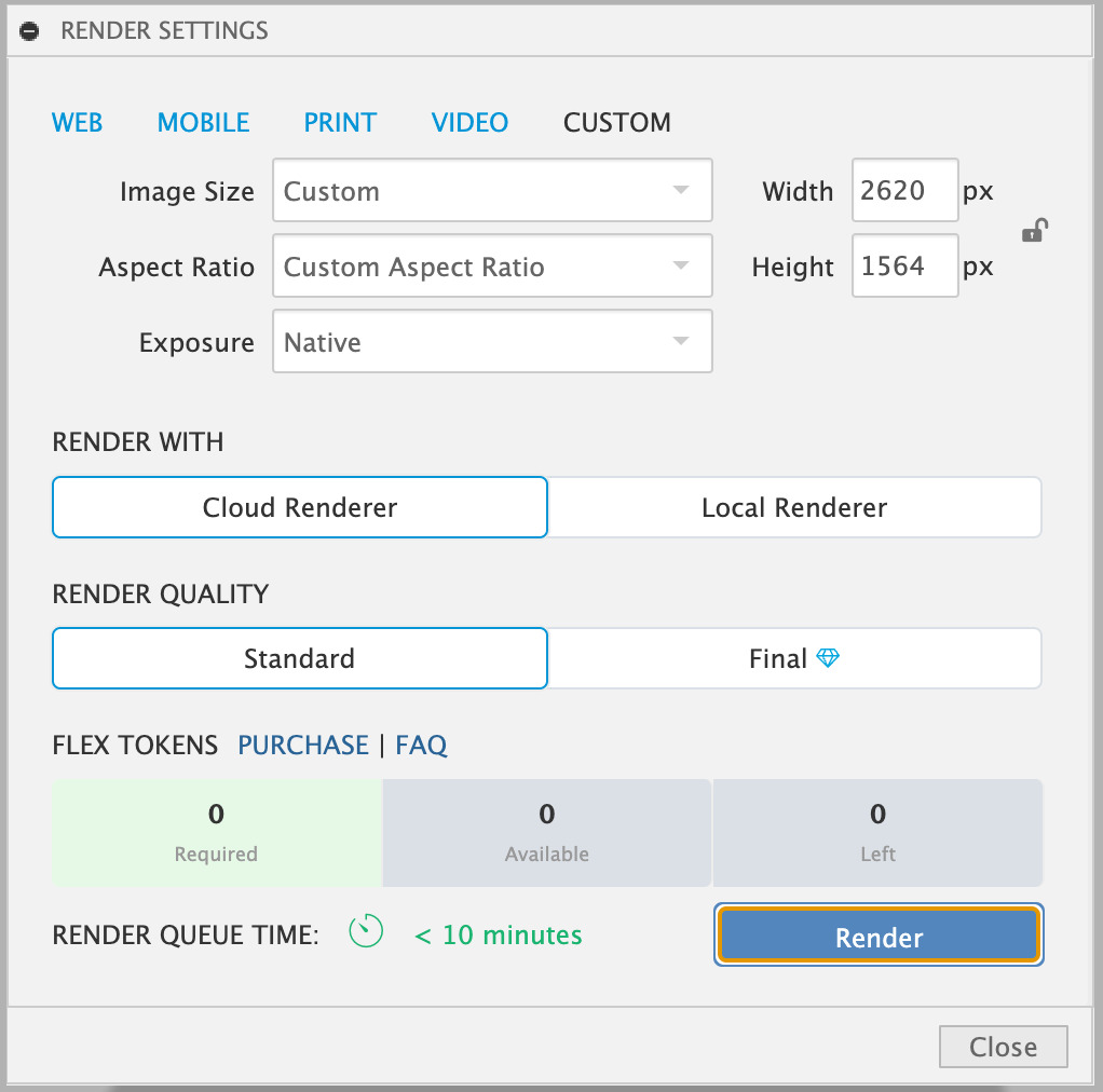
Rendering is creating the final design by adding light and other elements to have a snapshot of the design. First, I adjusted the rendering settings. I chose "Render with Cloud Renderer" and "Standard" as the "Render Quality"
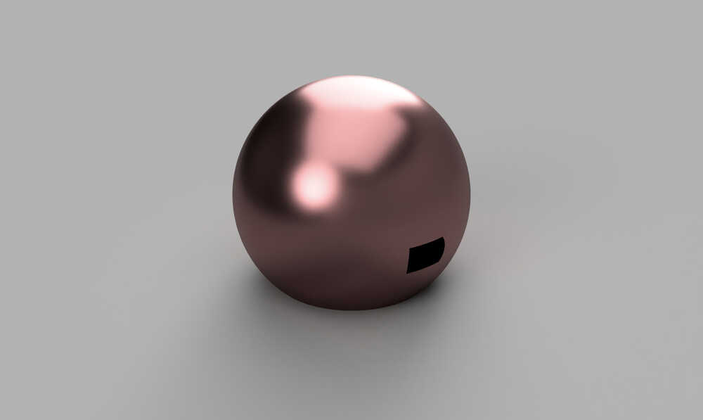
My final Render file is the following.
Animation
I learned how to make an animation in Fusion 360 by wathcing a YouTube video. Then, I selected 5 seconds on the time frame and clicked on "Transform Components" option. Finally, I rotated my OxPal ball. Then, I wanted my ball to move upward while rotating, so I selected another time frame and transformed my ball upward. Finally, to change the duration of my animation (to make it rotate and move simultaneously), I right clicked on the animation frame and clicked on "Duration." Afterward, I clicked on "Publish" to convert it into an mp4 file.
Conclusions
This week, I learned how to compress images and videos, 2D and 3D design, and rendering and animating my design.
You can access my 3D design through these zip files:
(Note: Before exporting these files, I made some furhter additions to my final project, so they also appear when opening these files)

STEP File
3mf File
f3d File
Inkscape svg File