Week 10: Output Devices
Group Assignment
Click to access the group assignmentMy Board
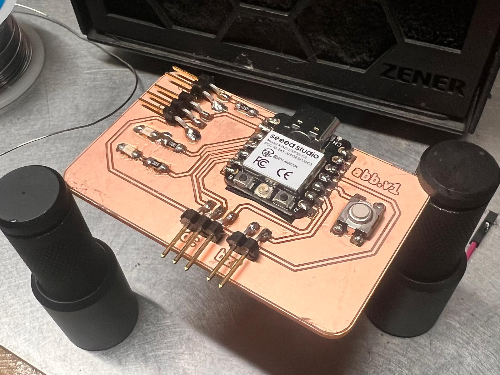
I used my custom ESP32-C3 board from Week 8.
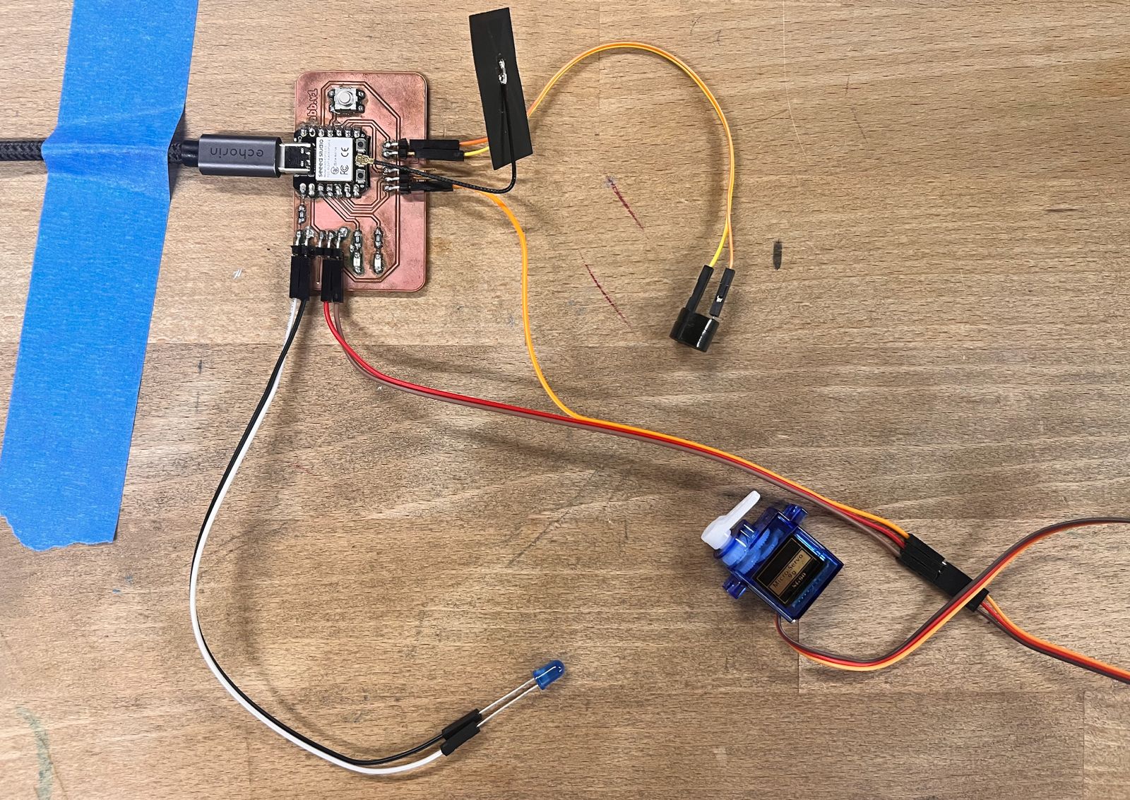
Wiring
This project uses three output devices. Here's how each is connected:
LED Wiring
- Long leg (anode) to GPIO 2 (D0) through a 330Ω resistor
- Short leg (cathode) to GND
Buzzer Wiring
- + pin to GPIO 9 (D9)
- – pin to GND
Servo Wiring
- Red wire (VCC) to 3.3V from ESP32-C3
- Brown/black wire (GND) to GND
- Orange/yellow wire (signal) to GPIO 6 (D6)
Even though the SG90 servo is meant for 5V, it worked for light testing at 3.3V.
Shared Ground
All components share the same ground with the microcontroller to ensure proper signal reference.
Wiring Diagram

Finished Setup In Real Life
Programming Process
- Board: XIAO_ESP32C3 selected in Arduino IDE
- Used
ESP32Servolibrary for servo control - Pin mapping:
- Servo: GPIO 6
- LED: GPIO 2
- Buzzer: GPIO 9
- To upload, I manually entered boot mode:
- Hold BOOT, tap RESET, release RESET, then upload
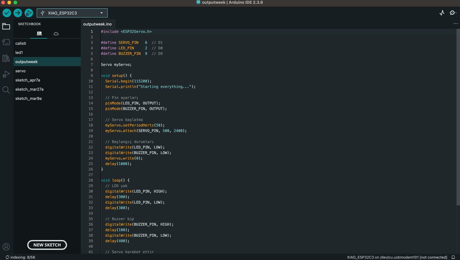
Source Code
#include <ESP32Servo.h>

#define SERVO_PIN   6  // GPIO 6
#define LED_PIN     2  // GPIO 2
#define BUZZER_PIN  9  // GPIO 9

Servo myServo;

void setup() {
  Serial.begin(115200);
  Serial.println("Starting...");

  pinMode(LED_PIN, OUTPUT);
  pinMode(BUZZER_PIN, OUTPUT);

  myServo.setPeriodHertz(50);
  myServo.attach(SERVO_PIN, 500, 2400);
  myServo.write(0);
  delay(1000);
}

void loop() {
  digitalWrite(LED_PIN, HIGH);
  delay(300);
  digitalWrite(LED_PIN, LOW);
  delay(300);

  digitalWrite(BUZZER_PIN, HIGH);
  delay(100);
  digitalWrite(BUZZER_PIN, LOW);
  delay(400);

  for (int angle = 0; angle <= 180; angle += 30) {
    myServo.write(angle);
    delay(300);
  }

  for (int angle = 180; angle >= 0; angle -= 30) {
    myServo.write(angle);
    delay(300);
  }
}
Problems & Solutions
- Servo didn't move → Changed pin to GPIO 6
- Upload error → Solved using BOOT + RESET method
Video of the Working Setup
What I Learned
- How PWM works and how ESP32Servo library generates it
- That servos can function on 3.3V in light-load scenarios
- That not all GPIO pins on ESP32-C3 support PWM
- Importance of shared GND between all components
Hero Shot