
Fab Academy
What I Knew Beforehand
Input Devices — Reading a Pushbutton on the PitchLight PCB
Group assignment
Probe an input device's analog levels and digital signals. Document your work on the group work page and reflect on your individual page what you learned.
Individual assignment
Measure something: add a sensor to a microcontroller board you have designed and read it.
Before this week I understood that input devices are the sensors that allow a microcontroller to perceive the physical world — buttons, switches, potentiometers, distance sensors. What I had not done was wire one to a board I had designed myself and read it programmatically.
My board from Week 6 — the Pitch timer PCB — already had a pushbutton footprint connected to pin D10 of the XIAO RP2040. This week I used that existing hardware to complete the individual assignment: add a sensor to a board I designed and read it.
This assignment used the PCB I had already milled in Week 8, reading the state of the pushbutton on pin D10 of the XIAO RP2040. The exercise was technically straightforward but it clarified something conceptually important: an input device is what gives an embedded system the capacity to respond rather than just execute. Without inputs, a device runs a fixed sequence regardless of the world around it. For my final project, the primary input is the Nextion touch display, which sends UART commands to the XIAO rather than a simple digital signal. The pushbutton exercise provided the baseline understanding of digital state, pull-up logic, debounce that made the UART command parsing in Week 10 much more intuitive.
Group assignment I worked with my colleague Jhasmin Ayala
Check this link
The Input Device — Pushbutton on Pin D10
A pushbutton (tactile switch) is a momentary digital input: it has two states — open (no connection, reads HIGH when using internal pull-up) and closed (connects the pin to GND, reads LOW). It is the simplest possible digital input device and a fundamental building block in embedded systems.
During week 6, I designed a board with a pushbutton wired between pin D10 of the XIAO RP2040 and GND. The pin is configured as INPUT and uses the microcontroller's internal pull-up resistor, so:
| Button state | Pin D10 reads | Serial output |
|---|---|---|
| Not pressed (open circuit) | HIGH (1) | Pushbutton Closed |
| Pressed (connected to GND) | LOW (0) | Pushbutton Open |
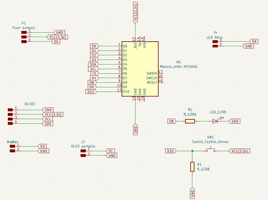
The Pitch timer PCB (milled in Week 8 on the Makera Carvera). The pushbutton is located at the D10 footprint. When pressed, it connects pin D10 to GND; when released, the internal pull-up holds D0 HIGH. All other components — the XIAO RP2040, display connector J6, LED strip connector J4, buzzer connector J5, and screw terminals J1–J3 — are also visible.
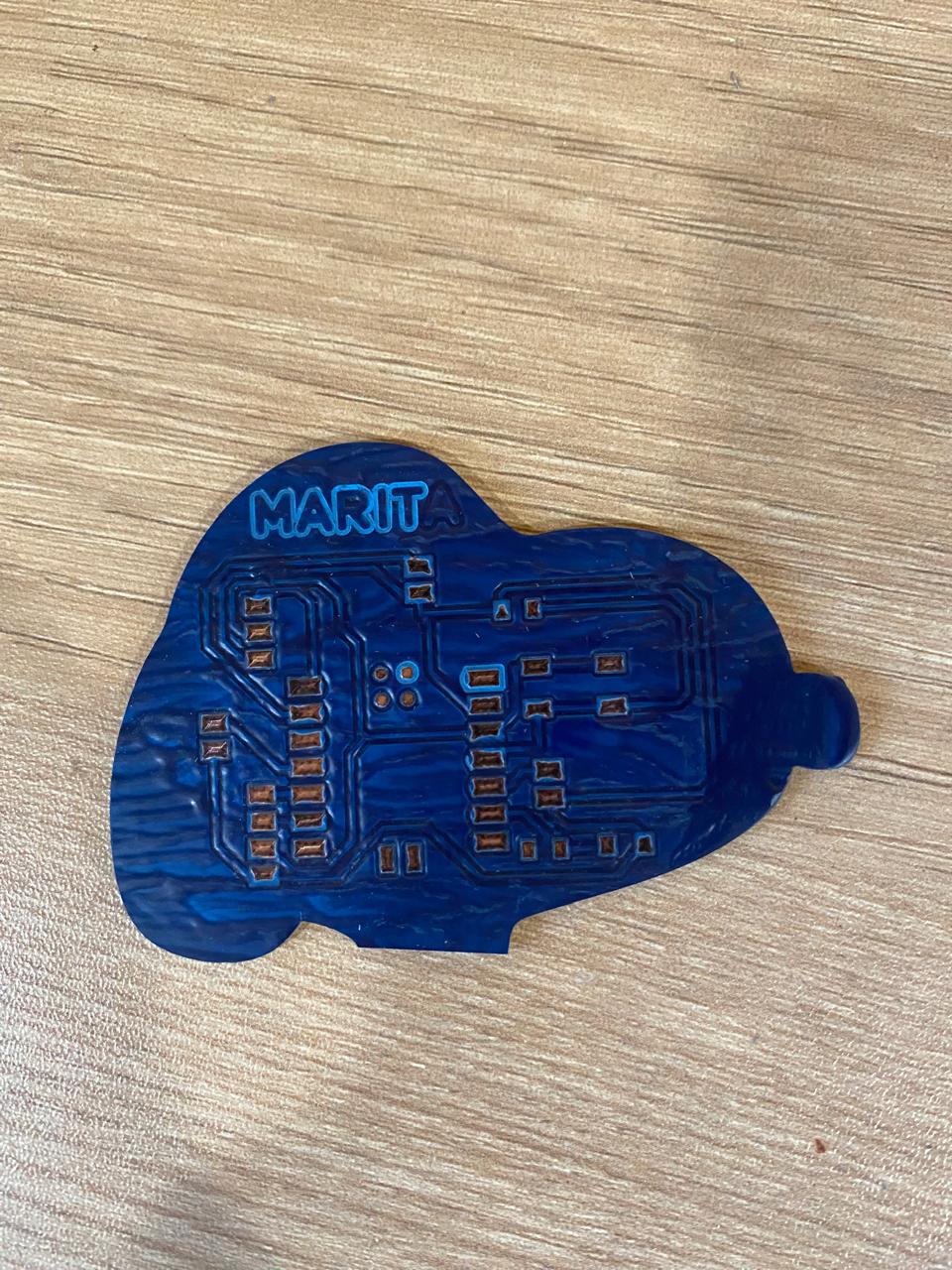
The Pitch timer PCB (milled in Week 8 on the Makera Carvera). The pushbutton is located at the D10 footprint. When pressed, it connects pin D10 to GND; when released, the internal pull-up holds D0 HIGH. All other components — the XIAO RP2040, display connector J6, LED strip connector J4, buzzer connector J5, and screw terminals J1–J3 — are also visible.
Code — Reading the Pushbutton
The firmware reads the pushbutton state every loop iteration using digitalRead() and reports the result over the Serial port at 9600 baud. The logic is inverted relative to the raw pin value because of the pull-up configuration: HIGH means open, LOW means closed.
// Week 9 — Input Devices
// Board: PitchLight PCB (Week 8) — XIAO RP2040
// Input: Pushbutton on pin D10 (wired to GND; internal pull-up active)
// Output: Serial monitor — reports button state at 9600 baud
#define pushbutton D10
bool status;
void setup() {
Serial.begin(9600);
pinMode(pushbutton, INPUT); // internal pull-up keeps D10 HIGH when open
}
void loop() {
status = digitalRead(pushbutton);
if (status) {
Serial.write("Pushbutton Open\n"); >// HIGH → not pressed
}
else {
Serial.write("Pushbutton Closed\n"); // LOW → pressed (D10 pulled to GND)
}
delay(200); // debounce delay — avoids flooding the serial port
}
Result — Serial Monitor Output
With the firmware uploaded via the Arduino IDE and the Serial Monitor open at 9600 baud, the board correctly reports the pushbutton state in real time:
Pushbutton Open
Pushbutton Open
Pushbutton Open
Pushbutton Closed
Pushbutton Closed
Pushbutton Closed
Pushbutton Open
Pushbutton Open
Pushbutton Open
Pushbutton Open
Pushbutton Closed
Pushbutton Closed
Pushbutton Closed
Pushbutton Open
Pushbutton Open
Reflections
This week confirmed something I had understood conceptually but not yet experienced in practice: the difference between an input and an output is more than a wiring direction. An input device gives a system the ability to respond — to change its behavior based on something happening in the physical world. Without inputs, a device can only execute a fixed sequence. With even the simplest input — a pushbutton — it becomes interactive.
Using my own milled PCB for this test also reinforced the value of designing hardware with flexibility in mind. The pushbutton footprint on D10 was placed during the Week 8 design phase without knowing exactly how it would be used. Having it available this week meant I could complete the input assignment on a board I had designed and built myself — which is exactly what the Fab Academy program asks for.
Licensed under CC BY-NC-SA 4.0 — © Marita Chang