In entrepreneurship workshops and pitch competitions, managing presentation time is a constant challenge. Judges and facilitators typically rely on manual stopwatches or phone timers, which require someone's dedicated attention and still fail to communicate urgency to the presenter in a natural, intuitive way. The presenter either doesn't know how much time they have left, or finds out too late.
The result is pitches that run over, judges who lose focus, and presenters who leave without understanding how time affected their performance.
The Solution
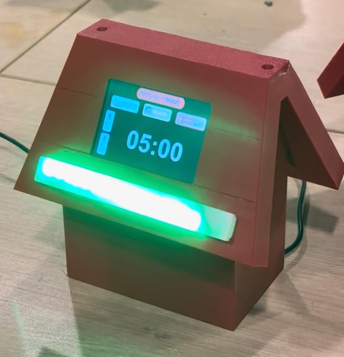
Pitch timer is an interactive timer designed specifically for entrepreneurship workshops. It gives the presenter a clear, continuous visual signal of remaining time through a color-changing LED strip, an HMI touch display showing the countdown in real time, and an auditory alert when time expires — all in a compact, self-contained device that sits on a table or podium without requiring any manual intervention from a facilitator.
The enclosure is designed as a miniature red house — a reference to the iconic doghouse from the Snoopy comic strip, which is my favorite character. The form makes the device immediately recognizable and friendly on a workshop table, rather than intimidating or technical-looking.
System Overview
Pitch timer integrates three hardware subsystems controlled by a single microcontroller:
Subsystem
Component
Function
Display
Nextion NX4832T035_011 — 3.5" HMI touchscreen
Shows the countdown (MM:SS); touch buttons for START, PAUSE, RESET and preset selection (3, 4, or 5 minutes)
LED indicator
WS2812B NeoPixel strip — 16 LEDs
Color changes in real time: Green → Yellow → Red as time decreases
Audio alert
Passive buzzer
5-second tone at 2 kHz when countdown reaches zero
Microcontroller
Seeed XIAO RP2040
Coordinates all subsystems via a non-blocking millis() state machine; communicates with Nextion via UART at 9600 baud
PCB
Custom board — milled at ESAN Fab Lab on Makera Carvera
Connects the XIAO RP2040 to all connectors (LED strip J4, buzzer J5, display J6, three 5V screw terminals J1–J3)
Enclosure
3D-printed PLA — Snoopy house design, 3 printed parts
Houses all electronics; LED diffuser in laser-cut transparent acrylic; roof holds the display at a user-facing angle
Hardware
The complete component list and unit costs are documented in the Bill of Materials on the Week 18 page:
Custom PCB (FR4 copper-clad, milled on Makera Carvera)
3× 2-pin screw terminals for 5V power input
3D-printed PLA+ enclosure (House + roof)
Laser-cut transparent acrylic LED diffuser
M3 screws and standoffs for assembly
PCB
The PCB was redesigned in KiCad and milled at the ESAN Fab Lab during Week 8. The board connects the XIAO RP2040 to four external connectors — the LED strip (J4, D0), the buzzer (J5, D1), the Nextion display (J6, UART TX/RX), and three 5V power screw terminals (J1, J2, J3). All traces are on the front copper layer; the board was milled on the Makera Carvera using a 1/64" isolation bit and a 1/32" outline bit via the Mods CAM workflow.
The firmware runs on the XIAO RP2040 using the Arduino IDE. It implements a non-blocking state machine with states driven by millis(). The display is updated every second via UART; the LED color is recalculated at each tick based on remaining time relative to the selected preset; the buzzer fires a 2 kHz tone for 5 seconds when the countdown reaches zero.
The Nextion display sends text commands over UART (START, PAUSE, RESET, PRESET:3/4/5) which the firmware parses in a character-by-character ring buffer. The complete code and Nextion .tft file were tested and documented in Week 10:
The enclosure was designed in Fusion 360 as a miniature house inspired by Snoopy's iconic red doghouse. The design is organized into three printed parts (House, roof) plus a laser-cut transparent acrylic diffuser for the LED strip. The file is named Snoopy v20 in the Fusion 360 browser, reflecting the number of design iterations required to get all fits and clearances right.
Part 1 — CASA (Base Body)
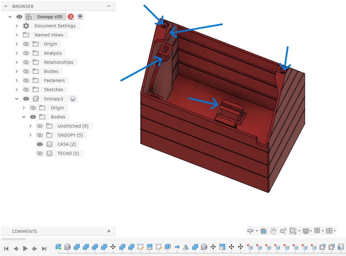
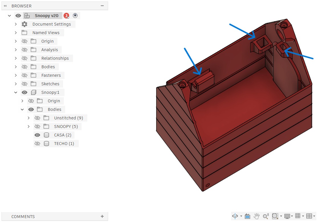
The CASA is the main enclosure body. It houses the PCB, the buzzer, the wiring for all connectors, and the LED strip channel. Key design features:
Top opening for inserting the passive buzzer
Bottom bracket — a recessed holder that secures the PCB inside the enclosure without screws
Two top holes for M3 screws to join the roof to the CASA
Cable routing channels — internal guides that keep wiring organized between the PCB and the display/LED connectors
CASA — front-interior view. Blue arrows indicate: the buzzer insertion opening (top), the PCB bracket (bottom-center), the M3 screw holes (top corners), and the cable routing guides (side walls).
CASA — rear-interior view. Blue arrows highlight the display cable entry point (right side), the connector clearance channel (left), and the PCB bracket recess (bottom). The stepped exterior walls replicate the siding texture of Snoopy's house.
Part 2 — Roof
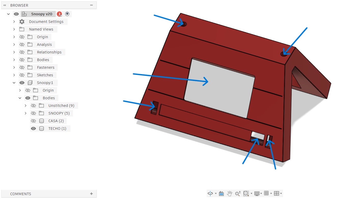
The roof holds the Nextion HMI display at an angled position facing the audience and clips onto the CASA body. Key design features:
Display window — a rectangular cutout sized exactly for the Nextion NX4832T035 (80.5 × 57.5 mm visible area)
Two M3 screw holes (top corners) that align with the CASA body holes for secure roof–base attachment
USB-C port access — a slot at the bottom-right allows the XIAO RP2040's USB-C connector to be reached for programming without disassembly
Power connector slot — a second bottom cutout for the external 5V power cable
TECHO — exterior view. Blue arrows indicate: the two M3 screw holes (top corners), the Nextion display window (center), the USB-C access slot (bottom-left), and the power cable slot (bottom-right).
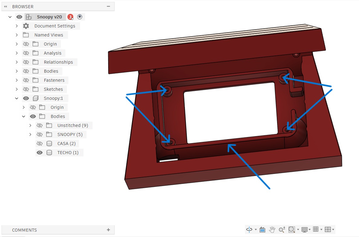
TECHO — interior view showing the display mounting frame. Blue arrows indicate the four M3 screw bosses at the corners of the display opening. The Nextion display PCB sits in this frame and is secured with four M3 screws.
Part 3 — DIFUSOR LED (LED Diffuser Channel)
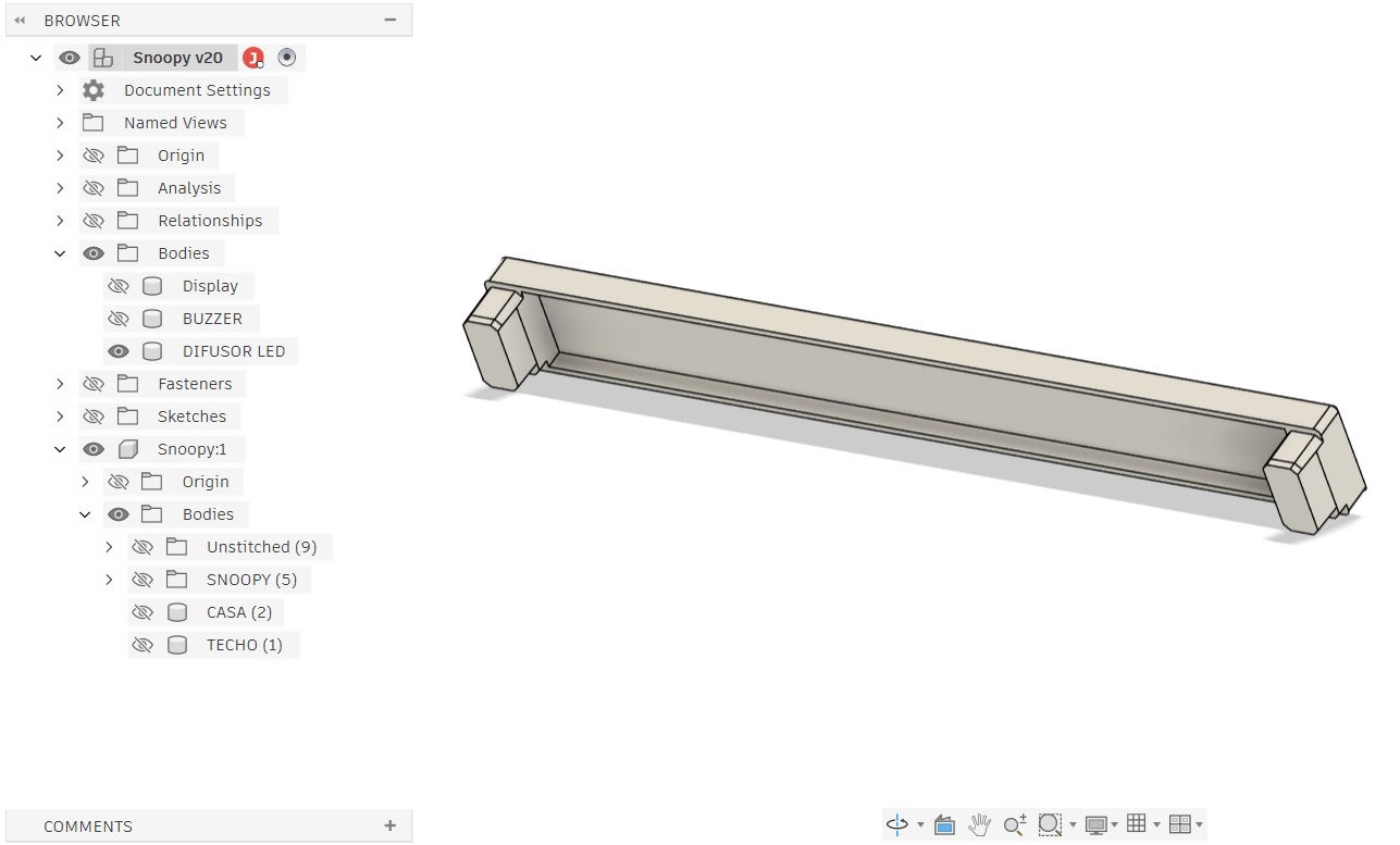
The DIFUSOR LED is a long, U-shaped channel that sits along the front base of the CASA enclosure and holds the WS2812B LED strip. It is designed in transparent or translucent PLA (or laser-cut transparent acrylic) to diffuse the LED light evenly across the full width of the device, preventing hot spots and creating a smooth color gradient effect visible to the audience.
Channel width and depth dimensioned to fit the WS2812B strip (10 mm wide) with a snap-fit retainer
Mounting tabs at both ends that slot into the CASA body
Cable exit at one end for the data and power wires to the PCB
DIFUSOR LED — the LED strip diffuser channel, shown isolated in Fusion 360 (DIFUSOR LED body visible; Display and BUZZER hidden). The U-shaped profile holds the WS2812B strip; mounting tabs at each end lock into the CASA body. Material: transparent or translucent PLA, or laser-cut transparent acrylic for maximum light diffusion.
System Integration
During Week 16, the enclosure was modified to ensure all components fit correctly and can be assembled in the right order. Clearances were adjusted for the PCB bracket, connector positions were aligned with the slots in the CASA walls, and the display mount geometry was refined to eliminate play. The complete integration process is documented on the Week 16 page:
System integration and enclosure modifications (Week 16)
Week-16
Reflections
pitch timer started as a sketch on paper in Week 1 — a vague idea about a timer that changes color. By the time it reached its current form, it had passed through KiCad schematic design, PCB milling on the Carvera, Nextion Editor UI design, Arduino firmware, and twenty iterations of a Fusion 360 enclosure. Each week of Fab Academy contributed a layer — not as a collection of disconnected skills, but as a progressive deepening of the same project.
The most important design insight came late: the LED strip is not just a timer indicator. It is the primary communication channel between the device and the presenter. Everything else — the display, the buzzer, the touch buttons — is secondary. A presenter in the middle of a pitch does not look at the display. They see the color of the light in their peripheral vision. That realization reshaped the color thresholds and the physical placement of the diffuser.
Building this device from raw materials — from a blank PCB substrate to a running embedded system inside a 3D-printed enclosure — has changed how I think about what is possible in a Fab Lab. The barrier between an idea and a physical, functional product is much lower than I understood before this program. That is the lesson I will carry into my work at Innova ESAN.
Developing my project through Fab Academy has been a challenge, but also a powerful motivation to keep learning and keep creating. Technology is getting closer and closer to people — and making incredible things is truly possible. I hope to continue exploring this wonderful world that the program has opened up for me, and I hope to keep inspiring my students and entrepreneurs to dare to experiment, to unleash their creativity, and to innovate continuously. As I always say: being in the Fab Lab is as much fun as being in Disneyland!