
Fab Academy
Electronics Production — Milling and Assembling the pitch timer PCB
- June, 2026
Group assignment
Measure the power consumption of an output device.Individual assignment
Add an output device to a microcontroller board you've designed, and program it to do something.
What I knew beforehand
Before this week I had no experience milling PCBs or producing a physical circuit board from scratch. My background is in economics and entrepreneurship — the closest analogy I had for this process was managing a production workflow: a sequence of steps where each one has a precise specification, and an error at any stage propagates into every stage that follows.
What I did bring from previous weeks was the schematic and PCB layout I had designed in KiCad for my final project, pitch timer. This week was the moment to take those files off the screen and turn them into copper and FR4. The individual assignment asked me to add an output device to a board I had already designed and program it to do something — which for pitch timer meant connecting and programming all three output devices together: the Nextion HMI display, the WS2812B LED strip, and the passive buzzer.
This week's documentation covers a critical milestone: taking the PCB I designed in Week 6 off the screen and milling it in copper on the Makera Carvera. The workflow — KiCad → Gerber → Gerber2PNG → Mods → Carvera Controller — was new to me in every step. What made it significant was that this was not a practice board; it was the actual PCB for my final project, and by the end of the week it was milled, soldered, and running firmware that coordinated the Nextion display, the LED strip, and the buzzer simultaneously. The process also gave me a concrete appreciation of something abstract: that in hardware, iteration is expensive in a way that software iteration is not. A bad trace on a milled board means starting the milling process over.
Group assignment
I worked with my colleague Jhasmin Ayala
Check this link Individual Assignment — The Pitch timer PCBI modified the PCB I originally designed in Week 6 to use it in my final project. The updated board is designed to connect:
- (01) WS2812B RGB LED strip
- (01) Passive buzzer
- (01) Nextion NX4832T035_011 HMI display
- Three 2-pin screw terminals for 5V external power input
The result is shown in the schematic and PCB layout below:
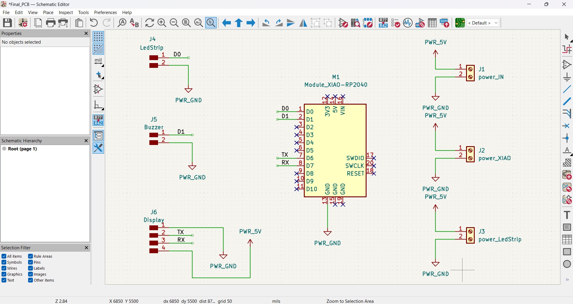
KiCad Schematic Editor — Final_PCB schematic. The XIAO RP2040 module (M1) is connected to the LED strip (J4, D0), buzzer (J5, D1), Nextion display (J6, TX/RX), and three 5V power screw terminals (J1, J2, J3).
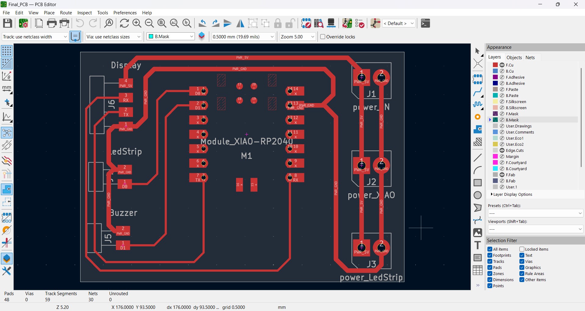
KiCad PCB Editor — completed PCB layout with all traces routed on the F.Cu layer. Board dimensions: 57 × 40.51 mm. 59 track segments. 0 unrouted.
The Machine: Makera Carvera
At the ESAN Fab Lab we have the Makera Carvera — a smart desktop CNC router designed for milling, drilling, engraving and turning diverse materials from home or the workshop. It stands out for automating complex manual processes such as bit changes and leveling.
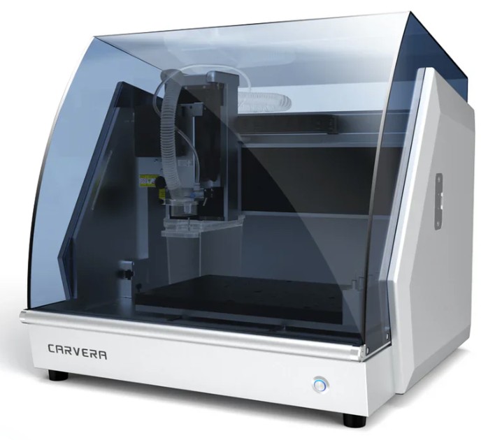
The Makera Carvera desktop CNC router — enclosed aluminum-and-steel frame, transparent hood for visual monitoring during operation.
Key technical specifications:
Specification Value Work area (X × Y × Z) 360 × 240 × 140 mm Spindle 200 W motor, up to 13,000 RPM Automatic Tool Change (ATC) Multiple bits, automatic change in <10 seconds, no manual intervention Auto-leveling probe Integrated — adjusts height to the millimeter to avoid machining errors on uneven surfaces Movement precision 0.01 mm Axes 3-axis; compatible with optional 4th rotary axis module Laser module (optional) 10 W — engraving and light cutting of soft materials Compatible materials Wood, acrylic, PVC, aluminum, brass, carbon fiber, resins, PCB (FR4) Dimensions / Weight 580 × 520 × 540 mm / ~42–50 kg Connectivity USB and Wi-Fi
PCB Milling Workflow on the Carvera
Step 1 — Export Gerber Files from KiCad
File → Fabrication Outputs → Gerbers (.grb)
In KiCad's PCB Editor I opened File → Fabrication Outputs → Gerbers, selected all required layers, set the output directory toGerber\, clicked Plot and then Generate Drill Files to produce the complete Gerber package.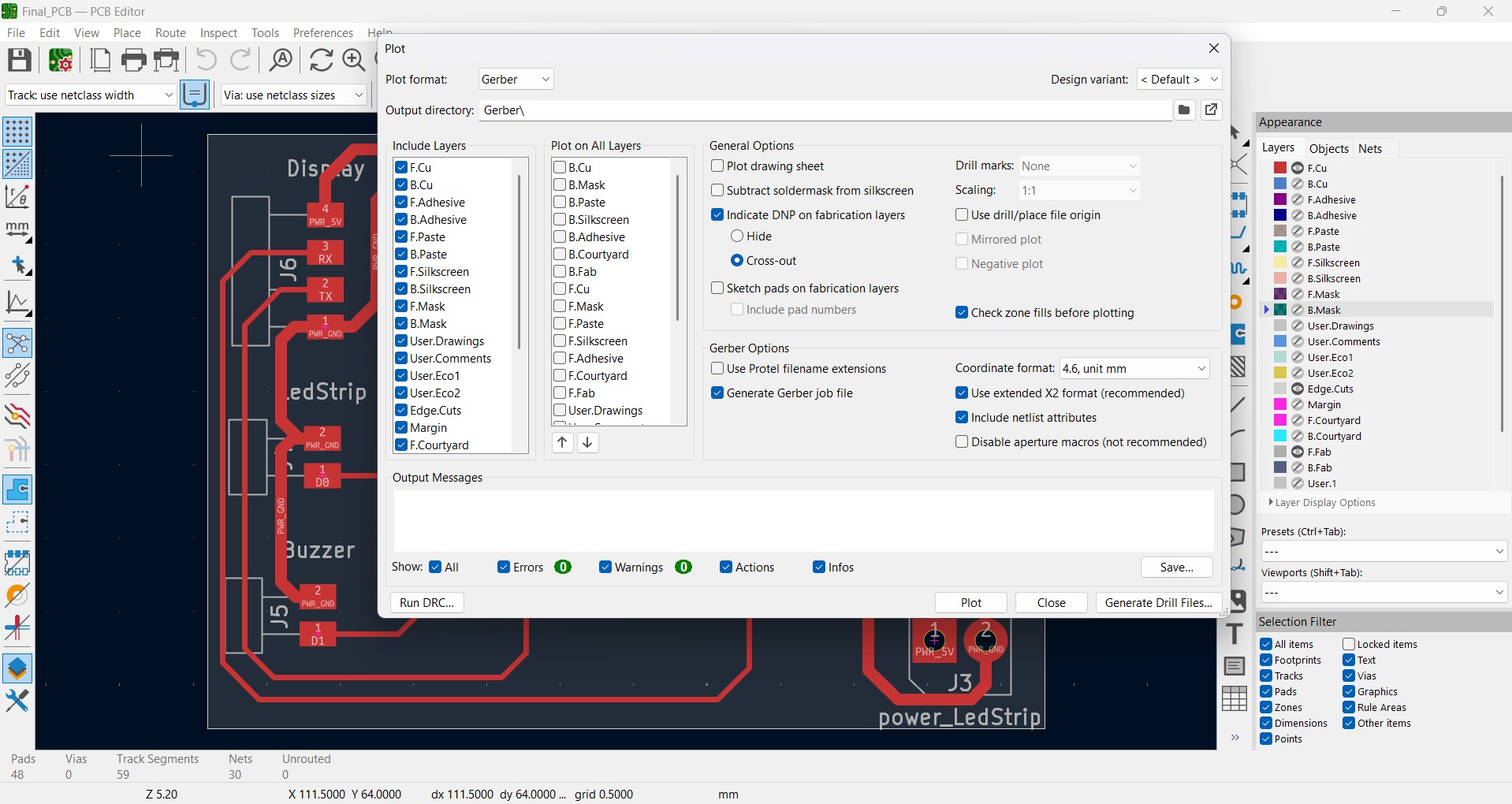
KiCad PCB Editor — Plot dialog with all layers selected for Gerber export. Format: Gerber. Output directory: Gerber\. Coordinate format: 4.6, unit mm. Extended X2 format and netlist attributes enabled.
Step 2 — Convert Gerber Files to PNG
gerber2png.fablabkerala.in
Mods does not read Gerber files directly — it works from PNG images. I used Gerber2PNG to convert the Gerber files into high-resolution PNG images. Two separate images are needed: one for the traces and one for the outline.For the traces image: I enabled only the Top layers — Trace and Pads — and clicked Generate PNG. I saved the file.
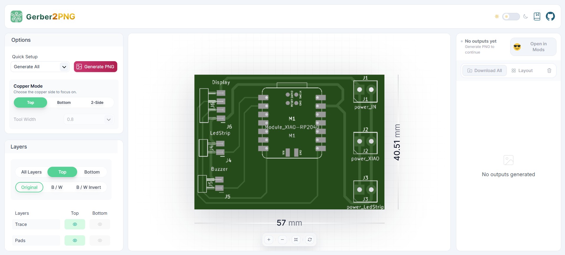
Gerber2PNG — Top layer in Original color mode showing all traces and pads. Board size: 57 × 40.51 mm.
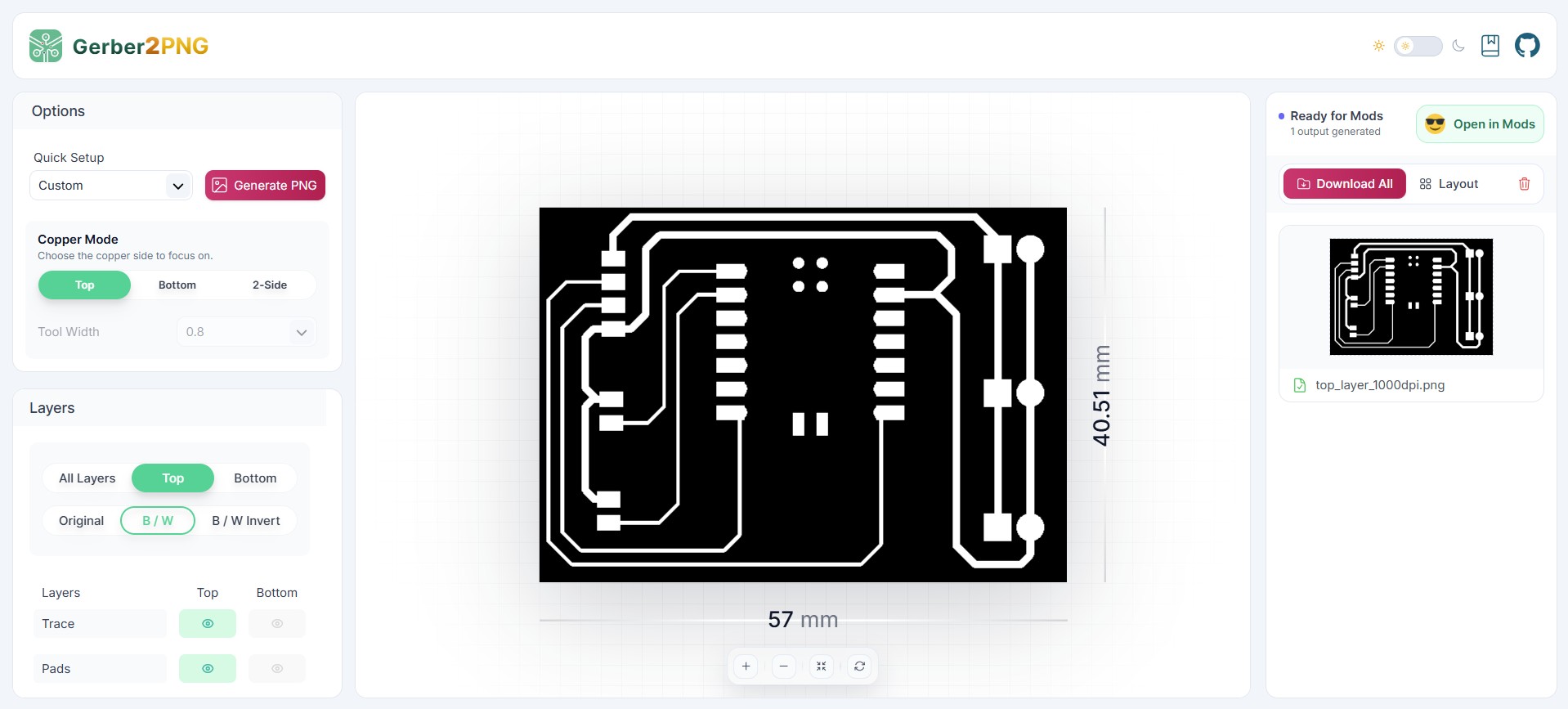
The same board in B/W Invert mode — white traces on black background. This is the format Mods requires. Downloaded as
top_layer_1000dpi.png.For the outline: I enabled only the Outline layer and set Canvas Background to White, producing a black board perimeter on a white background.
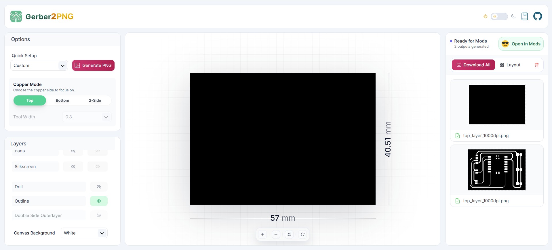
Outline PNG — only the Edge.Cuts layer enabled, Canvas Background set to White. A black rectangle on white representing the board perimeter (57 × 40.51 mm). This image is inverted before use in Mods.
Step 3 — Generate NC Toolpath Files in Mods
modsproject.org → Programs → Machines → Carvera → mill 2D PCB
With both PNG files ready I opened Mods and selected the Carvera → mill 2D PCB program. Mods is a browser-based CAM tool that converts PNG images into G-code toolpath files (.nc) for the Carvera.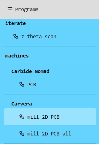
Mods program selector — Programs → Machines → Carvera → mill 2D PCB selected. This program generates the dual-tool isolation and outline toolpaths for the Carvera.
I loaded the traces PNG into the Traces image block. The full Mods canvas connects four sections: Traces image, Exterior image, the central Calculate block (mill dual-tool 2D), and the Tabs and save file blocks.
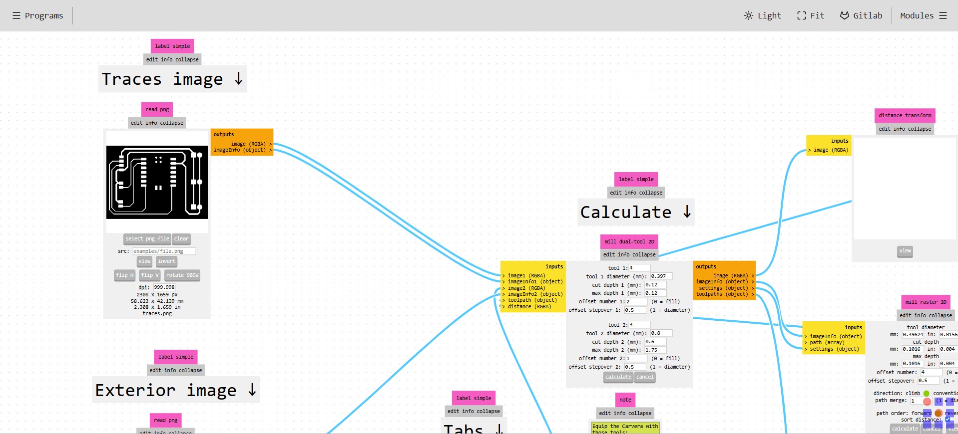
The complete Mods workflow canvas. Traces PNG (top-left) and outline PNG (bottom-left) feed into the central mill dual-tool 2D Calculate block. The Tabs block adds hold-down bridges. The save file blocks (right) generate the .nc downloads.
I used the default values and verified that the tool slots on the machine match the positions indicated in Mods. The Calculate block has settings for two tools:
Tool 1 — Fine isolation bit (1/64" / 0.4 mm), ATC slot 4:
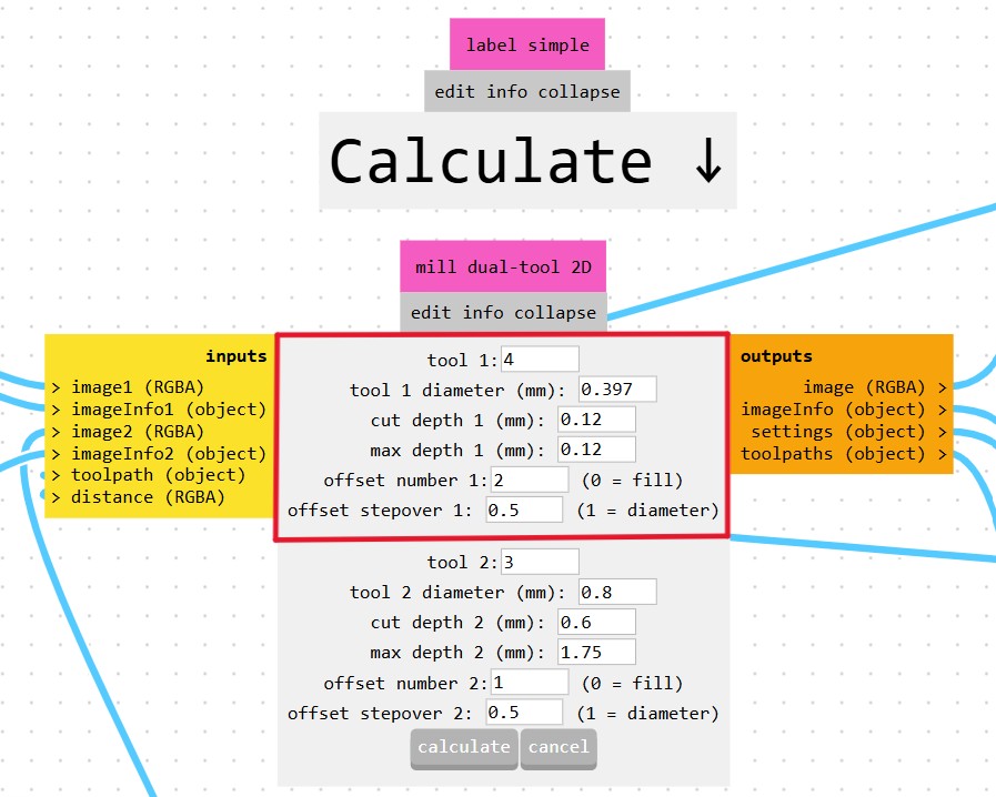
Tool 1 settings — Tool number: 4 (Carvera ATC slot). Diameter: 0.397 mm (≈1/64"). Cut depth: 0.12 mm. Max depth: 0.12 mm. Offset number: 2. Offset stepover: 0.5. This fine bit mills the isolation channels around every trace and pad.
Tool 2 — Outline bit (1/32" / 0.8 mm), ATC slot 3:
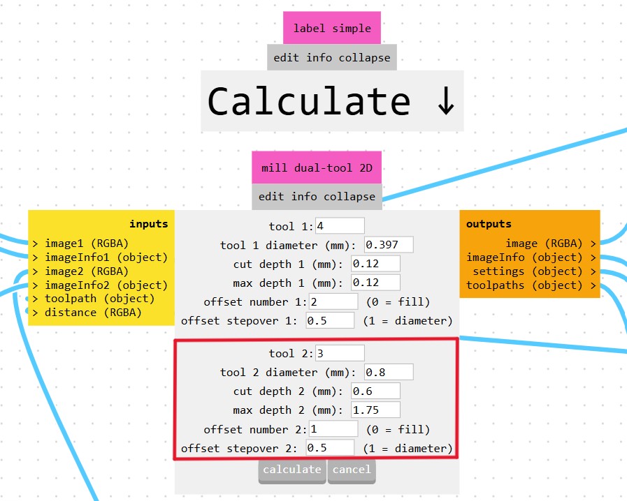
Tool 2 settings — Tool number: 3 (Carvera ATC slot). Diameter: 0.8 mm (≈1/32"). Cut depth: 0.6 mm per pass. Max depth: 1.75 mm (full board thickness). Offset number: 1. This bit cuts the board perimeter through the full FR4 thickness in multiple passes.
I clicked Calculate and verified the toolpaths in the 3D viewer:
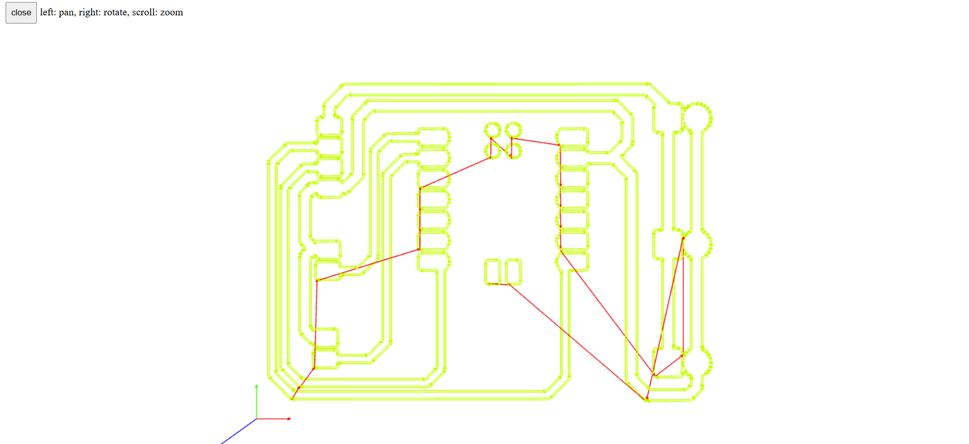
Mods 3D preview — traces isolation pass. Yellow-green lines are cutting moves; red lines are rapid moves (tool lifted above surface).
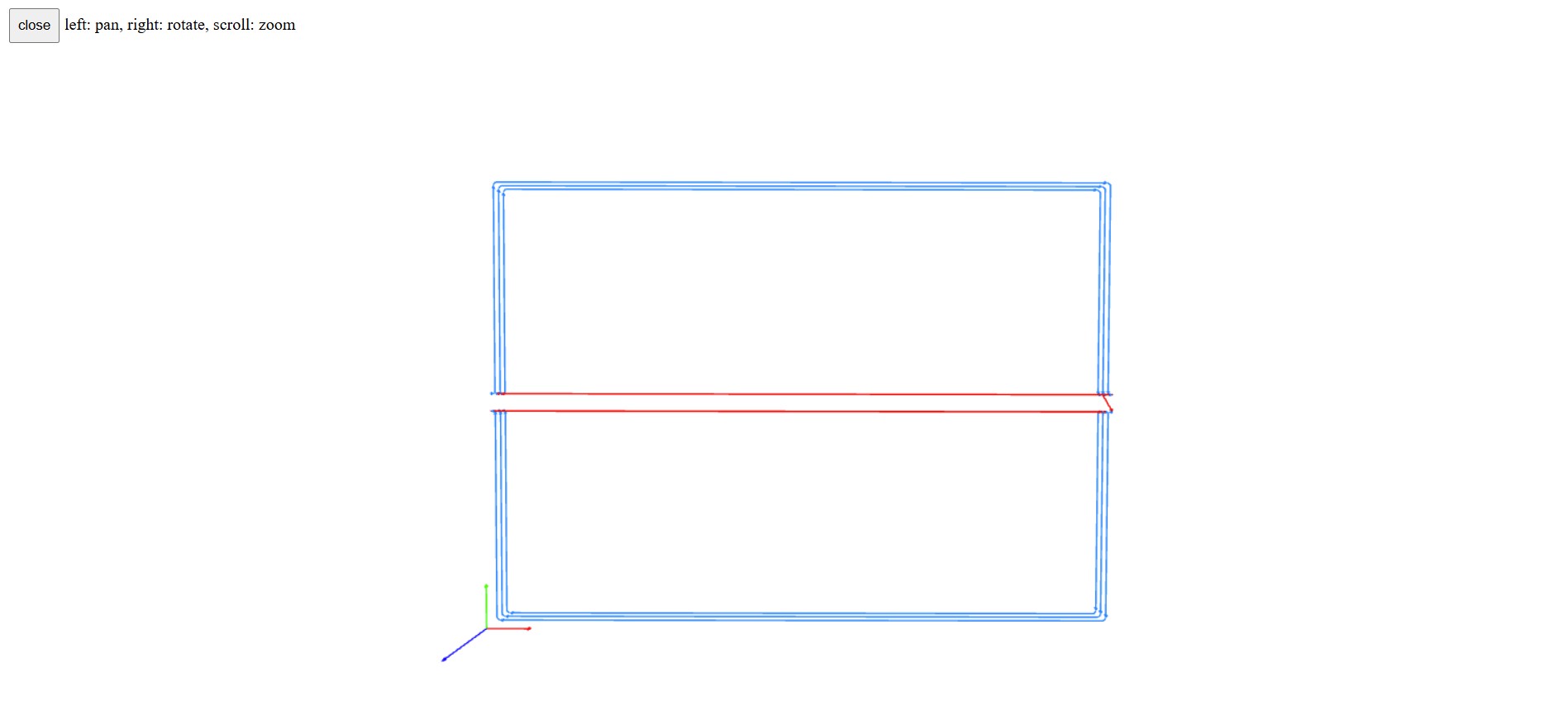
Mods 3D preview — outline cutout. Blue lines show the perimeter cut. The small gap is the tab — an uncut bridge that holds the board in place until the job finishes.
I saved the traces toolpath using the save file block:
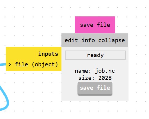
Mods save file block —
job.nc, 2028 bytes, status "ready". Each toolpath (traces and outline) is saved as a separate .nc file.Then I repeated the process for the outline from the Exterior image section. The image must be inverted. I used the default configuration and saved the generated file.
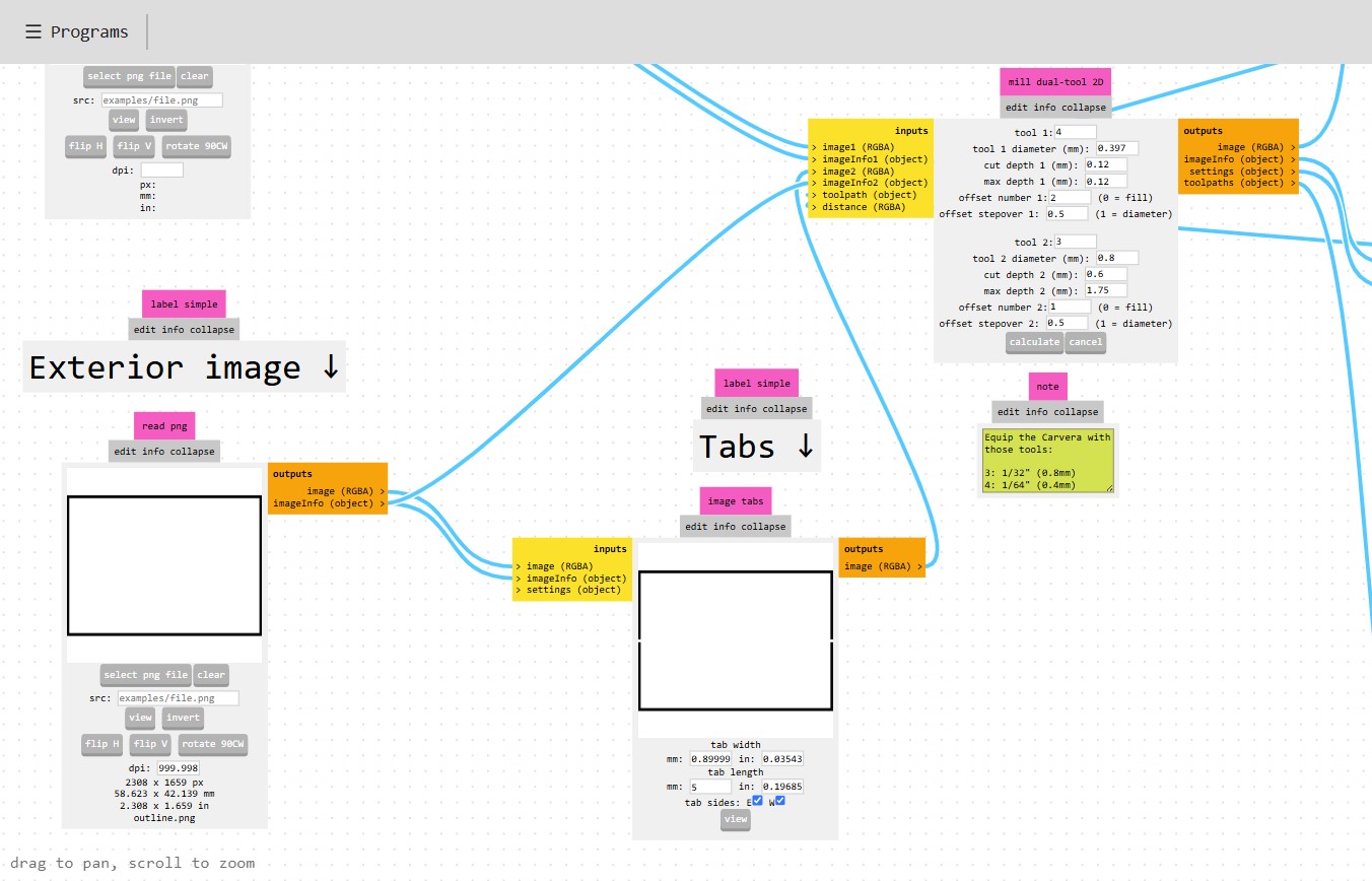
Exterior image section — outline PNG loaded, image inverted. The Tabs block (below) is configured: tab width 0.9 mm, tab length 5 mm, tabs on E and W sides. Tabs hold the board to the sheet during the final perimeter cut.
Step 4 — Load Files into Carvera Controller
I loaded the NC files into the Carvera Controller desktop application one at a time, and verified the toolpaths in the 3D preview before running the machine.
Traces NC file:
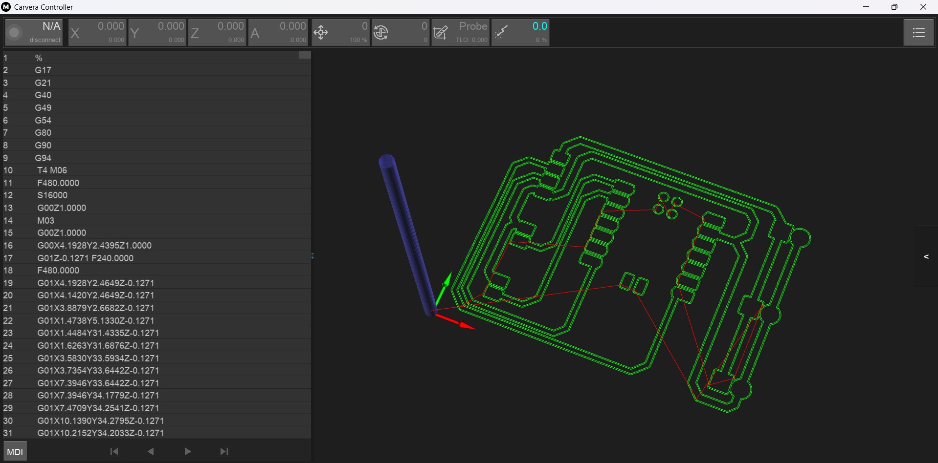
Carvera Controller — traces NC file loaded. The 3D preview (right) shows the green isolation toolpath. The G-code listing (left) selects Tool 4 (T4 M06) — the 1/64" bit — at 16,000 RPM (S16000), starting isolation passes at Z −0.1271 mm.
Outline NC file:
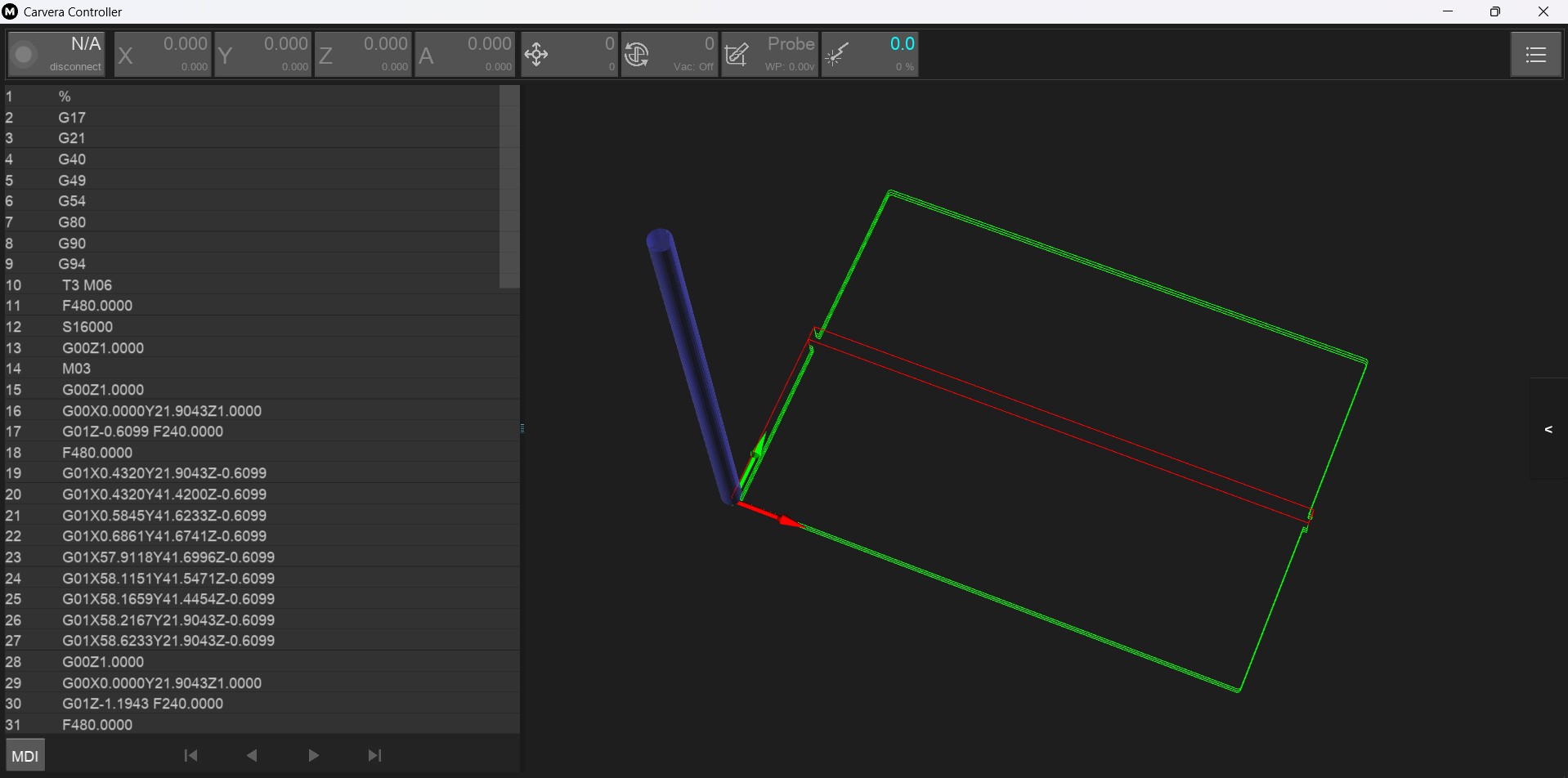
Carvera Controller — outline NC file loaded. The 3D preview shows the rectangular perimeter cut in blue. Tool 3 (T3 M06) — the 1/32" bit — makes multiple passes at 0.6 mm per pass until the full 1.75 mm board thickness is reached.
Step 5 — Milling the PCB
With the copper-clad board secured on the Carvera bed and Z-zero set to the board surface using the auto-leveling probe, I ran the traces NC file first. The Carvera then automatically changed to Tool 3 via the ATC and ran the outline NC file to cut the board free from the sheet.
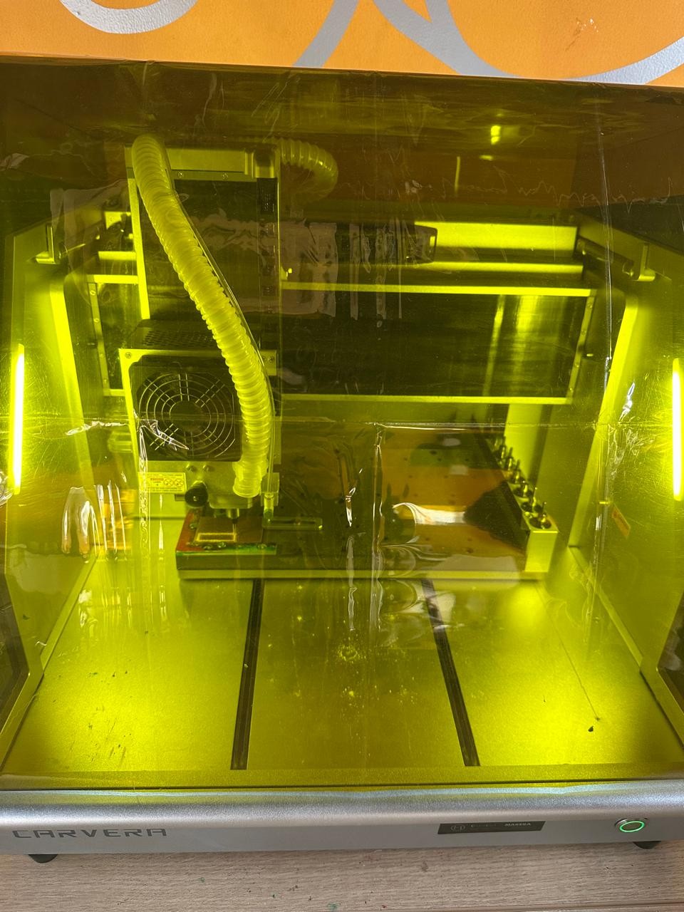
The Makera Carvera at the ESAN Fab Lab milling the pitch timer PCB. The enclosed work area is illuminated by the machine's integrated LED strip. The spindle is executing the isolation passes over the copper-clad board secured on the bed.
Step 6 — Result: Milled PCB
After both toolpaths completed, the board was removed from the sheet (the tab was cut with a blade) and inspected. The isolation channels between traces are clearly visible and no copper bridges or broken traces are present.
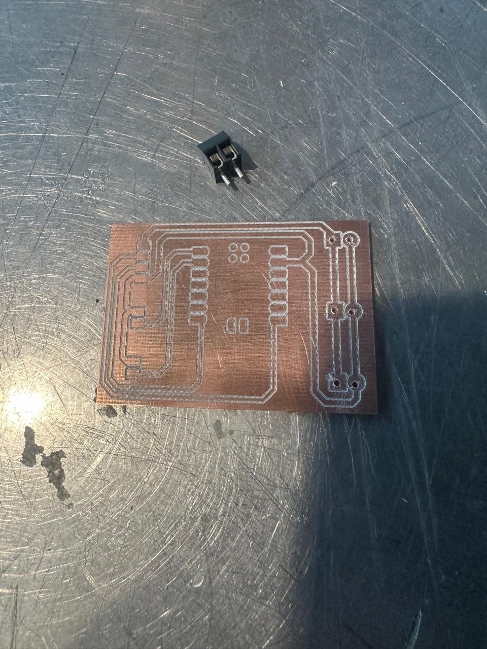
The freshly milled pitch timer PCB on the workbench, with a connector placed above for scale. Isolation channels are clean and well-defined. All footprint pads are correctly formed.
Step 7 — Soldering, Assembly and Testing
With the board milled and inspected, I soldered all components: the XIAO RP2040 module, the connectors for the LED strip (J4), buzzer (J5), and Nextion display (J6), and the three 5V power screw terminals (J1, J2, J3).
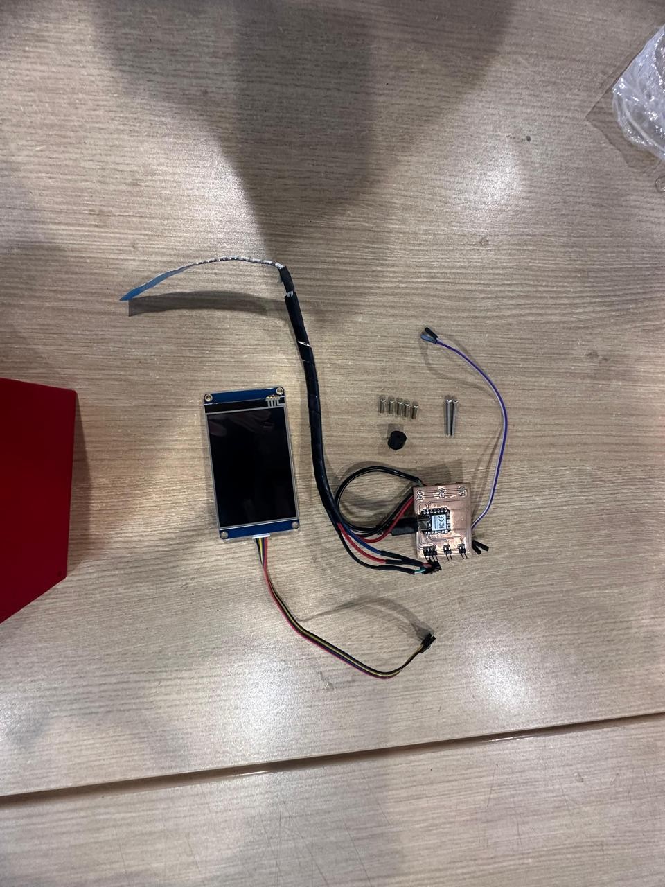
The assembled pitch timer PCB with all components soldered: the XIAO RP2040 module, the Nextion display connector with color-coded wires, the LED strip connector, the buzzer connector, and the 5V power screw terminals. All output devices are ready to connect.
I then connected all three output devices to the board and uploaded the firmware to the XIAO RP2040 using the Arduino IDE.
The full pitch timer system connected: the Nextion 3.5" HMI touch display (left, off) and the milled PCB (right) with the XIAO RP2040, all connectors, and wiring to the LED strip, buzzer, and display. The system is ready to be powered and programmed.
The firmware uses a non-blocking state machine with
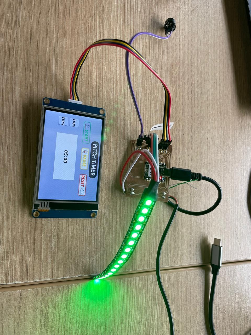
millis()to coordinate all three output devices simultaneously:Output Device Protocol XIAO Pin Function Nextion NX4832T035_011 HMI display UART — Serial1, 9600 baud TX / RX Shows countdown MM:SS; sends touch commands (START, PAUSE, RESET, PRESET:3/4/5) WS2812B LED strip — 16 LEDs NeoPixel single-wire D0 Green → Yellow → Red as time decreases; solid Red at finish Passive buzzer PWM tone — 2 kHz D1 5-second alert tone when countdown reaches zero The video below shows the complete system running — the Nextion display counting down, the LED strip changing color, and the buzzer triggering at zero:
pitch timer running: the Nextion 3.5" HMI display shows the PITCH TIMER interface with START, PAUSE, and RESET touch buttons and the MM:SS countdown. The WS2812B LED strip responds in real time as the countdown progresses and the XIAO RP2040 receives touch commands from the display over UART.
Reflections
This week made the connection between digital design and physical fabrication concrete and irreversible. Once you mill copper off a board there is no undo — which forces a precision of thinking at the design stage that is genuinely different from iterating on a screen. Every trace width, pad clearance, and component placement has a consequence in copper and FR4 that you live with.
The Makera Carvera's automatic tool change was impressive in practice. Switching from the fine 1/64" isolation bit to the 1/32" outline bit happened automatically and cleanly, without any manual intervention. For a board as intricate as the pitch timer PCB, that automation is what makes in-house milling a realistic production method and not just a demonstration.
The most striking insight was the compression of the value chain. The full path from schematic to physically running board — KiCad design, Gerber export, Gerber2PNG conversion, Mods toolpath generation, Carvera milling, soldering, and firmware upload — is achievable in a single working day in a Fab Lab. That speed of iteration is a genuine competitive advantage for early-stage hardware ventures.
Resources
XIAO_code_01.ino — pitch timer firmware (Arduino) final_project_hmi.tft — Nextion HMI display fileLicensed under CC BY-NC-SA 4.0 — © Marita Chang