Make (design+mill+assemble) something big (~meter-scale)
• extra credit: don't use fasteners or glue
• extra credit: include curved surfaces
• extra credit: use three-axis toolpaths
Group assignment
- Do your lab's safety training
- Test runout, alignment, fixturing, speeds, feeds, materials, and toolpaths for your machine
What I knew beforehand
Before this week I had never operated a CNC router of any kind. My experience with digital fabrication was limited to the laser cutter and 3D printer — both of which are much more forgiving machines. The CNC router is different: it is large, loud, and powerful, the bit can break or the material can fly if something goes wrong, and the software workflow is significantly more complex.
What I did understand was the logic of a production process: design constraints flow downstream into fabrication decisions, and every choice about geometry, material, and tooling has cost and quality implications. That systems-level thinking helped me approach the week's assignment deliberately rather than reactively.
I chose to design a bench — compact, functional, and structurally interesting — and to personalize it with Snoopy imagery, because the character already featured in my final project (PitchLight) and because it gave me a chance to practice multiple toolpath types on a single piece.
This assignment was completed in November 2025. Having learned the ShopBot workflow during the regular cycle, I returned to it with a clearer design goal: a Snoopy-themed bench using press-fit joinery, V-carve engraving, and silhouette cutouts. The project was more ambitious than a standard first-time CNC assignment, and completing it outside the regular weekly schedule reflected the reality of continuing student life. Group assignment I worked with my colleague Jhasmin Ayala
The bench consists of three component types cut from a single sheet of 12 mm MDF:
Top (circular) — 500 mm diameter round surface with a V-carved Snoopy-on-his-doghouse illustration and a pocket slot cross pattern for the legs.
Side panels (×2) — each leg panel has a Snoopy silhouette cut through as a decorative window, a V-carved "SNOOPY" text, and the cross-slot joint that locks with the top.
The assembly is tool-free: the two side panels interlock with each other and with the top through cross-shaped slots. No screws, no glue — the joints hold everything in place through friction and geometry, following the press-fit principle used throughout Fab Academy.
A press-fit or slot-and-tab assembly means the parts are designed to snap or slide together like a puzzle. The slot width must match the actual thickness of the material — not the nominal thickness. Always measure your sheet with a caliper before designing, because 12 mm MDF often measures 11.7–11.9 mm in practice.
Design Files
The bench was designed in Fusion 360 and exported as DXF files for import into VCarve Pro. The files went through several versions as I iterated on the slot dimensions and the Snoopy vector:
File
Part
Version notes
Top.dxf
Top surface
Initial version
Top_v3.dxf
Top surface
Corrected slot width and fillet adjustments
Top_v4.dxf
Top surface
Final version with Snoopy engraving area
Side_01_v3.dxf
Side panel 1
Snoopy silhouette window + SNOOPY text
Side_02_v2.dxf
Side panel 2
Mirror of Side 01 with matching slots
snoopy_vector.svg
Snoopy silhouette
Source vector for the cut-through window
Snoopy1_svg.svg
Snoopy on doghouse
Source vector for V-carve engraving on top
Snoopy2_svg.svg
Snoopy variant
Alternative vector tested
Software: VCarve Pro (ShopBot Edition)
VCarve Pro is the CAM software used to translate 2D vector geometry into machine toolpaths. It reads DXF or SVG files, allows you to assign different operations to different vectors, and outputs a G-code file (.sbp for ShopBot) that the machine executes.
The workflow in VCarve follows this sequence for every job:
Set up the job dimensions (material size and thickness)
Import the DXF/SVG files
Add T-Bone fillets to all internal corners
Create toolpaths for each operation type
Preview the simulation
Save the toolpath file (.sbp)
Step 1 — T-Bone Fillets: Solving the Round-Bit Problem
1Why internal corners need special treatment A CNC router bit is cylindrical — it is physically impossible for it to cut a perfectly sharp 90° internal corner. The bit always leaves a rounded radius equal to half its diameter. If your slot is designed to receive a flat-edged part, the rounded corner will prevent the part from fitting flush.
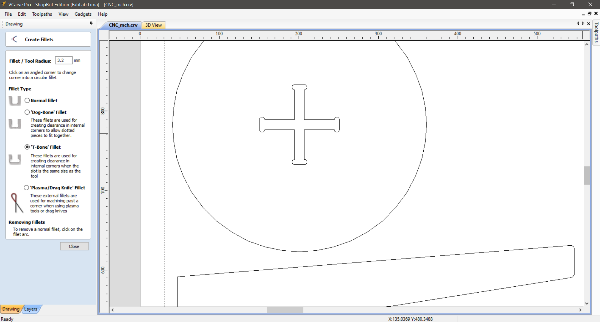
The solution is to add a T-Bone fillet (or Dog-Bone fillet) at each internal corner: a small circular cutout that extends the corner beyond the slot edge, giving the mating part clearance to seat fully. In VCarve Pro, go to Edit → Fillets, select 'T-Bone' Fillet, set the radius to match the bit radius (3.2 mm for a 1/4" bit), and click each internal corner of the slot geometry.
VCarve Pro showing the T-Bone Fillet tool applied to the cross-shaped slot on the bench top. Fillet radius is set to 3.2 mm (half the 1/4" bit diameter). The T-Bone option is selected because the slot width equals the tool width — normal fillets would remove material outside the slot.
Dog-Bone fillets extend the corner diagonally outward; T-Bone fillets extend it along one wall of the slot. Use T-Bone when the slot is only slightly wider than the bit. Both are invisible in the assembled piece because they sit inside the joint — you only see them if you look directly into the slot from above.
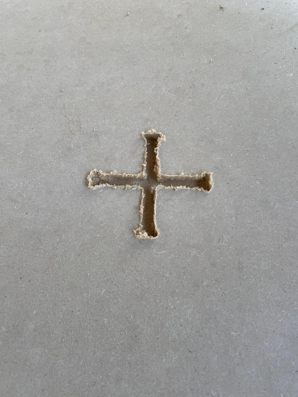
Close-up of the finished cross slot cut into the bench top. The four T-Bone fillets are visible at each internal corner — those small rounded extensions ensure the side panels can slide fully into the joint without the router's rounded kerf blocking them.
Step 2 — Pocket Toolpath: Clearing the Slot Interior
2Pocket toolpath for the cross slot
The cross-shaped slot on the top is a Pocket toolpath — it removes material from inside a closed vector to a set depth, rather than cutting all the way through. This creates the mortise that the side panels' tenon tabs will fit into.
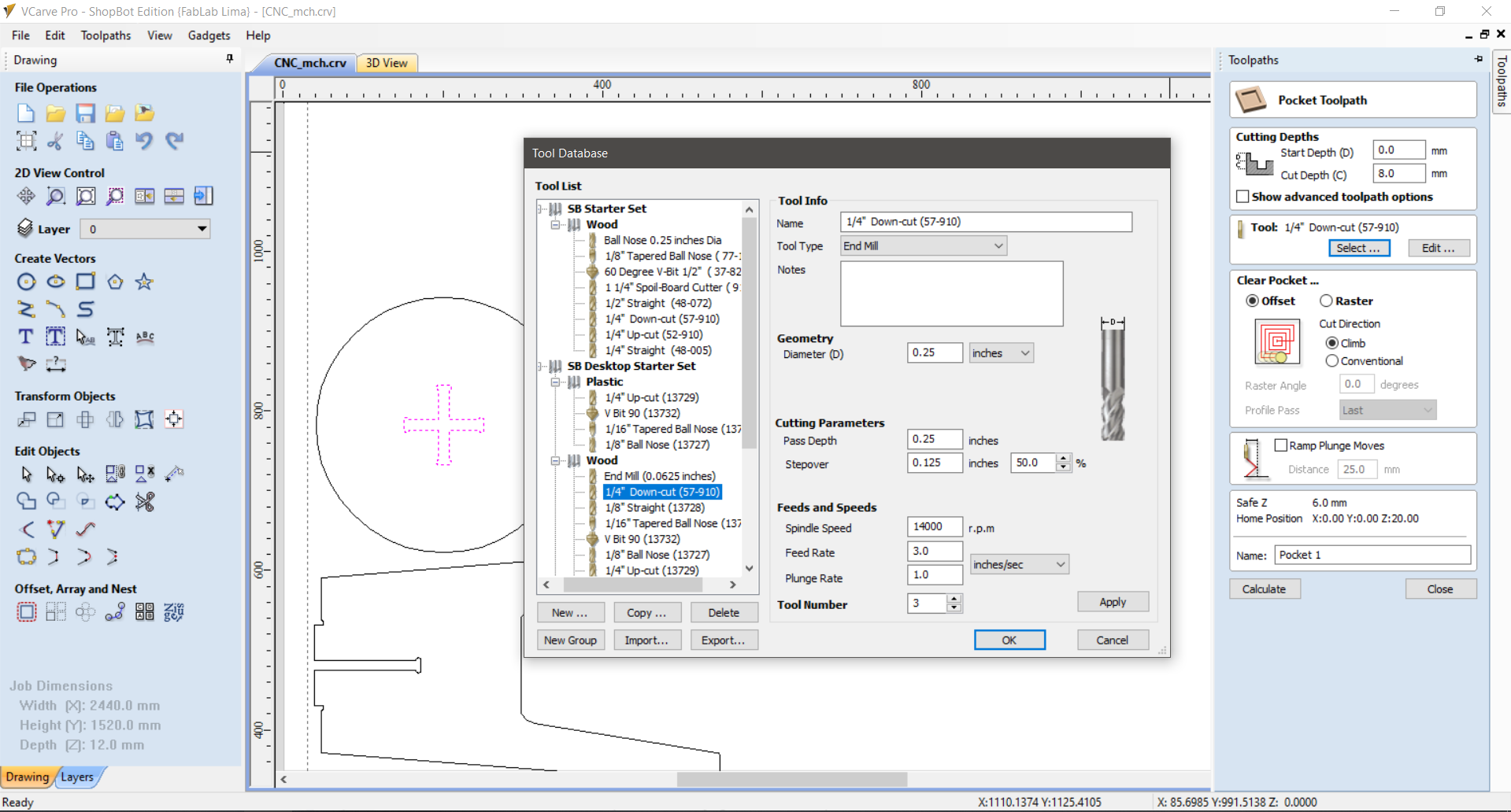
Settings used: Tool: 1/4" Down-cut end mill (57-910) · Cut Depth: 8.0 mm (not full thickness, to preserve the top surface) · Stepover: 50% · Feed Rate: 3.0 in/sec · Spindle: 14,000 RPM.
VCarve Pro Tool Database with the 1/4" Down-cut (57-910) end mill selected for the Pocket toolpath. Cut depth is 8.0 mm. The down-cut geometry pushes MDF fibres downward, giving a cleaner top surface finish compared to an up-cut bit. Feed rate: 3.0 in/sec, Spindle: 14,000 RPM.
3Inside profile for the Snoopy window in the side panels
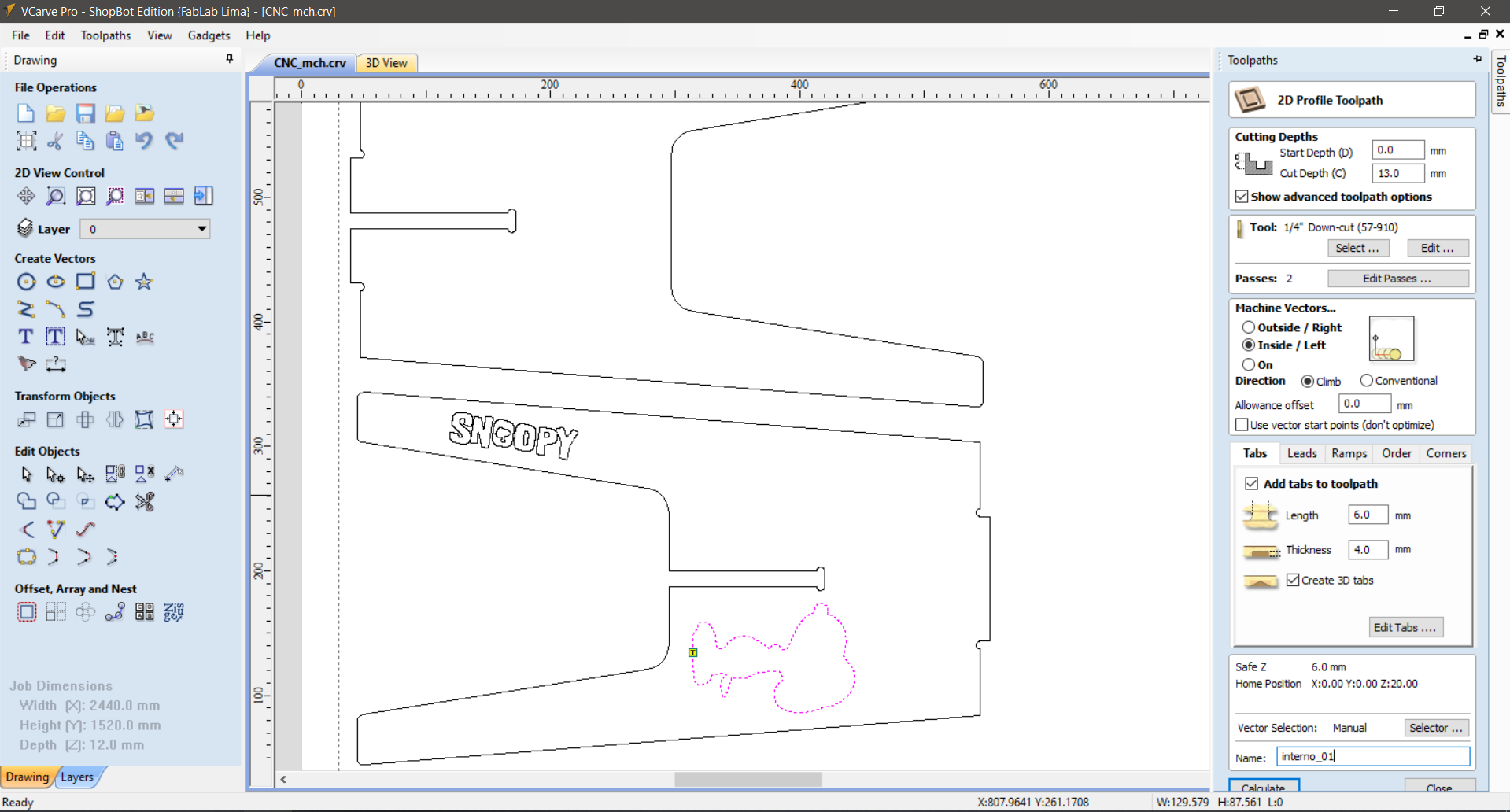
The silhouette on each side panel is a cut-through profile on the Inside/Left of the vector — the bit follows the inner edge of the outline, cutting the Snoopy shape out of the panel completely. The result is a decorative open window through which light and the background are visible.
Settings: Tool: 1/4" Down-cut (57-910) · Cut Depth: 13.0 mm (full material thickness) · Passes: 2 · Tabs: enabled (6 mm length × 4 mm thick) to prevent the cut-out piece from moving before the job is complete.
VCarve Pro — 2D Profile Toolpath set to Inside/Left for the Snoopy silhouette cut. Cut depth: 13.0 mm (full thickness). The Tabs panel is open on the right: 6 mm length, 4 mm thickness, 3D tabs enabled. Tabs are small uncut bridges that keep the piece from shifting during the last pass.
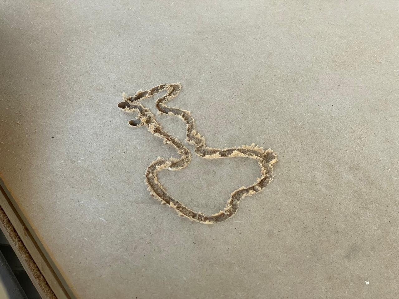
The first Snoopy silhouette profile cut in MDF. The overall shape is correct but the edges show some tearing at narrow areas of the vector. This was the version that revealed the vector had too many tight curves for the 1/4" bit — which led to switching to a simplified vector for the final cut.
Step 4 — V-Carve Toolpath: Engraving the Snoopy Illustration and Text
4V-Carve for the Snoopy illustration on the bench top
The Snoopy-on-his-doghouse illustration on the round top surface is a V-Carve / Engraving toolpath. Unlike a profile (which cuts a fixed width), a V-bit cuts deeper in wider areas and shallower in narrow areas, producing a variable-depth engraving that closely follows the vector shapes — ideal for fine details and text.
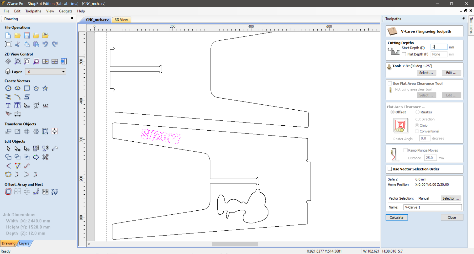
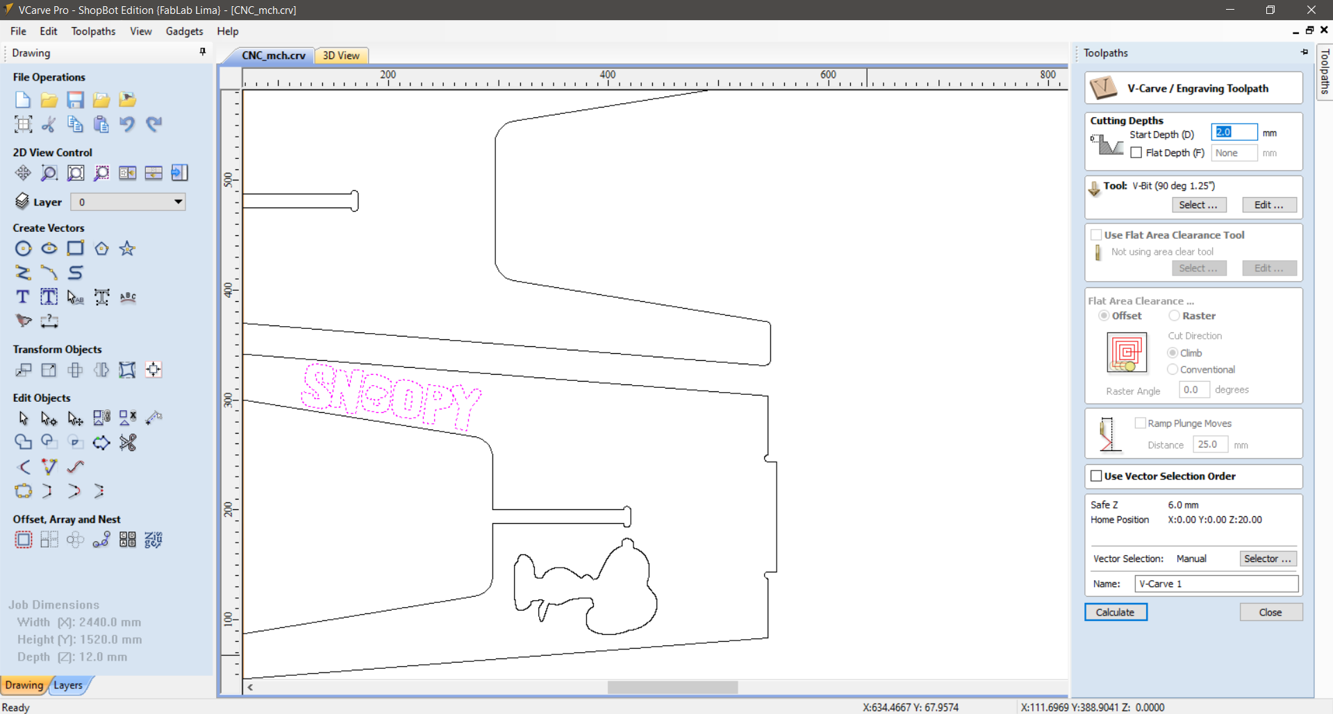
Settings: Tool: V-Bit 90° 1.25" · Start Depth: 2.0 mm · Flat Depth: None (full V-carve).
The same V-Carve toolpath was also applied to the "SNOOPY" text on the side panels, giving the lettering a clean chiseled appearance.
V-Carve / Engraving Toolpath panel with the Snoopy illustration selected (shown in pink dashes on the canvas). Tool: V-Bit 90° 1.25". Start depth: 2 mm. No flat depth — pure V-carve follows the vector contours.
The same V-Carve toolpath applied to the "SNOOPY" text vector on the side panel. The text is shown highlighted in pink. Start depth: 2.0 mm. The V-bit produces the characteristic tapered groove that gives engraved text its clean, sharp-edged look.
Step 5 — Profile Toolpath (Outside): Cutting the Outer Perimeter
5External profile to cut all parts free from the sheet
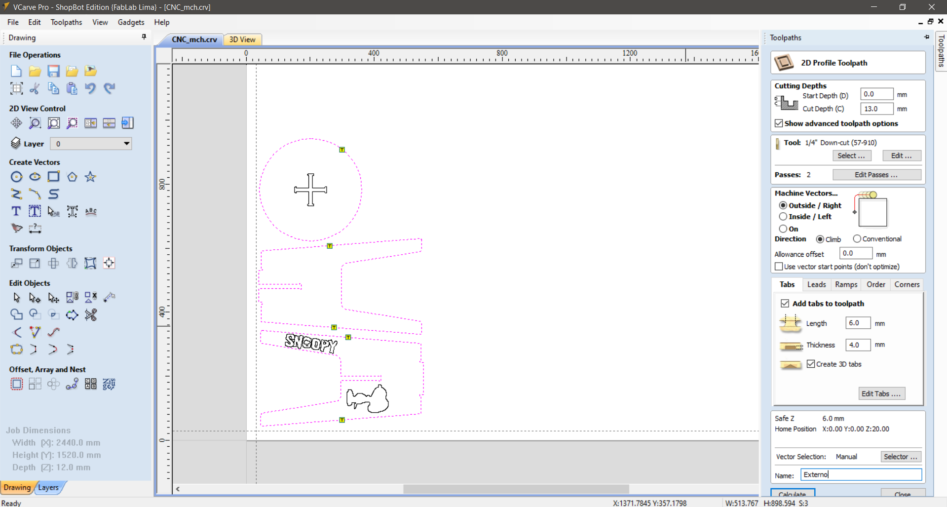
The final toolpath in the sequence is the Outside/Right profile that cuts the outer perimeter of every part — the circular top and the two side panels — all the way through the 12 mm MDF. This is always the last toolpath to run; if you ran it first, the parts would come loose before the pockets and engravings were complete.
Settings: same 1/4" Down-cut bit · Cut Depth: 13.0 mm · 2 passes · Tabs enabled.
VCarve Pro — External (Outside/Right) 2D Profile Toolpath. All outer perimeters are shown selected in pink dashes: the circular top, both side panels, and the SNOOPY text outline. Cut depth: 13.0 mm (full thickness). Tabs are enabled with 6 mm length × 4 mm thickness to hold parts in place during the final pass.
⚠️ Toolpath order matters: Always run interior operations first (pockets, internal profiles, engravings) and the external cutout last. If you reverse this, the part becomes loose before the other operations are complete, which causes the bit to cut in the wrong position — or worse, the part moves suddenly and breaks the bit.
Machine Operation — ShopBot at the ESAN Fab Lab
The CNC router at the ESAN Fab Lab is a ShopBot PRS Alpha — a large-format 3-axis router with a cutting area of approximately 2440 × 1520 mm and a 12 mm-capable HSD spindle. Before running any job, the following preparation steps are mandatory.
1Safety equipment — non-negotiable The ShopBot requires: safety glasses (flying chips), ear protection (sustained noise above 90 dB), a dust mask (MDF dust contains formaldehyde resin), and gloves for material handling. The safety signs at the ESAN Fab Lab list these as mandatory — not optional. Never reach over the safety rail while the spindle is running.
2Securing the material The MDF sheet must be held flat and immobile during cutting. The ShopBot uses a vacuum table that holds the material through suction — the vacuum pump under the table draws air through the MDF fibres, pressing the sheet against the bed. Check that the sheet is fully sealed against the bed before starting. A sheet that lifts during cutting will cause a ruined job at best, a broken bit and damaged machine at worst.
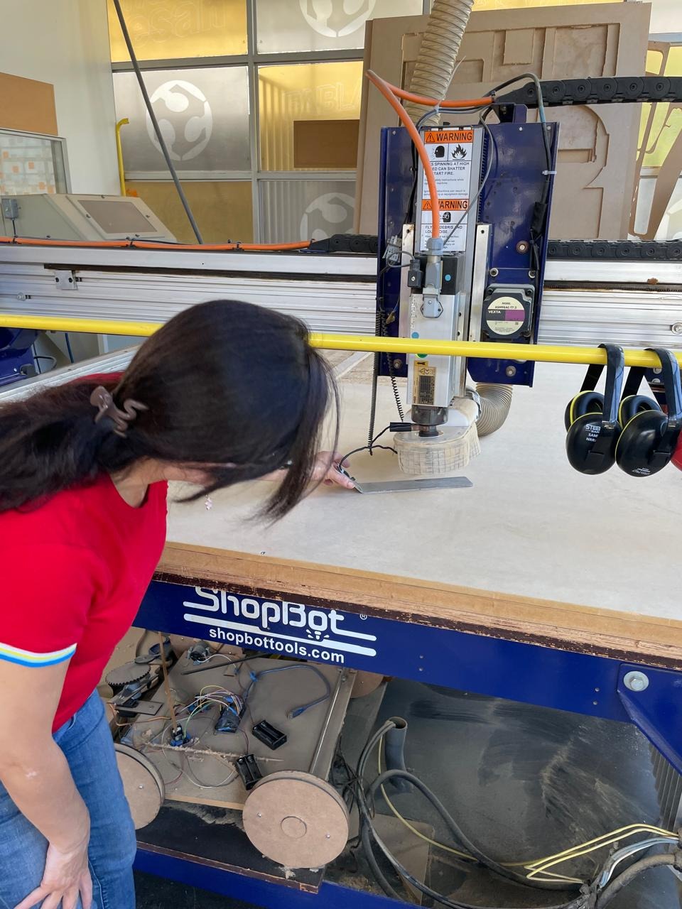
3Setting the Z-zero (material surface) Before running the job, the bit's Z-zero position must be set to the surface of the material. This is done by jogging the bit down until it barely touches the sheet and zeroing the Z-axis in ShopBot's control software. If Z-zero is wrong, the cut depths will be off — a Z that is set too low can drive the bit into the vacuum table bed.
Setting up the ShopBot at the ESAN Fab Lab — checking the Z-zero position before starting the job. The spindle is positioned over the material surface; the collet and dust skirt are visible. The ShopBot control computer is visible in the background.
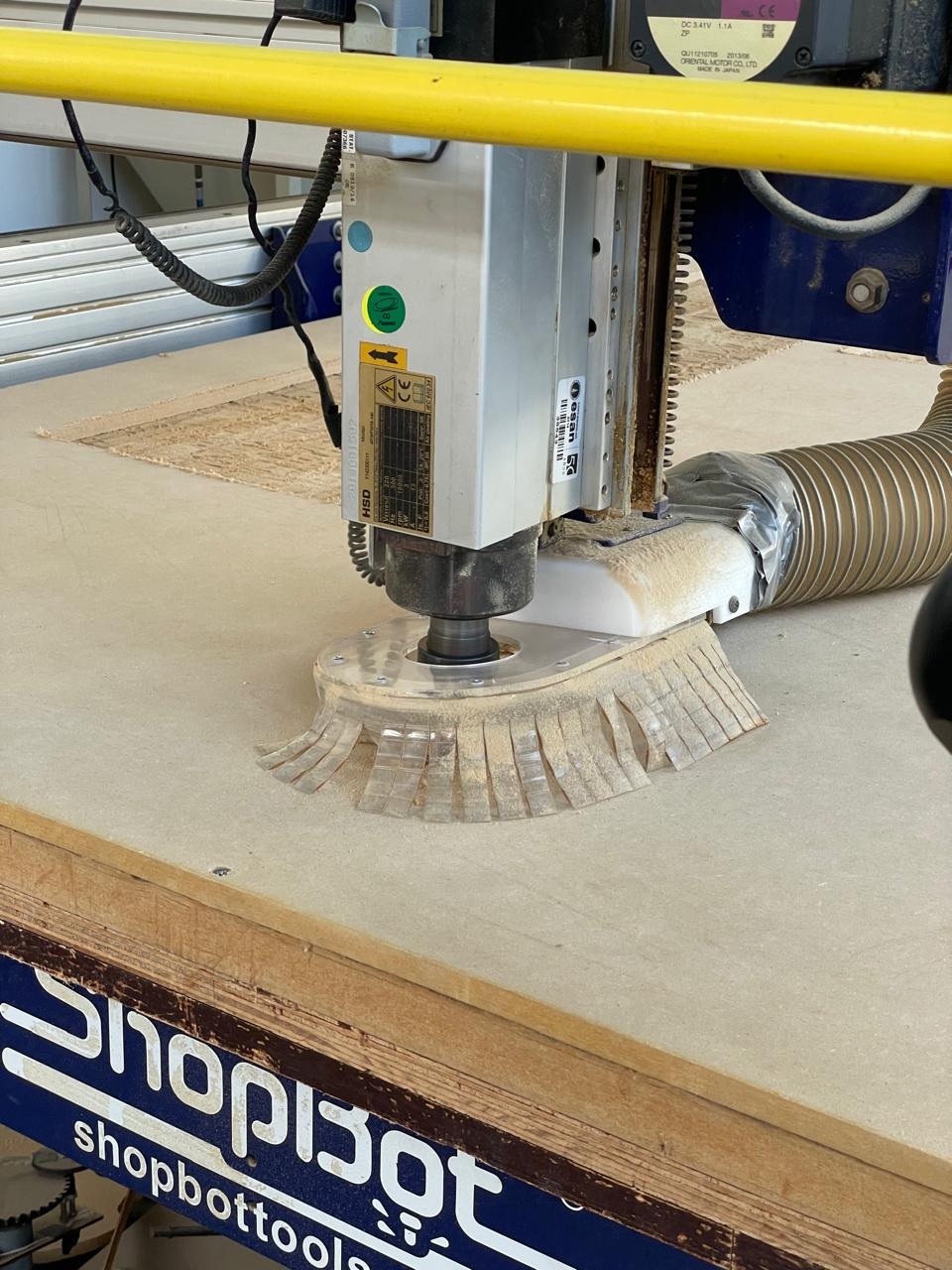
The ShopBot HSD spindle with the 1/4" down-cut bit installed and the dust collection skirt in position. The skirt captures the majority of MDF dust during cutting, directing it into the vacuum system. The MDF sheet is visible on the bed, held flat by the vacuum table.
4Running the job and monitoring Once the job starts, stay at the machine and watch. Never leave a running CNC job unattended. Know where the emergency stop button is before you start — on the ShopBot it is a large red button on the control box. If anything looks wrong (unusual sound, material movement, smoke), stop the job immediately.
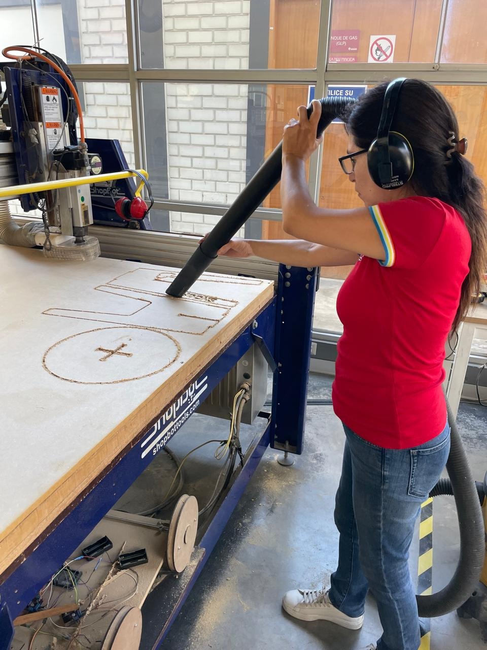
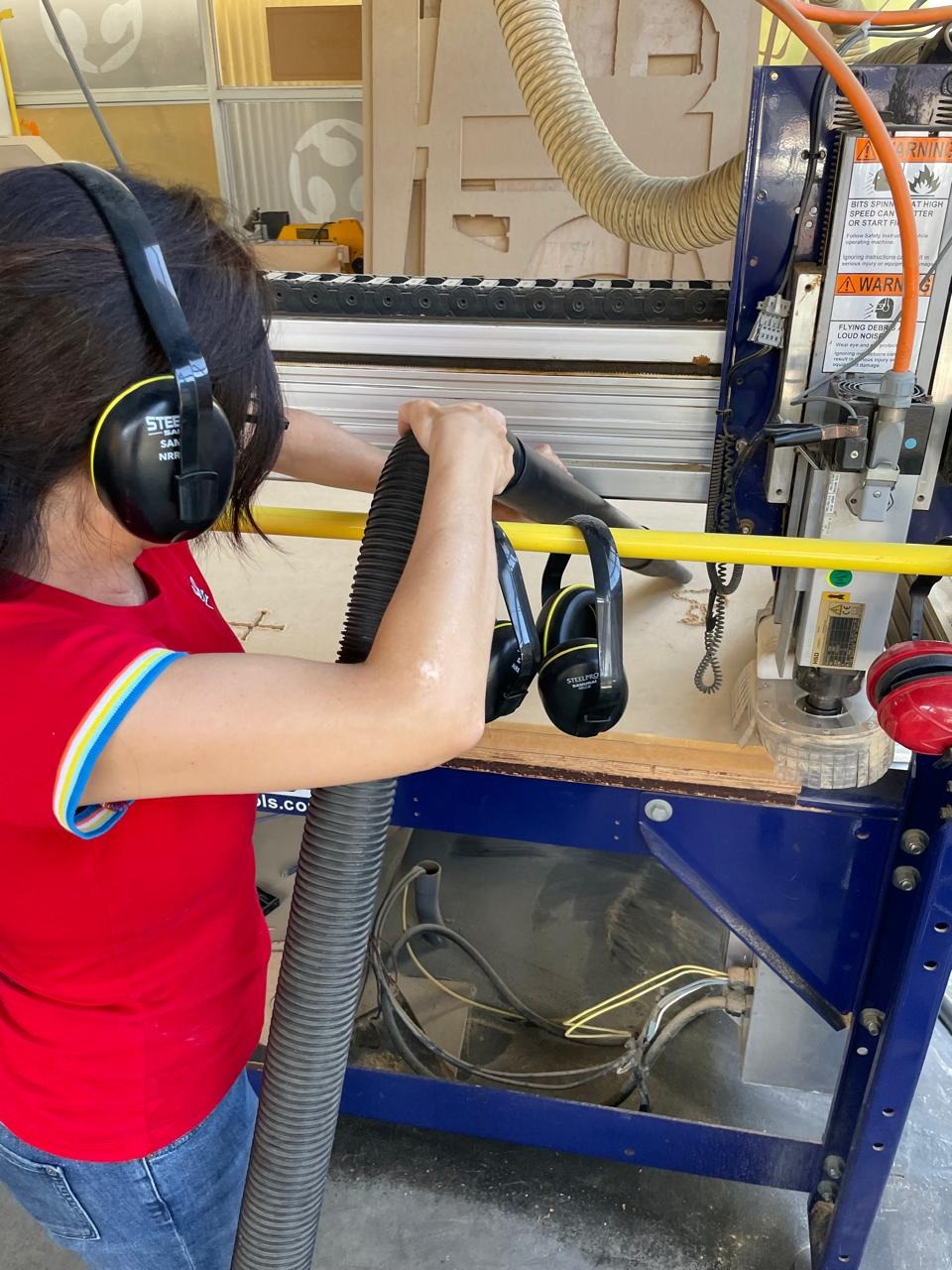
Between toolpaths, vacuuming MDF dust from the bed with ear protection and safety glasses on. Keeping the bed clean between passes lets you inspect the work-in-progress and confirms that the previous toolpath completed correctly before starting the next one.
Clearing MDF chips from the ShopBot bed with the shop vacuum. MDF dust is particularly fine and dense — it accumulates quickly and should be cleared between toolpath passes both to see the work clearly and to reduce dust inhalation risk.
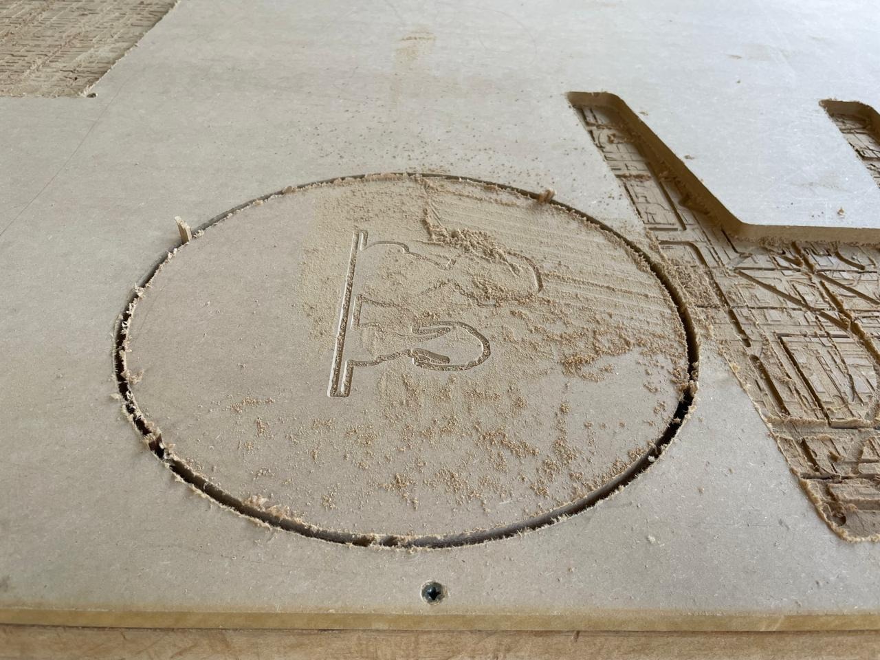
The bench top on the ShopBot bed after V-carving and pocket operations, with the circular perimeter profile cut visible. The V-carved Snoopy illustration is faintly visible through the MDF dust on the surface, and the cross-shaped pocket slot is machined into the center.
Post-Machining: Removing Tabs and Assembly
After the machine finished all toolpaths, the parts were still attached to the sheet by the tabs. Removing them carefully without damaging the edges is an important step that beginners often underestimate.
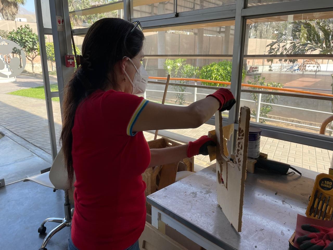
Post-machining work: removing tabs and cleaning up the edges. A dust mask is essential here — MDF dust is more dangerous when sanded by hand than when cut by machine, because the particles are finer. Gloves protect against splinters from the tab removal process.
Once the tabs were removed and the edges cleaned up, the three parts slot together with light hand pressure. No tools required.
The finished bench
First look at the assembled bench after removing tabs and fitting the parts together. The V-carved Snoopy-on-his-doghouse illustration is clearly visible on the circular top, along with the cross slot that locks the two side panels in place.
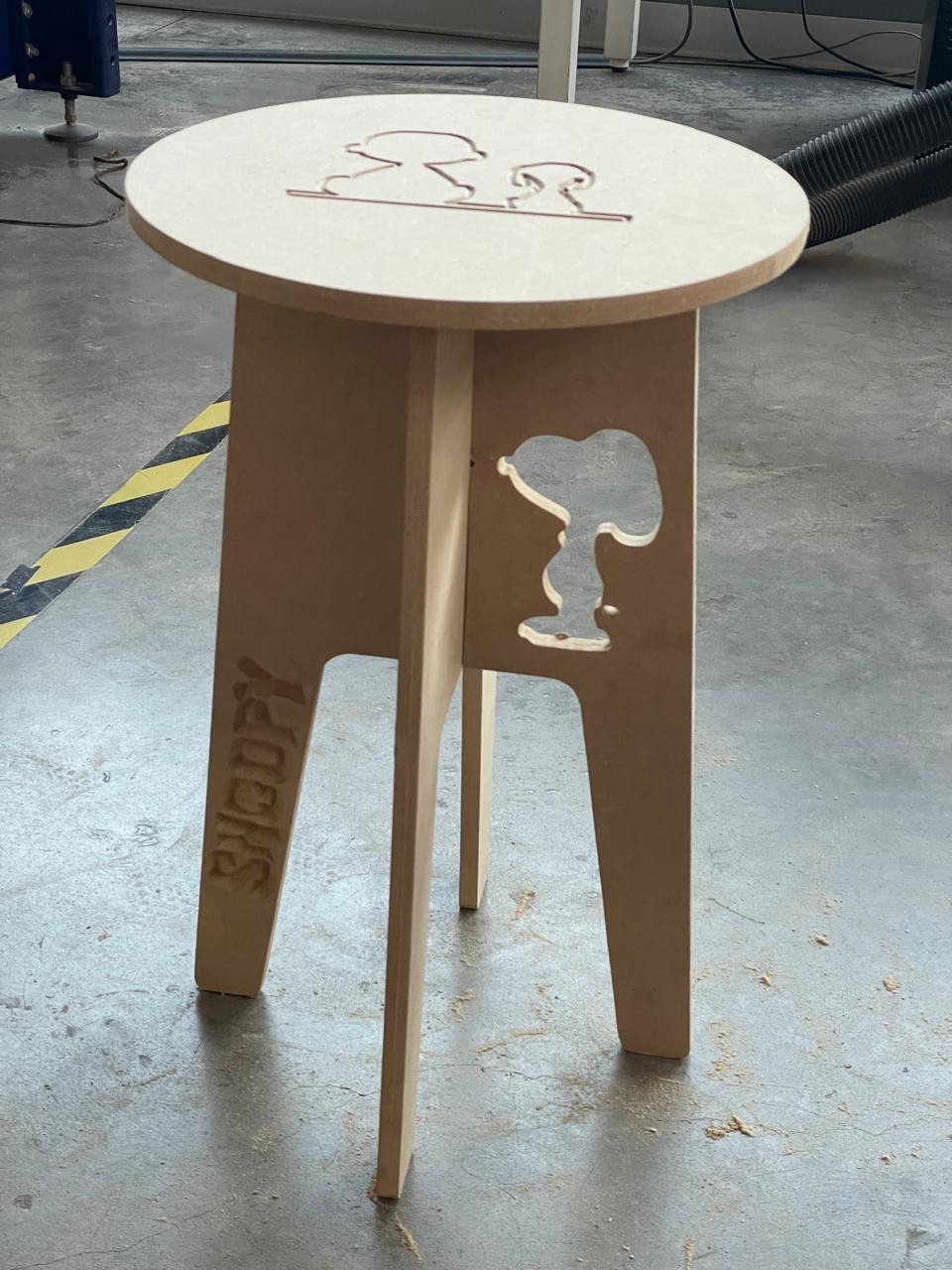
Front view of the finished bench — the Snoopy silhouette cut through the side panel creates a clean decorative window, and the V-carved "SNOOPY" text is visible below it. The interlocking cross-slot joint is visible at the base where the two panels meet.
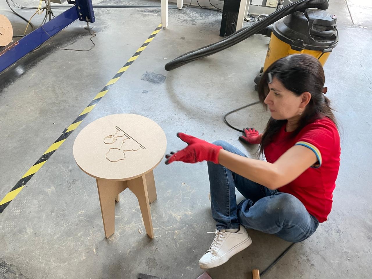
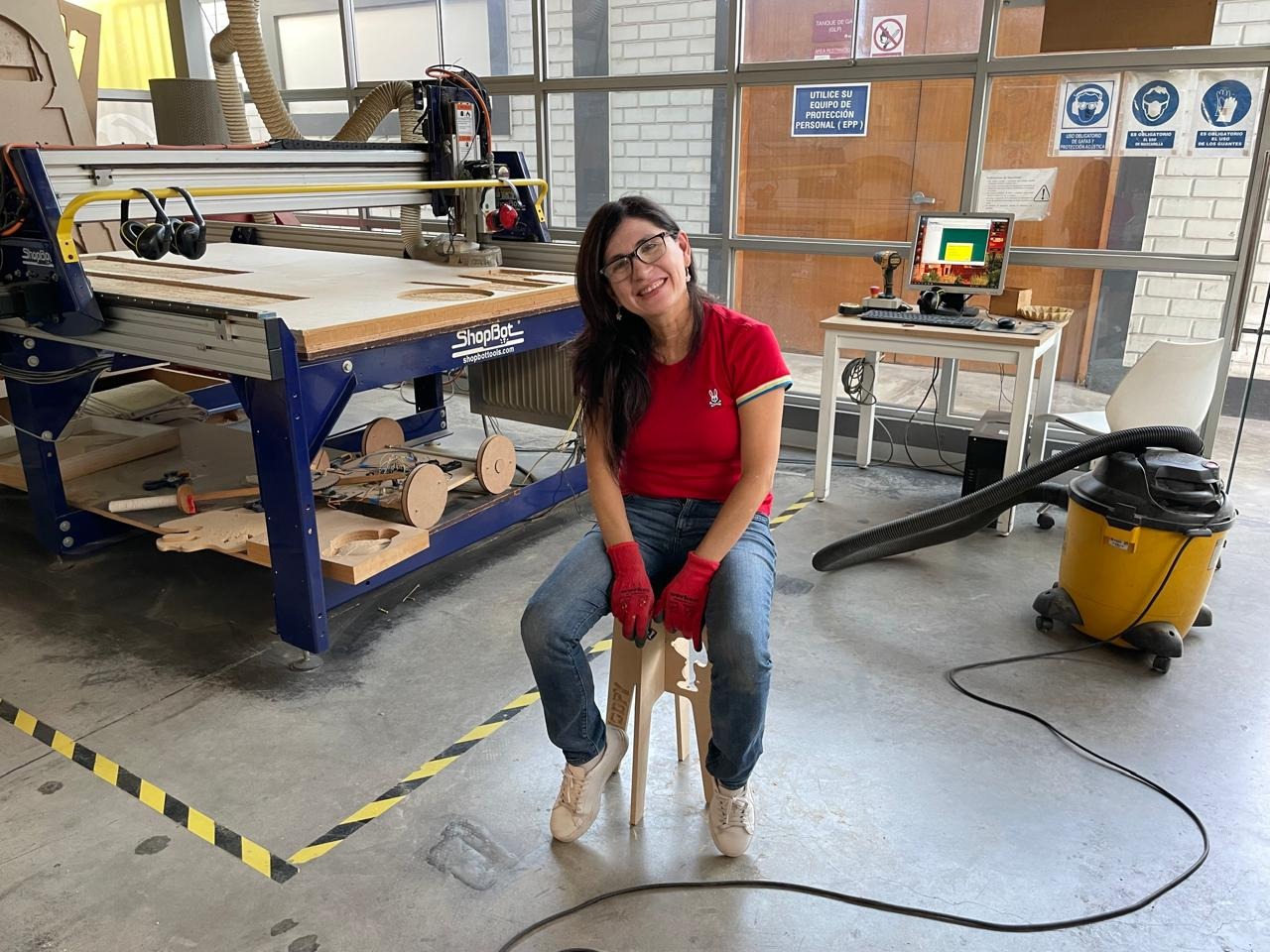
The finished Snoopy bench — and the proof that it holds. The bench passes the structural test: sitting on it at the ESAN Fab Lab with the ShopBot visible in the background. The circular top, the Snoopy silhouette window, and the press-fit joints are all clearly visible.
Problems & Solutions
⚠️ Problem 1 — Snoopy vector too complex for the 1/4" bit
The original Snoopy SVG had very fine detail — thin curves and narrow gaps between shapes — that are too small for a 1/4" (6.35 mm) bit to resolve. The first test cut produced frayed, torn edges and missed several small features entirely.
✅ Solution
I simplified the Snoopy vector in Inkscape, removing paths narrower than approximately 8 mm and merging overlapping curves into a single clean outline. The simplified version cut cleanly with the 1/4" bit. The lesson: always check your minimum feature size against the bit diameter before cutting — a 1/4" bit cannot cut any feature smaller than 6.35 mm, and features near that size will have rough edges.
⚠️ Problem 2 — Slot width too tight on first version
The initial DXF had the cross slot sized at exactly 12 mm — the nominal thickness of the MDF. The actual measured thickness was 11.8 mm, but more importantly, after cutting, the slot kerf (tool path + tool radius) made the slot slightly too narrow for the side panel tabs to slide in without forcing.
✅ Solution
I updated the slot width to 12.2 mm in the revised DXF (Top_v3.dxf), which gave a snug press fit without requiring a mallet. If the fit is too loose, the joint is weak; too tight and you risk cracking the MDF when assembling. A 0.1–0.3 mm tolerance above measured material thickness typically gives a good friction fit.
⚠️ Problem 3 — MDF dust accumulation obscuring the work
MDF produces very fine, light dust that settles across the entire bed and the part surface during cutting, making it difficult to inspect the work between passes and to verify that engravings are cutting at the correct depth.
✅ Solution
I paused between each toolpath and vacuumed the bed and part surface before starting the next operation. This added time but allowed me to confirm that each step was correct before committing to the next. The dust collection skirt on the ShopBot spindle helps significantly but does not capture everything.
Reflections
This was the most physically demanding and logistically complex week of Fab Academy so far. The ShopBot is a large, loud, and powerful machine that demands full attention throughout the job. Unlike the laser cutter, where you can step back and watch through a window, working at the CNC router means standing at the machine, monitoring the cut, and making real-time decisions about whether to continue or stop.
The most important lesson was about the relationship between design and material reality. Nominal dimensions — 12 mm MDF, 1/4" bit — are never exactly what you measure in practice. Every dimension in the design needs to account for kerf, bit radius, material variation, and T-Bone overcuts. A designer who does not understand these tolerances will produce files that look perfect on screen but fail in the machine.
The Snoopy bench also taught me something about personalization and meaning in fabrication. The choice to include the Snoopy character — the same one that appears in my final project (PitchLight) — made the piece feel connected rather than arbitrary. A piece of furniture that tells a story, even a small one, is more valuable than a generic object. That observation applies equally to entrepreneurship: products that carry meaning and identity stand out from products that are merely functional.