
Fab Academy
Review the safety data sheets for each of your molding and casting materials, make and compare test casts with each of them, and compare mold making processes. What I knew beforehand
My experience with baking — cookies, cakes, bread — gave me an intuitive foundation for this week's concepts. A baking mold defines the shape; the batter is the casting material; the oven provides the energy for curing. The analogy is not perfect, but it made the process logic immediately understandable.
I also find it genuinely enjoyable to experiment with different materials and techniques, and to understand the specific properties and applications of each one. The idea of producing multiple identical parts from a single mold — something that would take hours to 3D print individually — seemed both practical and powerful.
This documentation was produced in June 2026. Before this week, my closest reference for mold-and-cast logic came from baking. That analogy proved accurate enough to make the process immediately intuitive. What I had not done before was design a two-part mold from scratch in Fusion 360, machine-print the containers, and produce multiple cast parts from a single silicone master. The choice of a doghouse shape was deliberate: it connected this week's fabrication exercise directly to my final project and gave the silicone mold a functional and recognizable identity from the start.
Molding and Casting — Two-Part Silicone Mold
Individual assignment
Design a mold around the process you'll be using, produce it with a smooth surface finish that does not show the production process toolpath, and use it to cast parts.
Review the safety data sheets for each of your molding and casting materials, make and compare test casts with each of them, and compare mold making processes. What I knew beforehand
My experience with baking — cookies, cakes, bread — gave me an intuitive foundation for this week's concepts. A baking mold defines the shape; the batter is the casting material; the oven provides the energy for curing. The analogy is not perfect, but it made the process logic immediately understandable.
I also find it genuinely enjoyable to experiment with different materials and techniques, and to understand the specific properties and applications of each one. The idea of producing multiple identical parts from a single mold — something that would take hours to 3D print individually — seemed both practical and powerful.
This documentation was produced in June 2026. Before this week, my closest reference for mold-and-cast logic came from baking. That analogy proved accurate enough to make the process immediately intuitive. What I had not done before was design a two-part mold from scratch in Fusion 360, machine-print the containers, and produce multiple cast parts from a single silicone master. The choice of a doghouse shape was deliberate: it connected this week's fabrication exercise directly to my final project and gave the silicone mold a functional and recognizable identity from the start.
Group assignment
Check this link
Individual assignment
Project Context
For this assignment I designed and produced a two-part silicone mold of an iconic doghouse.
The process involved designing the master model and the mold container in Fusion 360, 3D printing both pieces, and then casting silicone (Silicon Perú Silicona F-10 PLUS) around the master to produce a two-part flexible mold. Once the silicone cured, the mold was used to cast parts using a two-part polyurethane resin (Silicon Perú Resina A+B).
Why a two-part mold?
The house shape has undercuts and geometry that makes it impossible to demold from a single-piece mold without destroying either the mold or the cast. A two-part mold with a parting line at the widest cross-section of the shape allows the cast part to be removed cleanly after curing without deformation.
The house shape has undercuts and geometry that makes it impossible to demold from a single-piece mold without destroying either the mold or the cast. A two-part mold with a parting line at the widest cross-section of the shape allows the cast part to be removed cleanly after curing without deformation.
Materials and Tools
Silicon Perú Silicona F-10 PLUS,
Catalyst (blue bottle),
Silicon Perú Resina A+B,
Nitrile gloves,
Digital scale,
Mixing cups,
Wooden stir sticks,
Paper towels,
Kraft paper (workspace cover),
Blue masking tape,
3D-printed mold containers (PLA+, blue),
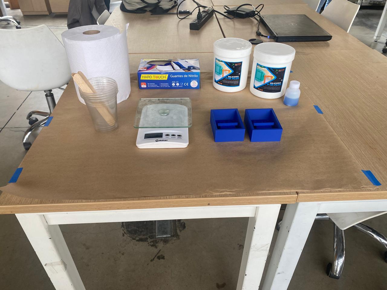
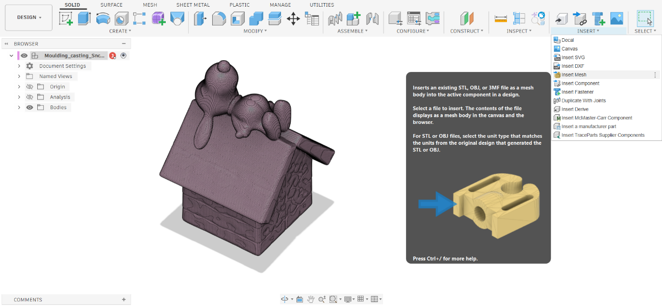
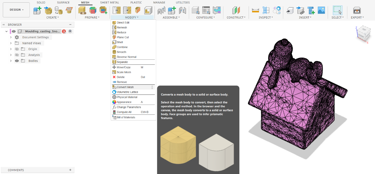
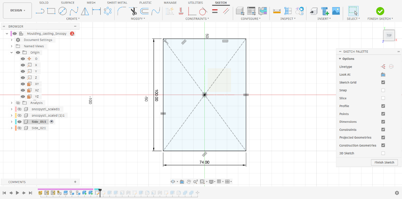
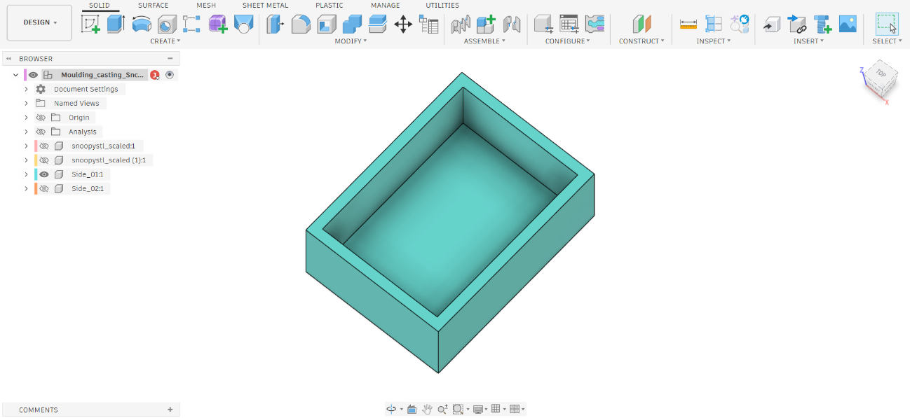
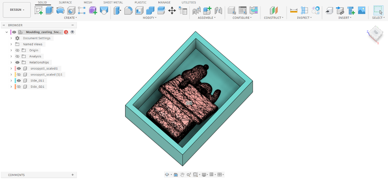
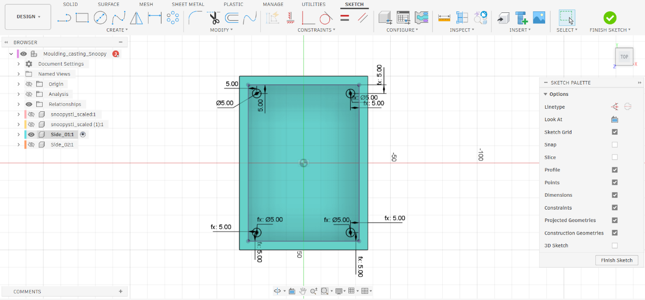
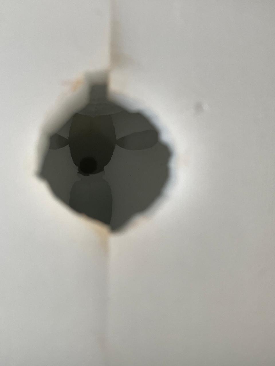
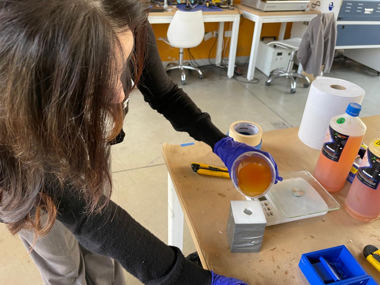
3D-printed master model Before starting, the workspace was prepared carefully. The workbench was covered with kraft paper secured at the corners with blue masking tape, protecting the surface from silicone and resin spills. All materials and tools were laid out in a logical order — scale and mixing cups to the left, mold containers to the right, and the silicone components and catalyst within reach — so that the entire process could flow without interruptions once mixing began. Good workspace preparation is critical in casting work. Both silicone and resin have limited pot life once mixed, and having to search for a tool mid-process can cause the material to become too thick to pour correctly. Workspace ready — kraft paper covers the workbench surface. From left to right: mixing cups with stir sticks, paper towels, nitrile gloves box, two containers of Silicona F-10 PLUS with catalyst bottle, digital scale, and the two blue 3D-printed mold containers.Top-down view of the workspace — the same materials viewed from directly above. The two blue mold containers are positioned to the right of the scale, ready to receive the silicone. The masking tape secures the kraft paper to the table edges. The mold system was designed in Fusion 360 around a Snoopy-in-his-doghouse model downloaded as an STL from MakerWorld (makerworld.com/en/models/1835322-snoopy). The design process produced two matching mold matrix halves — 1Import the mesh The STL file was imported into Fusion 360 using Insert → Insert Mesh. Fusion 360 accepts STL geometry directly as a mesh body, making it straightforward to work with models sourced from repositories like MakerWorld without rebuilding the geometry from scratch. The Snoopy-on-doghouse model appears in the canvas with visible triangle facets. Step 1 — The STL file imported into Fusion 360 via Insert → Insert Mesh. The Snoopy model appears as a mesh body in the canvas. The tooltip on the right describes the Insert Mesh operation and explains how the file is inserted as a mesh body into the active component. 2Convert the mesh to a solid The mesh was converted to a solid body using Mesh → Modify → Convert Mesh. This step is required to enable all subsequent boolean and sketch operations — Fusion 360's solid design tools do not operate on mesh triangles. After conversion, the Snoopy body appears in the browser as a solid (BRep), and the MESH tab is replaced by the SOLID workflow. Step 2 — The Convert Mesh dialog in Fusion 360 (MESH tab active). The model is highlighted in pink to indicate it is still a mesh body. The tooltip explains that the mesh converts to a solid or surface body using face groups to infer prismatic features. 3Cut the solid in half using the XZ plane The converted solid was split into two halves using Modify → Split Body, with the XZ plane as the cutting tool. This defines the parting line — the plane where the two mold halves will meet. The XZ plane passes through the widest cross-section of the Snoopy figure so each half can demold cleanly without undercut interference. After the split, two solid bodies appear in the browser: Step 3 — The Split Body command selected from the Modify menu. The two resulting halves are visible in contrasting colors (pink upper / blue lower), showing the parting plane at the widest cross-section of the figure. The browser tree confirms the two resulting solid bodies. 4Create a rectangle sketch A new sketch was created on the parting plane (XZ) and a rectangle was drawn around the half-model. The dimensions — 74 mm wide × 100 mm tall — were set to provide sufficient wall clearance on all sides of the Snoopy figure. This rectangle defines the outer footprint of the mold container box that will hold the silicone. Step 4 — The rectangle sketch viewed from the top (TOP orientation cube visible top-right). Dimensions of 74.00 mm wide and 100.00 mm tall define the mold box footprint. The diagonal construction lines trace the existing model bodies beneath the sketch plane. 5Create the mold box (Extrude + Shell) The rectangle profile was extruded 37 mm in height to form a solid block. A Shell operation with a 5 mm wall thickness was then applied, hollowing the block from the open top face and leaving uniform 5 mm walls on all sides and the base. The result is a sturdy open-top container — the mold matrix — that holds the master model in position and contains the silicone during the pour. Step 5 — The finished mold container after Extrude (37 mm) and Shell (5 mm walls). The teal open-top box is shown in isometric view. The component browser on the left shows the four components: the two Snoopy halves (Side_01 and Side_02) alongside the mold box body. 6Convert to components and combine the pieces Both solids — the mold box and the embedded Snoopy half — were converted to Fusion 360 components and brought together as a single assembly. This ensures the half-model is correctly positioned inside its container, and that subsequent operations (sketches for the registration pins) reference the correct geometry. Step 6 — The Snoopy half-model (pink mesh) combined with the teal mold container as a single assembly. The model sits flush with the parting face of the box. The Relationships node in the component tree confirms the assembly structure. 7Sketch the registration pin positions A new sketch was created on the interior base face of the mold container. Four circles of Ø 5 mm were placed at the corners, offset 5 mm from each wall edge. These circles define the footprints of the alignment cylinders that will ensure the two mold halves register precisely when assembled — any lateral offset between the halves during a resin pour would produce a misaligned cast part. Step 7 — The registration pin sketch viewed from the top. Four Ø 5.00 mm circles are positioned at the corners of the mold box interior, each offset 5 mm from the adjacent walls. All dimensions are shown as driven parameters (fx: 5.00 and fx: Ø5.00). 8Extrude the registration pins The four circles were extruded upward as solid cylinders. These pins press into the soft silicone of the opposite mold half when the two halves are first assembled, creating matching holes. When the mold is reassembled for casting, the pins and holes interlock and prevent any lateral shift between the two silicone halves during the resin pour. Step 8 — The mold container after extruding the four registration pins. The small cylinders are visible at each corner of the teal box interior. The Snoopy half-model mesh sits centrally inside. The Relationships node in the browser confirms the updated assembly structure. Steps 4–8 were repeated symmetrically for the second Snoopy half, producing the complementary mold container (Side_02, shown in yellow/gold) with matching registration features. Both completed mold matrix halves are shown here side by side. Each was then exported as an STL file — Step 9 — Both mold matrix halves completed and shown together in Fusion 360: Side_01 (teal, left) and Side_02 (yellow, right). Each container holds its corresponding Snoopy half-mesh. The registration pin positions on Side_01 match the receiving holes on Side_02. Both were exported as STL files for printing. 103D print the mold containers Both STL files were sliced in Bambu Studio and printed simultaneously on the same plate on the Bambu Lab X1 Carbon. The Slicing Result panel confirms all print statistics: Step 10 — Both mold matrix halves sliced in Bambu Studio for the X1 Carbon. The Slicing Result panel confirms: 0.20 mm layer height, PLA Basic, total filament 131.67 g, total print time 3 h 30 min. No supports were needed for either half. The parting line — the plane where the two mold halves meet — was placed at the widest cross-section of the Snoopy figure using the XZ plane. This ensures both halves demold cleanly without the container walls interfering with any undercut geometry on the figure. The two 3D-printed blue PLA+ mold containers after printing — photographed open from above. The interior geometry is visible: each half contains the Snoopy model's impression along one face, plus the registration pin features at the corners. The two containers form a matching pair that, when stacked, create the complete mold cavity ready to receive the silicone pour. 1Assemble and secure the mold containers The master model was placed inside one half of the mold container, positioned precisely so the parting line would fall at the widest cross-section of the house. The registration pins on the container halves were used to align the two halves correctly. The assembled container was placed on the kraft-paper-covered workbench, ready to receive the silicone pour. No release agent was required between the silicone and the 3D-printed PLA+ container, since silicone does not bond permanently to PLA. However, a thin coat of petroleum jelly was applied to the master model surface to ensure clean demolding after the silicone cured. 2Measure the silicone and catalyst by weight The Silicon Perú Silicona F-10 PLUS uses a base + catalyst system: the white silicone paste is the base, and the blue liquid is the catalyst that triggers the curing reaction. The mixing ratio by weight is specified in the product datasheet — the catalyst was added at the percentage indicated and the combined mixture was placed on the digital scale to confirm the correct total weight before mixing. Measuring by weight rather than by volume is more accurate for silicone systems, since the base and catalyst have different densities. An incorrect ratio produces silicone that either does not cure fully (too little catalyst) or cures with a compromised surface quality (too much catalyst). 3Mix the silicone The catalyst was added to the silicone base in the mixing cup and stirred slowly and thoroughly for the time specified in the datasheet — typically 3–5 minutes for this product. Mixing was done with a wooden stir stick in a circular motion, regularly scraping the sides and bottom of the cup to incorporate all the material evenly. Slow, deliberate mixing is critical. Aggressive or rapid stirring introduces air into the silicone, which produces bubbles in the finished mold surface. Any bubble that appears on the face of the mold that contacts the master will be transferred as a raised bump to every cast part produced from that mold. 4Pour the silicone The mixed silicone was poured in a thin, continuous stream from a height of approximately 20–30 cm above the mold opening. Pouring from a height helps break any surface bubbles as the stream falls. The pour was directed to one corner of the mold first, allowing the silicone to flow naturally toward the master model and push any air ahead of it toward the vents. Once the first half was filled, the process was repeated for the second half of the mold container. Both halves were then left on a flat, vibration-free surface to cure overnight. 5Cure and demold The silicone was left to cure overnight at room temperature. After curing, the mold container halves were separated by removing the registration pins and gently pulling the two blue PLA+ halves apart. The flexible silicone block was then carefully peeled away from the master model — silicone's flexibility makes this process straightforward even for shapes with moderate undercuts. The result was two matching flexible silicone mold halves with the negative impression of the doghouse enclosure captured cleanly on the interior face of each half. Side-by-side comparison — left column: the cured white silicone mold halves showing the negative impression of the doghouse; right column: the original blue PLA+ 3D-printed containers showing the master model still inside. The top row and bottom row show the two complementary halves of each mold system. Once the silicone molds were cured and demolded, they were used to cast parts using Silicon Perú Resina A+B — a two-part polyurethane resin. The two silicone mold halves were reassembled, aligned using the original registration pins from the 3D-printed containers, and secured together with rubber bands before pouring. View into the mold cavity from above — the negative impression of the doghouse enclosure is clearly visible inside the mold. This is what the cast resin will fill when poured in, producing a part that matches the original master geometry. Mixing and pouring the two-part material on the digital scale at the ESAN Fab Lab workstation. Nitrile gloves are worn throughout the process. The Silicon Perú Resina bottles (components A and B) are visible in the background alongside the workspace materials. The resin was left to cure for the time specified in the product datasheet. After curing, the rubber bands and registration assembly were removed, the two silicone mold halves were gently separated, and the cast part was removed. The flexibility of the silicone made demolding straightforward even in the areas where the house geometry created narrow channels. The two-part silicone mold successfully captured the geometry of the doghouse enclosure master. The cast part produced from the resin reproduced the overall house shape cleanly, including the angled roof profile and the rectangular base. The mold was reused multiple times without significant degradation of surface quality. Final result — the white two-part silicone mold open (left) alongside the cured resin cast of the doghouse (right). The cast part is an ivory/cream color and retains the house shape including the roof angle and the decorative bee figure that is part of the enclosure design. The mold interior shows the clean negative impression that produced the cast.
Material Description Role in process
Silicona F-10 PLUS (A+B)
Silicon Perú two-part silicone, white paste
Mold material — fills around the master to create the flexible mold
Catalyst
Blue liquid activator for the silicone
Triggers curing of the silicone when added to the base
Resina A + Resina B
Silicon Perú two-part polyurethane resin, amber liquid
Casting material — poured into the finished silicone mold to produce the final part
3D-printed mold containers
PLA+ blue, printed on Bambu Lab
Hold the master model in position and define the outer walls of the silicone block
Digital scale
Miray precision scale
Measuring silicone base and catalyst by weight for accurate ratio
Workspace Setup
Mold Design
Snoopy_sideA and Snoopy_sideB — which were then 3D printed and used as the containers for the silicone pour. The ten steps below document the full design workflow.Step-by-Step: Mold Matrix Design in Fusion 360
snoopystl_scaled and snoopystl_scaled (1).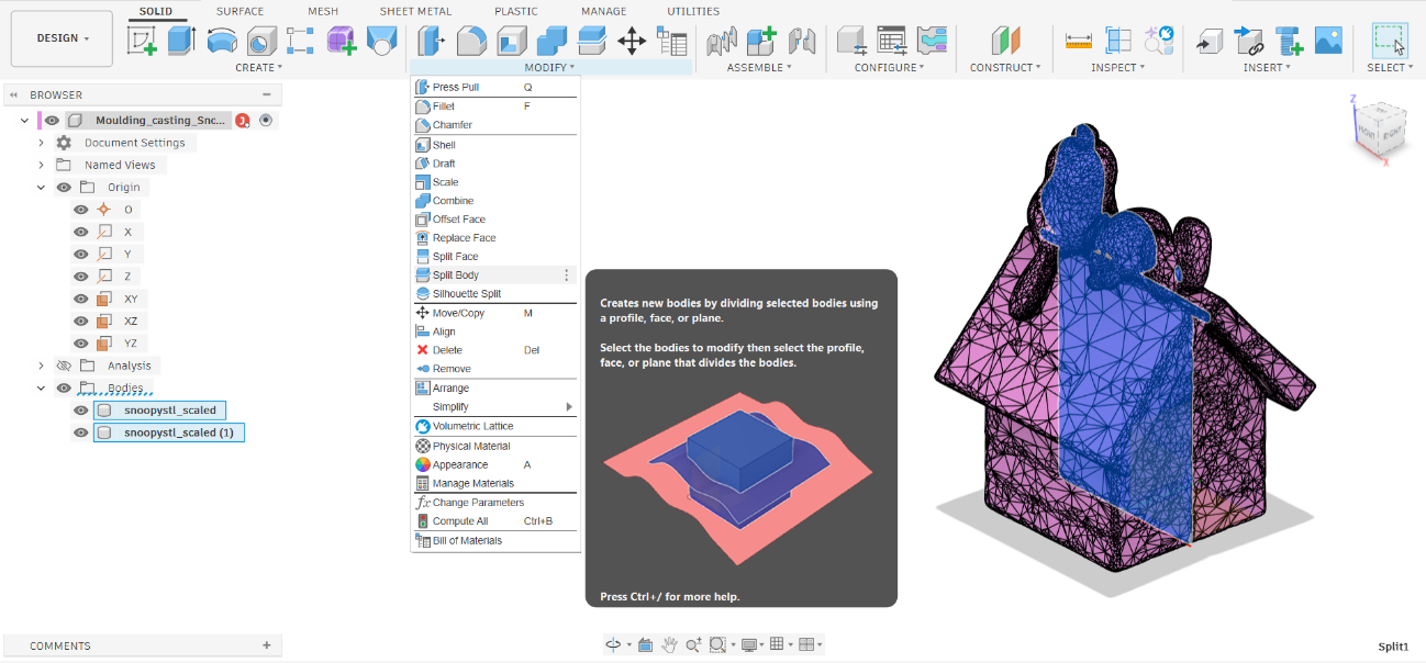
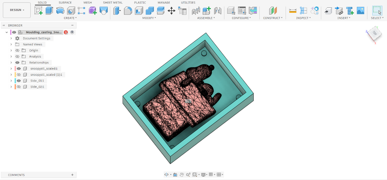 9Repeat the process for the second half and export as STL
Snoopy_sideA.stl and Snoopy_sideB.stl — ready for 3D printing.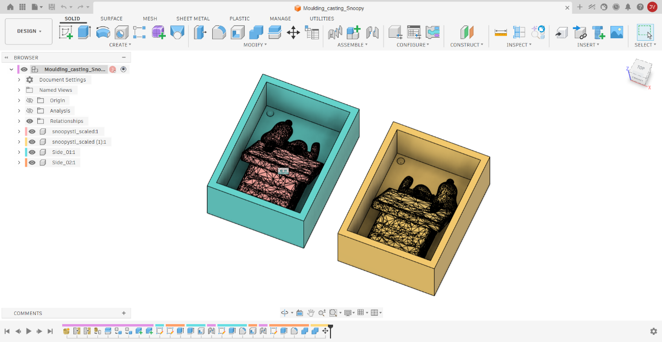
Printer Bambu Lab X1 Carbon Material PLA Basic Layer height 0.20 mm Standard @BBL X1C Walls 2 Sparse infill density 15% Supports No Total print time 3 h 30 min Total filament 131.67 g 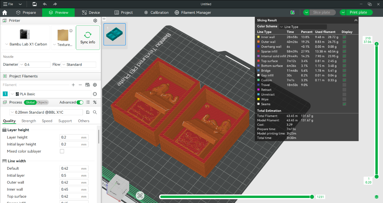
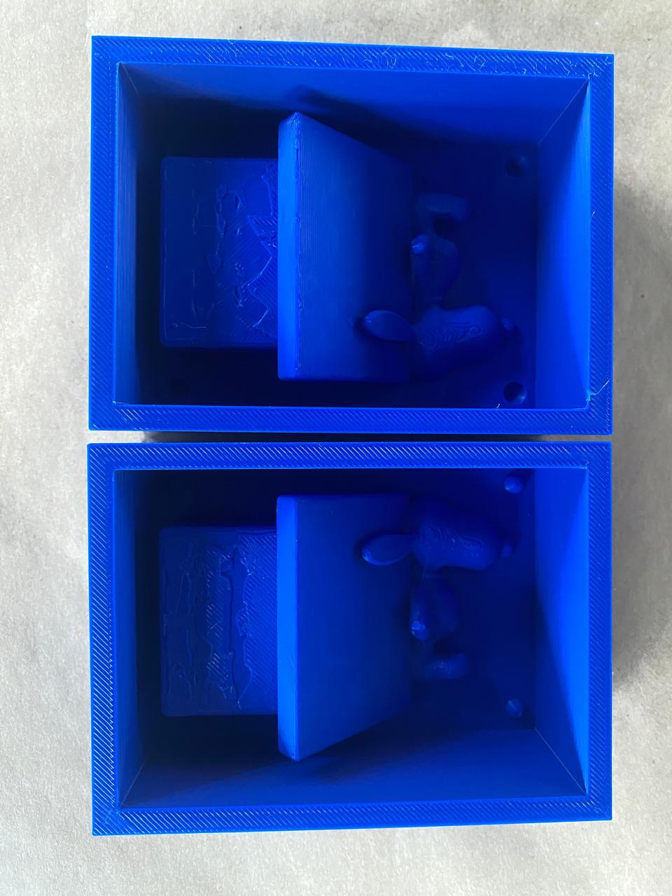
Silicone Molding Process
Materials
Silicon Perú Silicona F-10 PLUS (base + catalyst) for the mold · Silicon Perú Resina A+B for casting · 3D-printed containers in blue PLA+ on Bambu Lab X1 Carbon · Print time: 3 h 30 min · Filament: 131.67 g.
Comparison: Silicone Molds vs. 3D-Printed Containers
Part of this assignment involved comparing the two mold systems side by side — the finished white silicone molds and the original blue 3D-printed containers that were used to cast them.
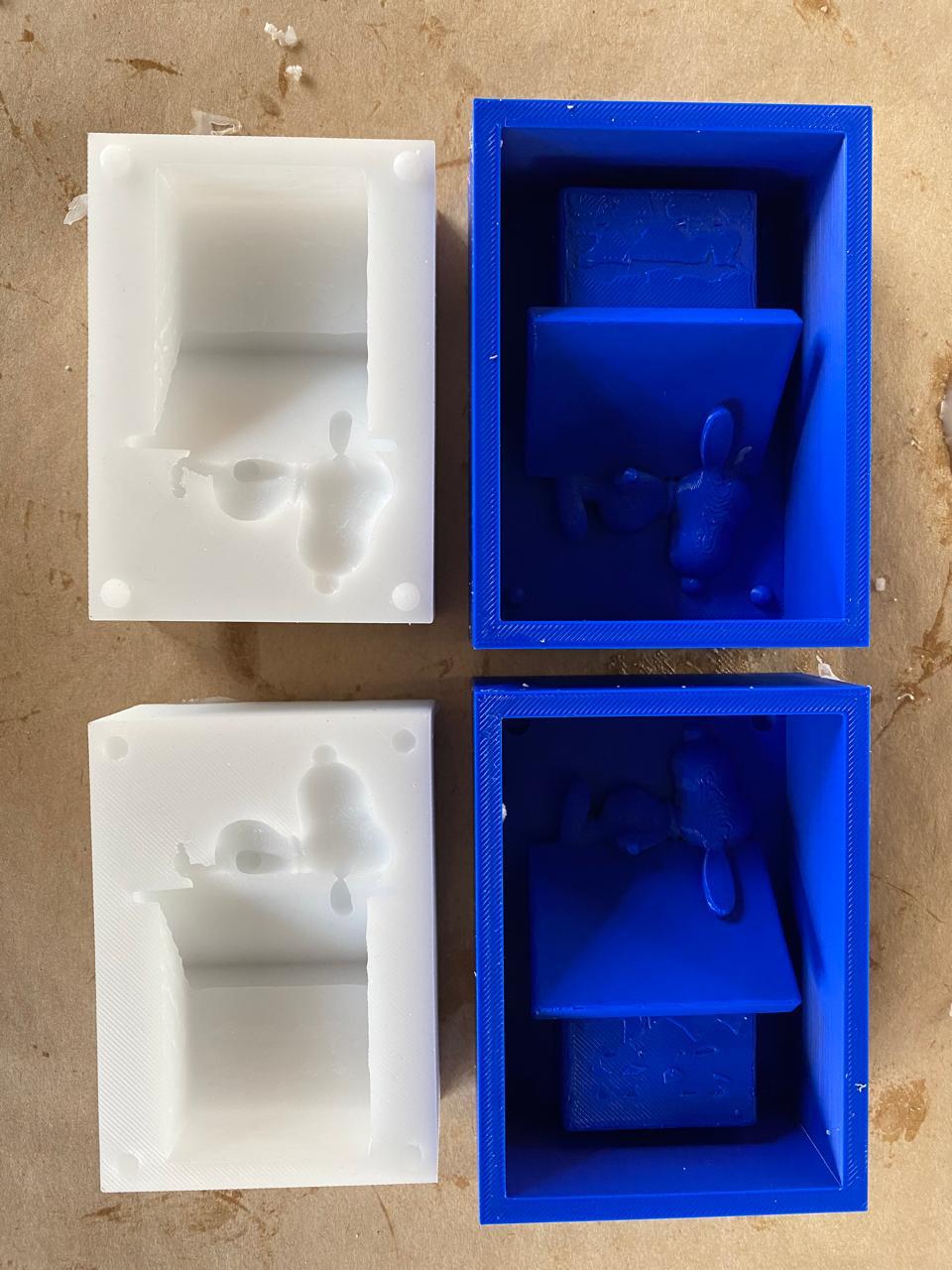
Feature 3D-Printed Container (blue PLA+) Silicone Mold (F-10 PLUS)
Material
Rigid PLA+ plastic
Flexible silicone rubber
Role
Holds master in position during silicone pour
Final mold used to cast the parts
Surface detail
Shows 3D printing layer lines on interior
Captures exact surface detail of master; no layer lines
Demolding
Rigid — master removed after silicone cures
Flexible — stretches over undercuts for clean release
Reusability
Reusable for multiple pours of the same geometry
Dozens of casts possible before surface degrades
Casting with Two-Part Resin
Result
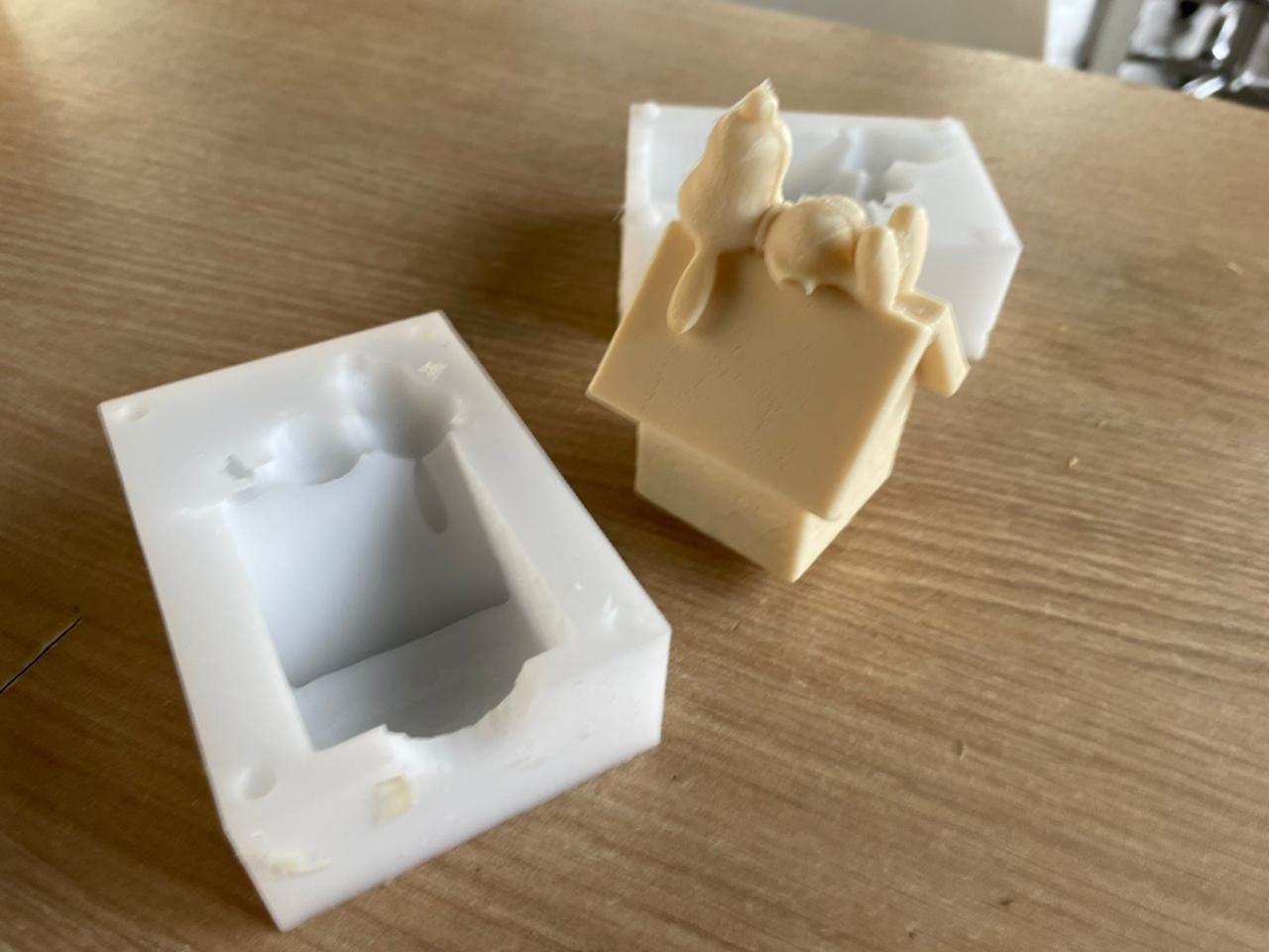
Problems & Solutions
⚠️ Problem 1 — Layer lines transferred to the silicone mold surface
The master model was 3D printed, and even at 0.1 mm layer height, faint layer lines were visible on the surfaces that contacted the silicone. These lines were captured by the silicone and transferred to the cast parts, appearing as fine horizontal ridges on the flat faces of the enclosure.
✅ Solution
The master surfaces were lightly sanded with 400-grit sandpaper and then 800-grit before the first pour. This reduced the layer line texture significantly. For future iterations, sanding up to 1200-grit and applying a thin coat of primer to the master before casting would eliminate the lines entirely.
⚠️ Problem 2 — Air bubbles trapped in the silicone near fine detail areas
The decorative bee figure on the enclosure has thin protruding geometry. Air became trapped in these narrow areas during the silicone pour, leaving small voids on the mold surface in those locations.
✅ Solution
The silicone was first brushed carefully over the master's detailed surfaces with a small brush before pouring the bulk of the material. This technique — called "painting" the mold — ensures the first layer of silicone contacts all fine detail and displaces any trapped air before the main pour fills the rest of the cavity.
⚠️ Problem 3 — Resin leaked at the parting line during casting
On the first pour with the silicone mold, a small amount of resin leaked through the parting line where the two silicone halves met. This produced a thin flash on the cast part at the parting line that needed to be trimmed.
✅ Solution
The two mold halves were clamped more firmly together using additional rubber bands and a strip of masking tape along the parting line edge. The flash on the cast part was trimmed with a hobby knife. For future mold designs, adding a small compression lip to the parting line geometry would eliminate this issue without requiring external clamping.
Safety Considerations
⚠️ Safety — Silicone and Polyurethane Resin
Reflections
It is remarkable what can be achieved in terms of customization and experimentation with mold-based production. The ability to design a shape once, cast it in silicone, and then reproduce it repeatedly in different materials — resin, wax, plaster — opens a range of possibilities that go well beyond what 3D printing alone can offer.
This prototyping technique serves as a bridge between digital design and analog product manufacturing at a larger scale. It is particularly relevant for entrepreneurship contexts: a well-designed mold can enable a small producer to offer a consistently high-quality product without the per-unit cost and time of additive fabrication.
The practical lessons were equally valuable: the importance of a smooth master surface (since every texture is captured and transferred to every cast), the need to measure components by weight rather than volume for consistent results, and the critical role of preparation before the material is mixed and the pot life begins.
Resources
Download the files used in this assignment
The files below are the STL exports of the two mold matrix halves, ready to 3D print. The master model (Snoopy in his doghouse) was sourced from MakerWorld and the mold containers were designed around it in Fusion 360 as described above.
Licensed under CC BY-NC-SA 4.0