Mechanical Design — Design a machine that includes mechanism + actuation + automation + function + user interface. Build the mechanical parts and operate it manually. Document the group project and your individual contribution.
Week 12B
Machine Design — Actuate and automate your machine. Document the group project and your individual contribution. Prepare a demonstration.
Group assignment
My background is in economics and entrepreneurship education — not in engineering or manufacturing. Before this week, I had never designed a machine, worked with stepper motors, or thought about how mechanical motion systems are built. My closest reference point was observing the machines we had used in previous Fab Academy weeks, without having looked at what was happening inside them.
What I did bring to this project was the ability to research quickly, think systematically about how components relate to each other, and stay persistent when things did not work as expected. Those turned out to be genuinely useful skills in a process that involved a lot of trial and error.
This week's work was carried out in 2025, as part of a collaborative machine design project at ESAN Fab Lab. My contribution was as an economist and educator participating in research, assembly coordination, and software testing — not as the lead engineer of the mechanical or electronic systems. The team experience was valuable precisely because it placed me in a role I recognized from my professional life: understanding a technical system well enough to participate meaningfully and document it accurately, without overstating individual contribution. That discipline matters as much in Fab Academy as it does in an entrepreneurship incubator.
Project Overview
Together with my partner Jhasmin Ayala, I built a two-axis pen plotter — the XY (almost) Z Plotter. The machine moves a pen across a drawing surface using three NEMA17 stepper motors on the X and Y axes, with a servo motor controlling the pen lift (Z axis). The control system is an Arduino Uno with a CNC shield running GRBL firmware, operated from a PC through GRBL-Plotter software.
The name reflects the honest state of the project at the end of the week: the X and Y axes worked correctly and the machine could draw; full automatic Z-axis integration remained a pending improvement.
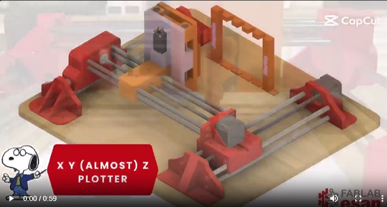
3D render of the XY (almost) Z Plotter design — produced in Fusion 360. The red 3D-printed parts, the steel guide rods, the MDF base, and the Z-axis carriage are all visible. This is the machine we built from scratch during Week 12.
Why an XY plotter?
We chose a plotter because it makes the motion directly visible: you can evaluate accuracy by looking at what the machine draws. It also covers all the required elements — a mechanism (leadscrew linear motion), actuation (stepper and servo motors), automation (GRBL firmware interpreting G-code), and a clear functional output. For a first machine, that combination of simplicity and completeness made it the right choice.
My Individual Contribution
My contribution focused on three areas: research and design reference, physical assembly, and software testing and calibration. I also contributed to documentation throughout the process. Being an economist building a machine for the first time meant learning everything from scratch — but also approaching each problem without preconceptions about how it "should" be done.
1. Research and Design Reference
Before any design work began, I spent time researching existing XY plotter projects to understand the range of possible approaches — different motion systems, frame materials, motor configurations, and software stacks. This research phase was essential for making informed decisions about which components to use given the materials and budget we had available at the Fab Lab.
I looked at projects documented by previous Fab Academy students, open-source plotter repositories, and community builds. From that survey I identified the key design patterns that would work for us: leadscrew-driven axes (rather than belt-driven, which would require different tensioning hardware), 8 mm steel rods with linear bearings as guides, and GRBL as the firmware since it is well-documented and widely used.
This reference work informed the design decisions that Jhasmin then executed in Fusion 360 — selecting the right rod spacing, motor mount geometry, and carriage dimensions. Knowing what had worked for others, and what the common failure points were, helped us avoid several mistakes before fabrication.
2. Assembly
Once the parts were printed and the MDF base was cut, I was actively involved in the physical assembly of the machine. This was new territory for me — I had never assembled a motion system before — and it required paying close attention to details that I had not previously thought about.
1Preparing and organizing components
Before starting the assembly, we laid out all the parts — the 12 3D-printed components, the steel rods, linear bearings, NEMA17 motors, screws, and nuts — and checked that everything matched the design. Having all components organized and accounted for before starting was important because once the assembly begins, stopping to search for a missing part disrupts the process.
2Assembling the linear motion system
Fitting the steel rods into the 3D-printed mounts and threading the linear bearings onto them was physically demanding work that required two people — one to hold the structure in position while the other fastened the screws. I held, aligned, and fastened parts throughout this phase, and used a tape measure to verify that the rod spacing matched the design dimensions before tightening anything permanently.
3Checking alignment by feel and by measurement
After the rods were mounted, we tested the motion by sliding the carriage by hand across the full travel range. If the carriage moved freely with no resistance, the rods were parallel. If it stuck or felt stiff at any point, the rods were slightly out of alignment and the clamps needed to be loosened and adjusted. I repeated this test several times, adjusting the rod positions iteratively, until the motion felt smooth in both axes.
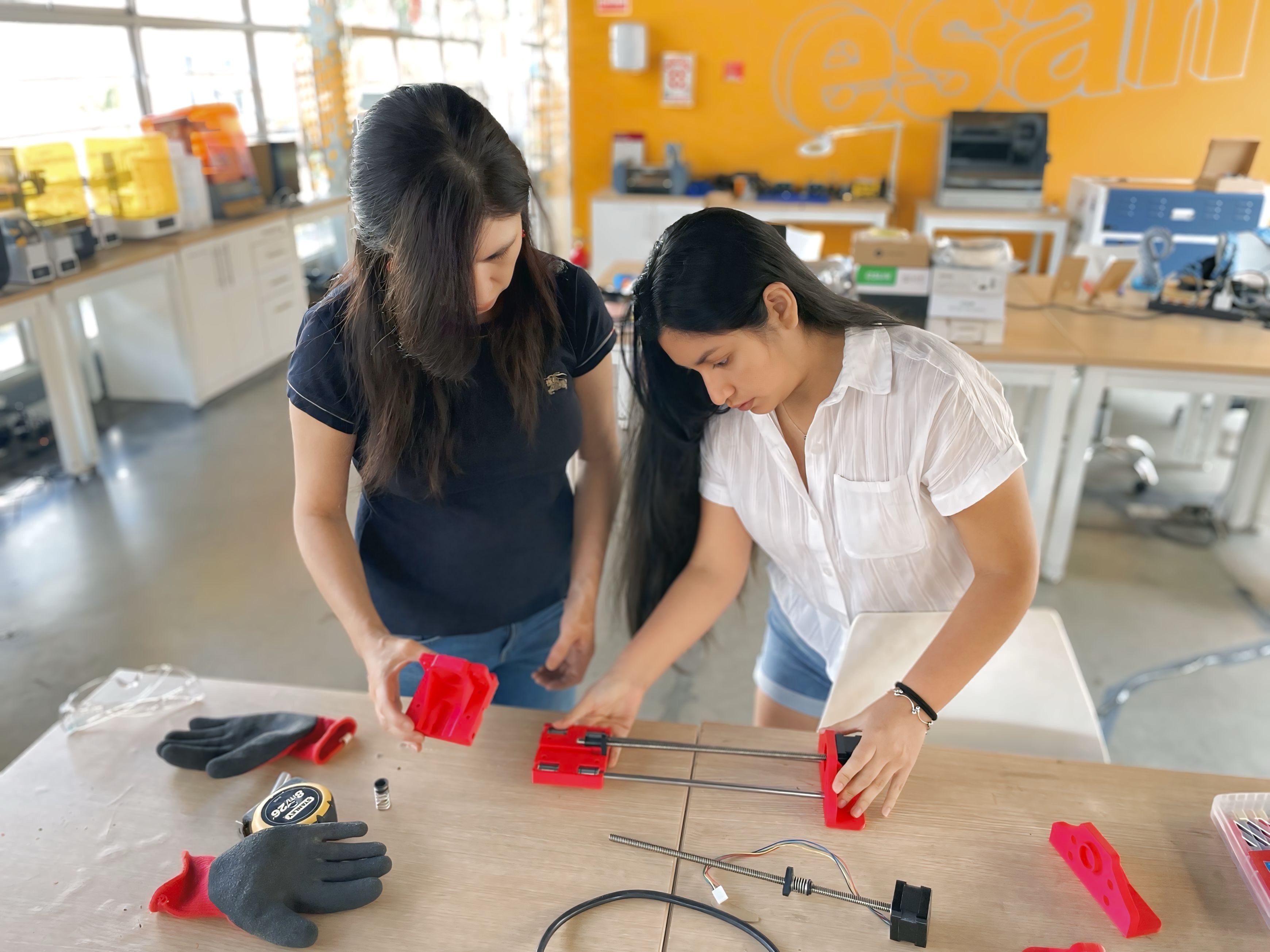
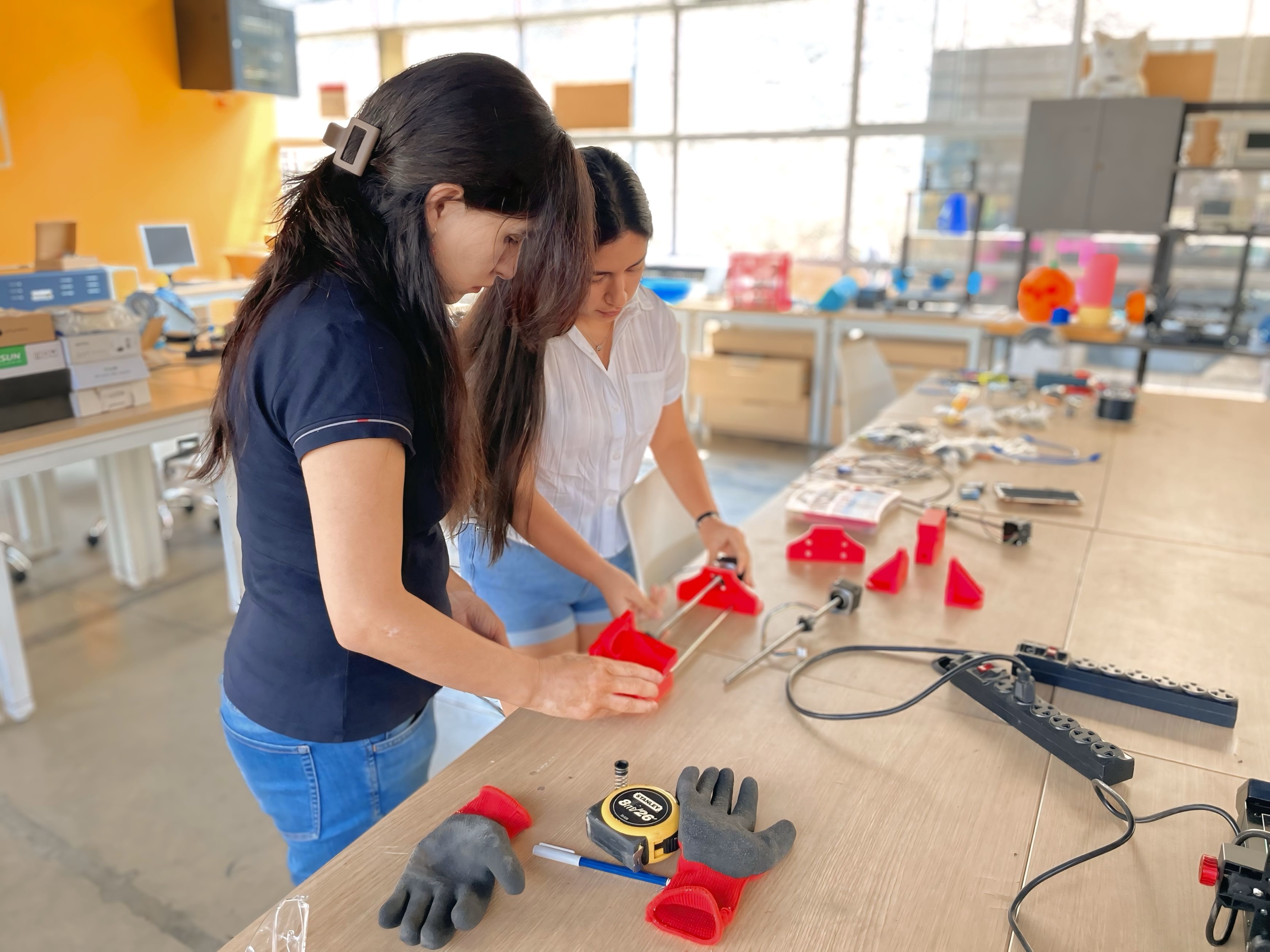
Assembly at the ESAN Fab Lab — working with the red 3D-printed parts and the steel guide rods. The printed mounts, bearings, and axis components are spread across the worktable. This is the early stage of assembling the X-axis linear motion system.
Top-down view of the axis assembly — the steel guide rods are mounted in the red 3D-printed clamps, with the leadscrew motors beginning to take their positions. The ESAN Fab Lab wall is visible in the background. At this stage we were verifying rod spacing and parallelism before fully tightening the mounts.
3. Software Testing and Calibration Support
Once the machine was physically assembled, the next step was making it move correctly through software. This involved installing GRBL firmware on the Arduino, connecting the machine to the GRBL-Plotter software on a PC, and then configuring the motion parameters so that a commanded distance in software produced the correct physical travel on the machine.
The main challenge was that we had no datasheets for our stepper motors, so the standard steps/mm values could not be calculated directly. The solution was to determine them experimentally: command the machine to move a known distance, measure the actual travel, calculate the correction factor, and update the GRBL parameter. I participated in this testing loop — running movement commands, measuring with a tape measure, and recording the results — until the X and Y axes moved accurately.
I also helped test the Z-axis servo behavior and tried different configurations in GRBL-Plotter to get the pen lift to work automatically during a plotting job. We were able to confirm the servo responded correctly when commanded directly, but full automatic integration with the plotting software remained unresolved — which is reflected in the machine's name.
The Machine in Operation
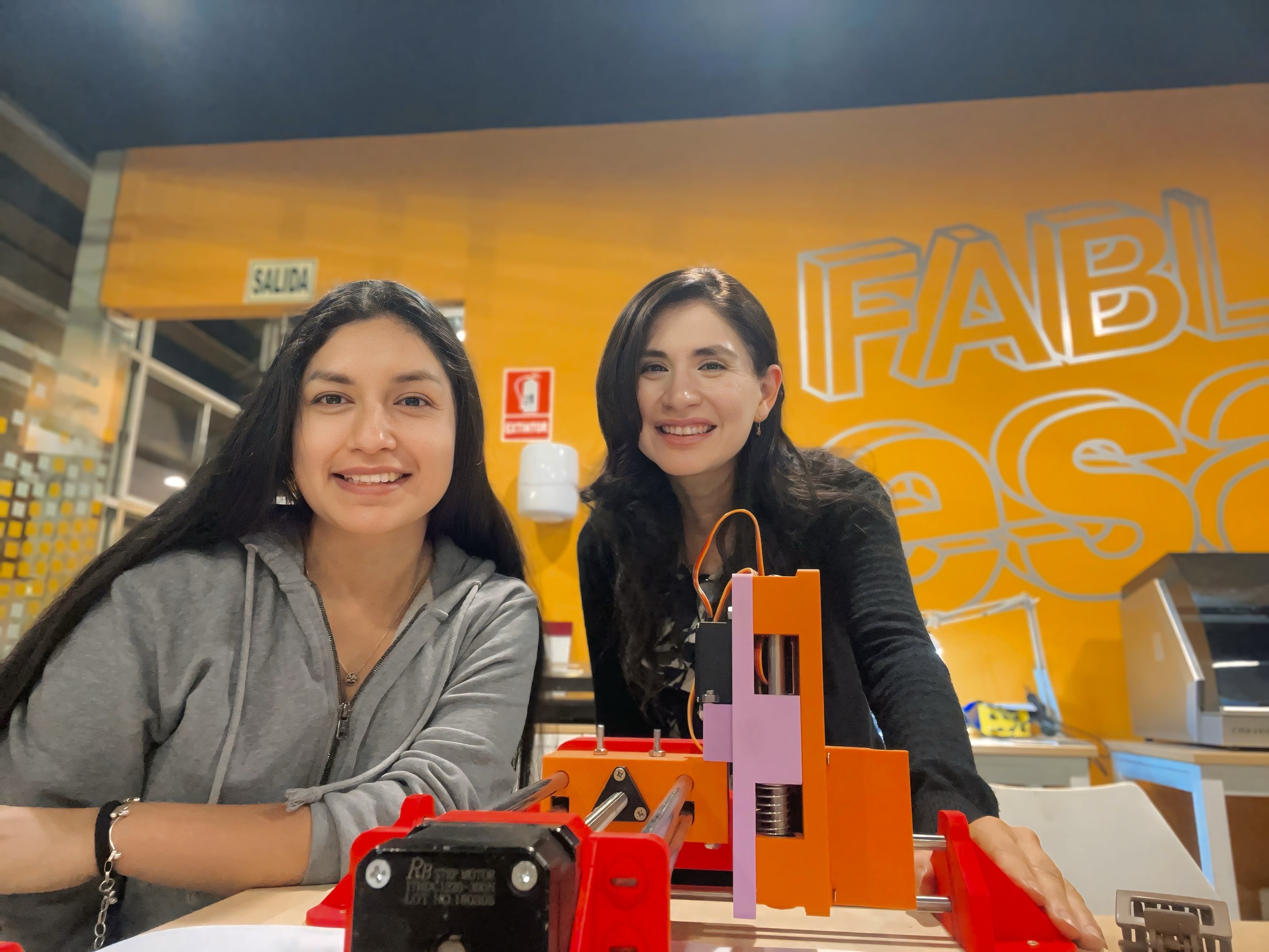
After assembly and calibration, the plotter was able to execute G-code and draw on both X and Y axes with reliable, repeatable motion. The photo below shows Jhasmin and me with the finished machine at the Fab Lab.
With the finished XY (almost) Z Plotter at the ESAN Fab Lab. The orange and red 3D-printed frame, the steel guide rods, the leadscrew motors, and the Z-axis carriage are all visible. The machine was functional on the X and Y axes at this point and ready for its first drawing test.
Problems & Solutions
⚠️ Problem 1 — Understanding what each component does
Coming from a non-technical background, I frequently encountered parts and concepts I did not recognize — linear bearings, leadscrews, stepper driver current settings, G-code parameters. Not knowing what something was made it difficult to contribute meaningfully to decisions about it.
✅ Solution
I made a habit of looking up every unfamiliar term immediately, using the Fab Academy class notes, the GRBL documentation, and the project references I had found during the research phase. Understanding the purpose of each component — even at a basic level — made me a more useful assembly partner and helped me ask better questions during the process.
⚠️ Problem 2 — Carriage binding during assembly
After mounting the rods, the Y-axis carriage moved freely near the center of travel but felt stiff near the ends. We did not initially understand why — to me it looked like the rods were straight.
✅ Solution
After some research we identified the problem: the two rods were not perfectly parallel, so the linear bearings were being forced slightly sideways near the ends of travel. Loosening the rod clamps, adjusting the rod positions by small amounts, and retesting repeatedly resolved it. The lesson was that "straight" and "parallel" are not the same thing, and that motion testing is the only reliable way to verify alignment.
⚠️ Problem 3 — Z-axis not integrating with GRBL-Plotter
The software version we used supports servo-based Z-axis control, but we could not find the right configuration to make it trigger automatically during a plotting job. We tried different parameter settings without success.
✅ Solution (partial)
We confirmed that the servo responded correctly when sent direct commands, and manually adapted some G-code instructions for the Z axis. Full automatic integration remains a pending improvement — hence the "almost Z" in the machine's name. This was an honest acknowledgment that the project was not complete, rather than claiming functionality we had not achieved.
Reflections
This was my first time building a machine of any kind, and the experience was genuinely different from everything else in Fab Academy. Individual processes — cutting, printing, soldering — have clear steps and predictable outcomes. Building a machine means dealing with a system where every component affects every other one, and where problems rarely have a single obvious cause.
What surprised me most was how much of the work was about observation and adjustment rather than following a fixed procedure. Testing the carriage by sliding it by hand, listening for unusual sounds from the motors, watching whether the drawn lines were straight — these were the actual diagnostic tools. Technical knowledge helps, but the ability to pay careful attention and iterate patiently turned out to matter just as much.
From an entrepreneurship perspective, I found this process directly relevant to product development. A machine is a product. The decisions made during design have consequences during assembly, and the decisions made during assembly have consequences during operation. Understanding that chain — even from the outside, as someone learning as I went — is genuinely useful for advising entrepreneurs who are building physical products.
Resources
The Fusion 360 design files and all project documentation are available on the ESAN Fab Lab group project page.
Group Project Page — ESAN Fab Lab