Individual assignment Design, build, and connect a wired or wireless node with network or bus addresses and local input and/or output device(s).
Group assignment Send a message between two projects.
What I knew beforehand
Before this week I had no prior experience with serial communication protocols or networking between electronic devices. My background is in economics and entrepreneurship — the closest I had come to "networking" was understanding how information flows between people in an organization, not between chips on a circuit board.
What I did understand intuitively was the idea of addressing: in any system where multiple devices share a common resource (a bus, a meeting room, a broadcast channel), each participant needs a unique identifier so that messages reach the right recipient. That idea turns out to be exactly how I²C works at the protocol level — and it made the concept much easier to grasp once I found that connection.
This documentation was produced in June 2026 and represents entirely new work completed this year. The I²C protocol was my first encounter with bus-based communication between chips, and I found the addressing concept immediately intuitive from an organizational perspective: in any shared resource system, every participant needs a unique identifier. Connecting the XIAO RP2040 to the SSD1306 OLED via two wires and displaying a Snoopy bitmap — the same bitmap workflow I had first explored in Week 4 — made the protocol tangible rather than abstract. In 2026, the Nextion HMI display in PitchLight communicates via UART rather than I²C, but the underlying logic is identical: a defined protocol, a structured byte sequence, and a clear handshake between sender and receiver. Week 11 gave me the framework to understand Week 10. Group assignment
I²C (Inter-Integrated Circuit) is a serial communication protocol developed by Philips Semiconductors in the 1980s. It allows multiple devices — sensors, displays, memory chips, and microcontrollers — to communicate over just two shared wires, making it one of the most practical and widely used protocols in embedded electronics.
This week's assignment uses I²C to connect the XIAO RP2040 microcontroller to an SSD1306 OLED display. Understanding how the protocol works helped me understand what was happening inside the code, not just what the code produced.
Why I²C?
I²C requires only two wires regardless of how many devices are on the bus — compared to SPI (which needs more wires per device) or UART (which is point-to-point only). For a small device like the OLED display in this project, I²C is the natural choice: simple wiring, standardized addressing, and broad library support.
The Two-Wire Bus
I²C uses exactly two signal lines:
SDA — Serial DAta line. Carries the actual data bits, one at a time.
SCL — Serial CLock line. Carries the clock signal that synchronizes when each bit is read.
Both lines are pulled high by resistors and any device on the bus can pull them low. This open-drain architecture means multiple devices can share the same wires without hardware conflicts.
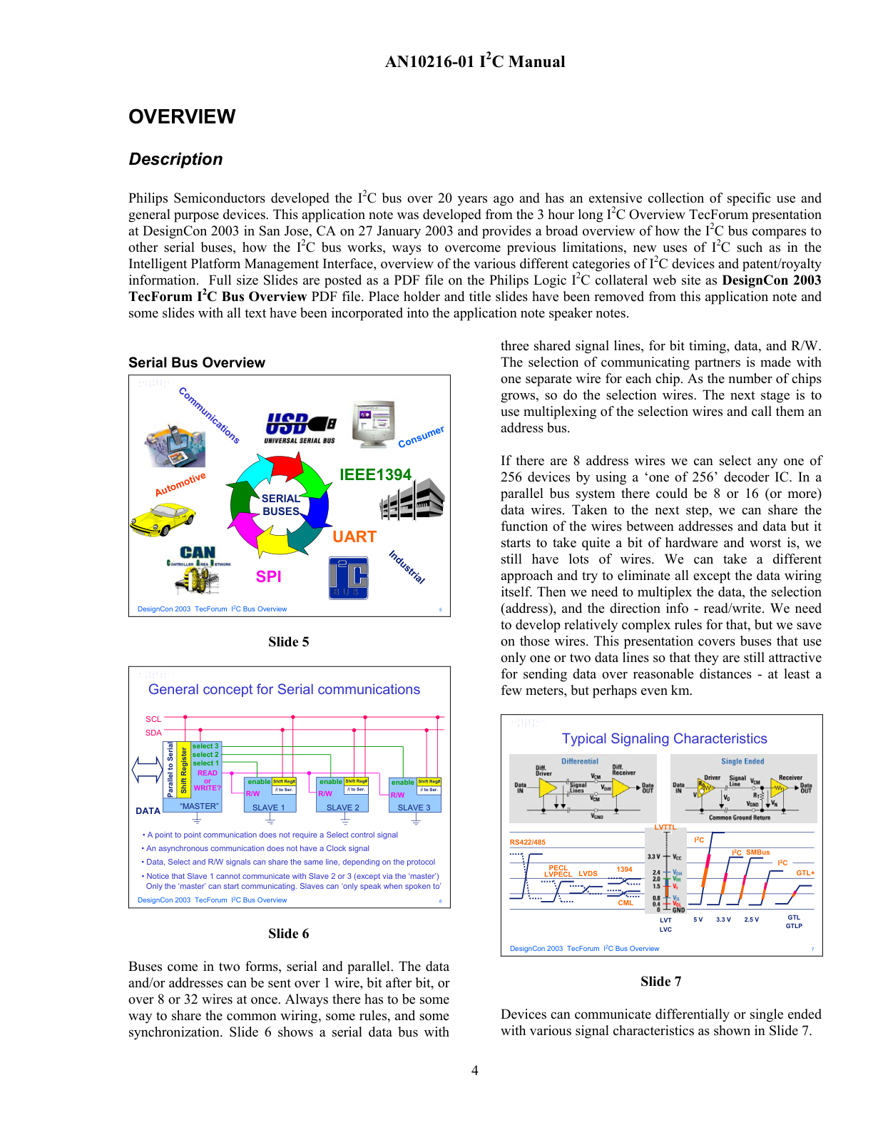
Overview of serial bus families and the general concept of serial communication with a master and multiple slaves sharing the same bus lines (SDA / SCL). I²C sits within the industrial/embedded category alongside SPI.
Every I²C communication follows a master–slave model:
The master (in our project: the XIAO RP2040) initiates all communication, generates the clock signal, and addresses the target device.
The slave (in our project: the SSD1306 OLED display) listens on the bus, responds when its address is called, and receives or sends data accordingly.
Addressing: How Devices Are Identified
Each I²C device has a unique 7-bit address (or 10-bit for larger systems). When the master wants to communicate, it broadcasts the target address on the bus. Every slave listens, but only the one whose address matches responds with an ACK (acknowledge) signal. Devices with the same address would collide — which is why multiplexers exist for systems that require multiple identical devices.
The SSD1306 display used in this project uses the address 0x3C (or 60 in decimal), which is hard-coded in the initialization line: display.begin(SSD1306_SWITCHCAPVCC, 0x3C).
How Data Travels: START, DATA, ACK, STOP
Every I²C transaction follows a fixed structure:
START condition — the master pulls SDA low while SCL is still high. This signals all slaves to listen.
Address + R/W bit — the master sends the 7-bit address of the target slave, followed by a read (1) or write (0) bit.
ACK — the addressed slave pulls SDA low to acknowledge it received the address.
Data bytes — the master (or slave, in a read operation) sends 8-bit data bytes, each followed by an ACK.
STOP condition — the master releases SDA (pulls it high) while SCL is high. The bus is free again.
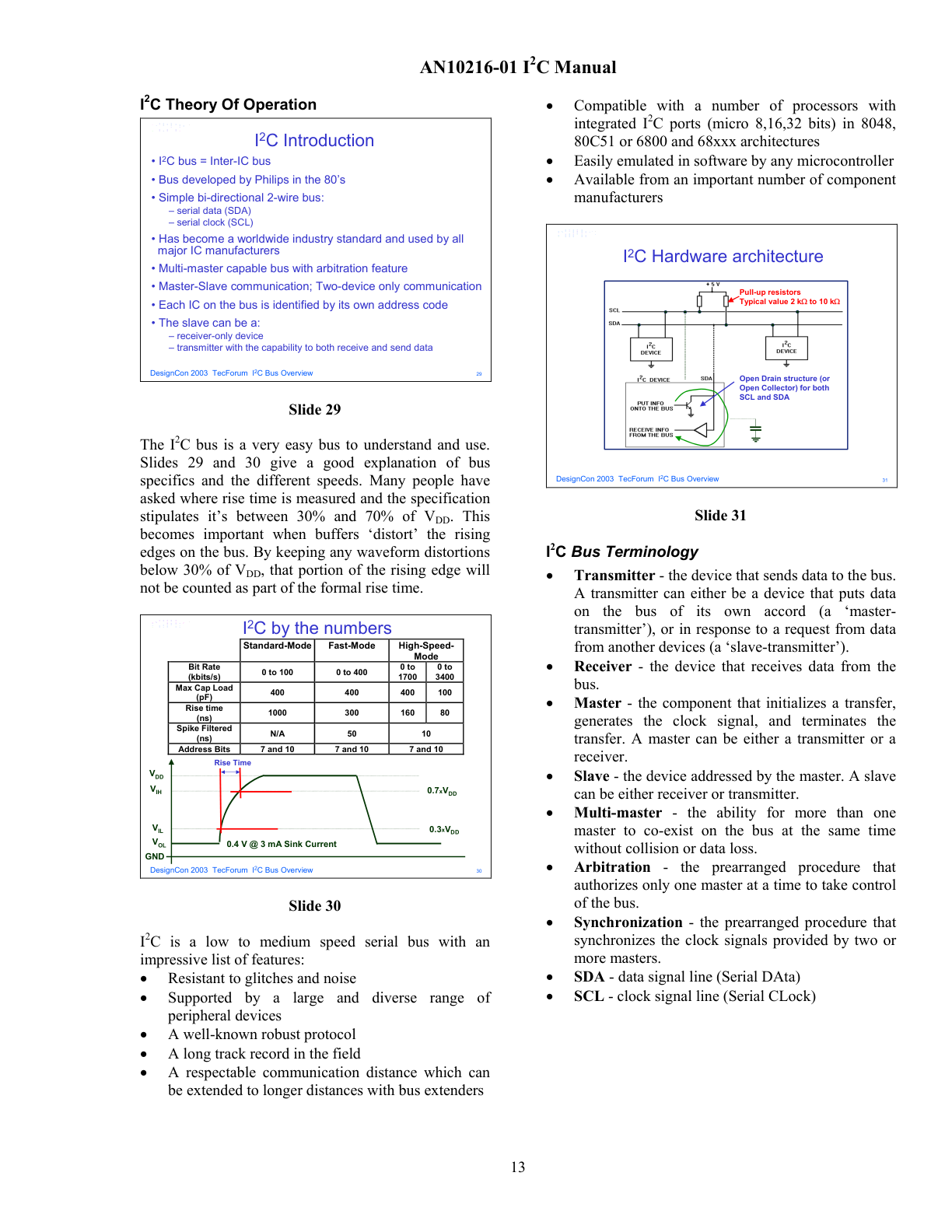
I²C theory of operation: hardware architecture showing open-drain structure with pull-up resistors on SDA and SCL; speed mode specifications (Standard 100 kHz, Fast 400 kHz, High-Speed 3.4 MHz); and key bus terminology — master, slave, transmitter, receiver, SDA, SCL.
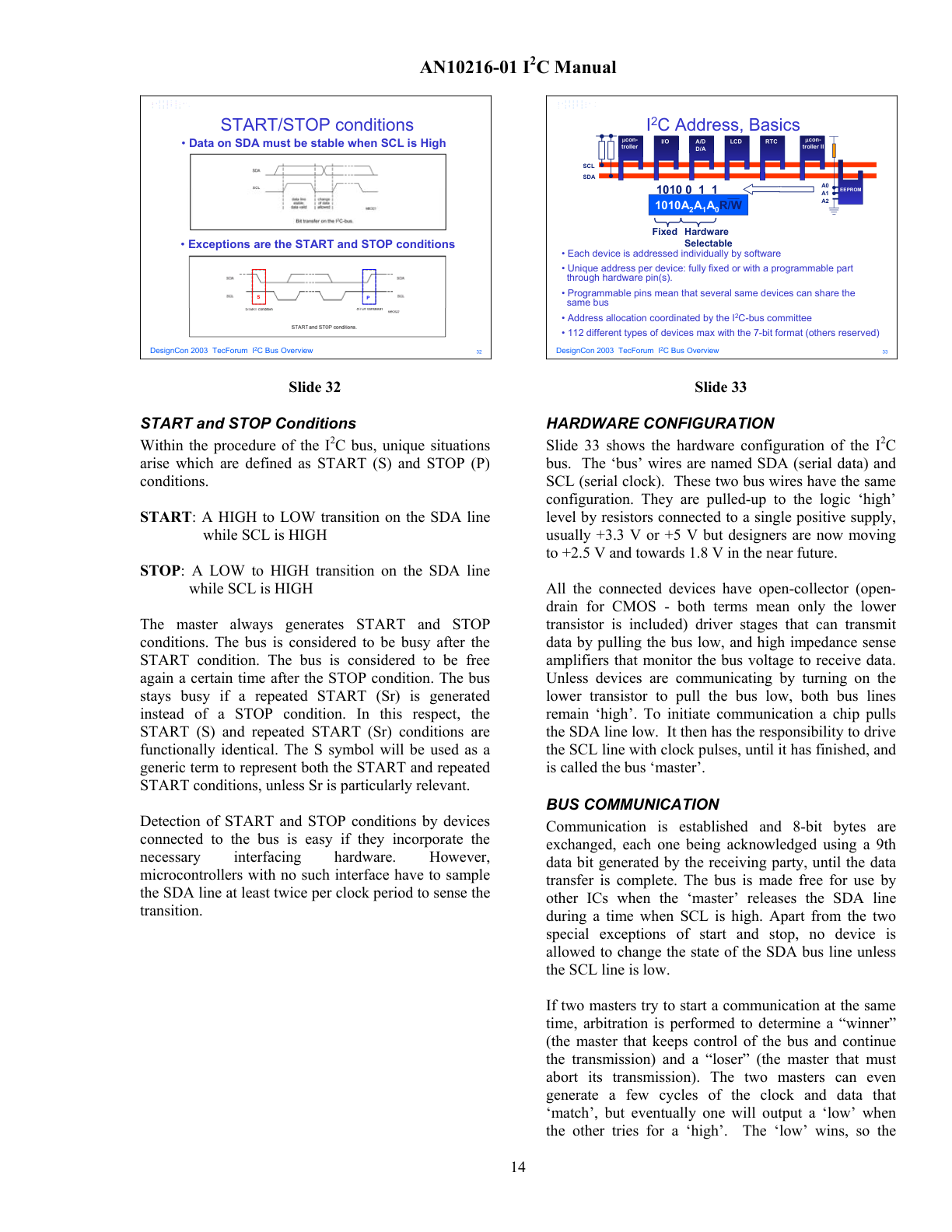
I²C START and STOP conditions (top: signal diagram showing when SDA transitions relative to SCL) and 7-bit addressing format (bottom: the first byte after START contains the slave address and the R/W bit). The SSD1306 OLED display in this project uses address 0x3C.
The SSD1306 OLED display supports Fast mode (400 kHz). The Adafruit library initializes I²C at this speed by default on the XIAO RP2040.
Individual Assignment — Displaying an Image on the OLED via I²C
For the individual assignment I chose to demonstrate I²C communication by sending a bitmap image to an SSD1306 OLED display connected to my XIAO RP2040 board. The image I chose was Snoopy — a recognizable character with enough contrast and detail to make a compelling test for a 128×64 pixel monochrome display.
The complete workflow involved four stages: preparing the image file, converting it to a binary format the display can understand, writing and testing the Arduino code, and finally running the sketch on the physical board.
Step 1 — Choose and Prepare the Image
I started with a PNG file of the Snoopy character — a black-and-white illustration with a clean outline, which is ideal for a monochrome OLED. The display resolution is 128 × 64 pixels, so the image needed to be resized to exactly those dimensions before conversion.
The original Snoopy PNG image selected for the project. The clean black-and-white illustration with a transparent background is well-suited for conversion to a monochrome bitmap for the 128×64 OLED display.
Step 2 — Resize to 128 × 64 px in Paint
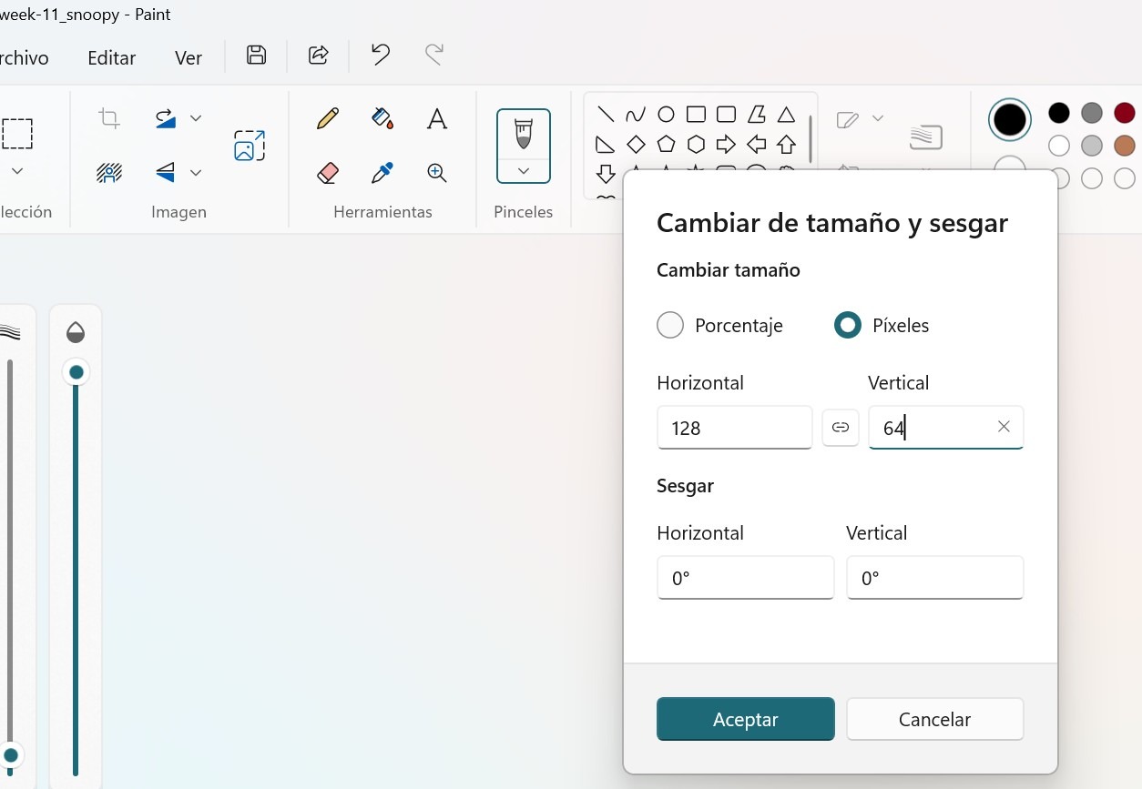
Using Microsoft Paint, I opened the image and used Image → Resize to set the dimensions to exactly 128 pixels wide and 64 pixels tall. I selected "Pixels" as the unit (not percentage) to set the values precisely.
The Paint "Cambiar de tamaño" (Resize) dialog with the dimensions set to 128 × 64 pixels. The "Píxeles" (Pixels) option is selected and aspect ratio lock is disabled to allow free resizing to the exact OLED resolution.
Step 3 — Save as Monochrome BMP
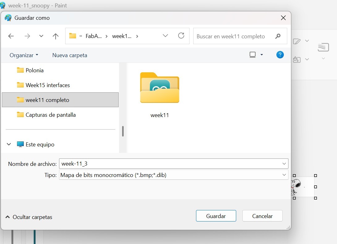
After resizing, I saved the file in Paint using File → Save As → Monochromatic BMP (*.bmp; *.dib). This format stores each pixel as a single bit — 1 (white) or 0 (black) — which is exactly what the SSD1306 display expects. No color data, no compression, just a grid of bits.
The Paint Save As dialog showing the file saved as "week-11_3" with type "Mapa de bits monocromático (*.bmp;*.dib)" — monochromatic bitmap. This format encodes each pixel as a single bit, matching the SSD1306's 1-bit-per-pixel data format.
Step 4 — Convert BMP to Arduino Byte Array (image2cpp)
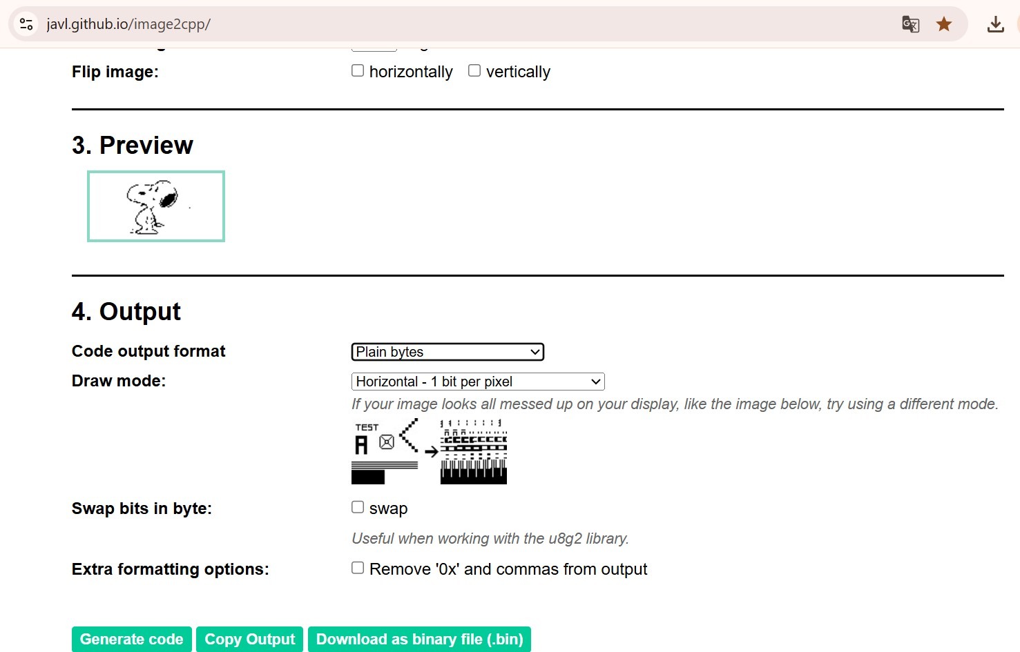
The SSD1306 display cannot accept a BMP file directly — it needs the image encoded as an array of bytes in C/C++ format, stored in program memory (PROGMEM). I used the online tool image2cpp (javl.github.io/image2cpp/) to perform this conversion.
Settings used in image2cpp:
Canvas size: 128 × 64 px (matching the display)
Code output format: Plain bytes
Draw mode: Horizontal — 1 bit per pixel
The tool generates a preview of the image and then produces the hex byte array that goes directly into the Arduino sketch.
The image2cpp tool at javl.github.io/image2cpp/ showing the preview of the Snoopy BMP (step 3) and the output configuration: "Plain bytes" format, "Horizontal — 1 bit per pixel" draw mode. The tool generates the hex byte array ready to paste into the Arduino sketch.
Step 5 — Write the Arduino Sketch
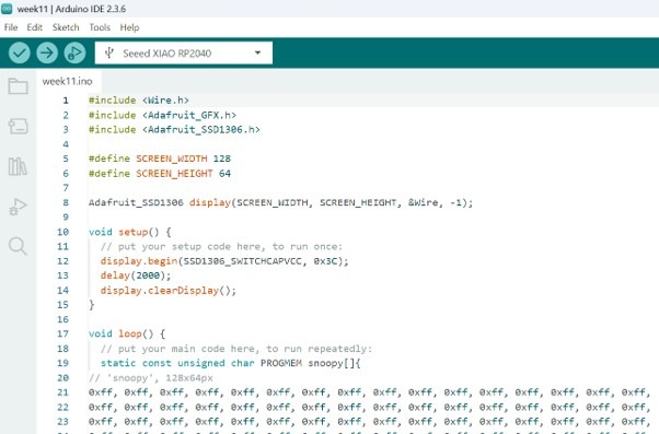
I copied the generated byte array output from image2cpp and pasted it into the Arduino sketch inside a PROGMEM array. The sketch uses three Adafruit libraries:
Wire.h — for I²C communication
Adafruit_GFX.h — graphics primitives
Adafruit_SSD1306.h — SSD1306 display driver
The display is initialized at I²C address 0x3C. In the loop, display.drawBitmap() draws the image starting at pixel (0,0) across the full 128×64 canvas, and display.display() pushes the buffer to the physical screen over I²C.
The Arduino IDE 2.3.6 showing the week11.ino sketch with the Seeed XIAO RP2040 selected as the target board. The snoopy PROGMEM array is visible starting at line 19 — the hex values are the 1024 bytes encoding the 128×64 monochrome bitmap.
Step 6 — Simulate in Wokwi Before Flashing
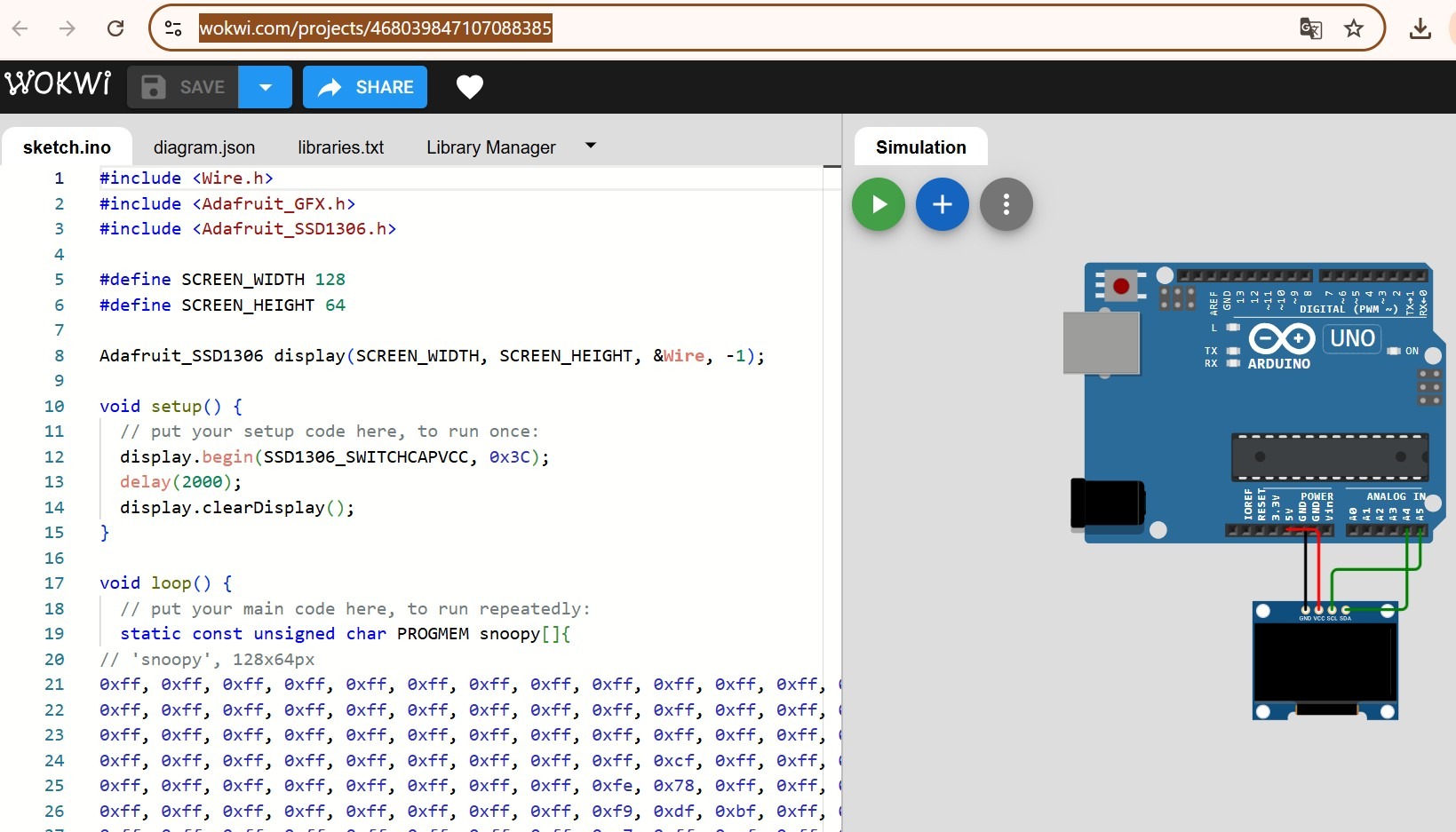
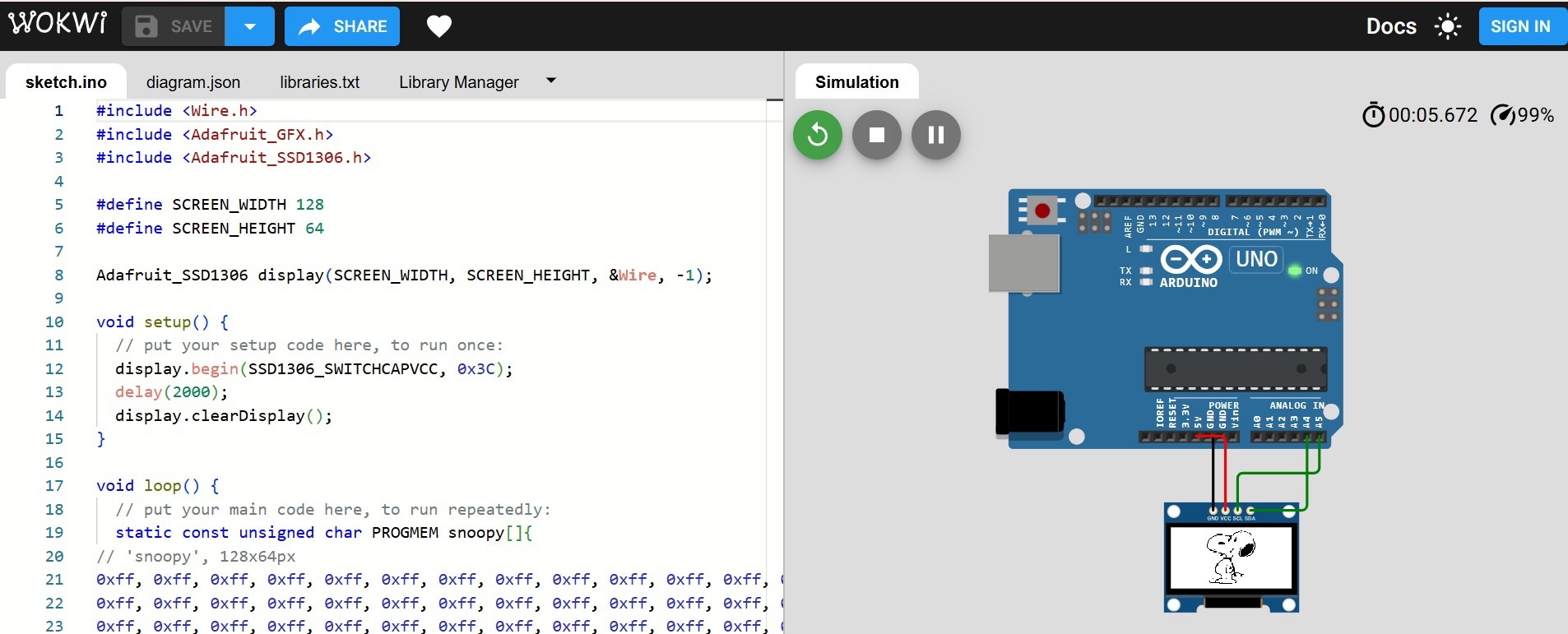
Before uploading to the physical board, I tested the sketch in Wokwi — a browser-based Arduino/RP2040 simulator. Wokwi simulates the I²C bus and the SSD1306 display, making it possible to verify that the image renders correctly without needing the physical hardware.
The Wokwi project included an Arduino Uno (which the simulator uses to run the sketch) connected to an SSD1306 OLED via the simulated I²C pins. The display connection is: VCC → 5V, GND → GND, SCL → A5, SDA → A4.
The Wokwi simulation project before running — the sketch and the simulated Arduino Uno + SSD1306 OLED display connected via I²C. The OLED screen is blank; the simulation has not started yet.
The Wokwi simulation running at 00:05.672 (99% speed). The Snoopy bitmap is correctly rendered on the simulated SSD1306 OLED — confirming that the byte array, draw mode, and I²C initialization are all correct before flashing the physical board.
Step 7 — Flash the XIAO RP2040 and Test on the Physical Board
With the simulation confirmed, I uploaded the sketch to my XIAO RP2040 board using Arduino IDE 2.3.6. The board communicates with the SSD1306 OLED over its hardware I²C pins (SDA on D4, SCL on D5 on the XIAO RP2040). The same I²C address 0x3C and the same byte array work identically on the physical hardware.
The video below shows the board running the sketch and displaying the Snoopy image on the OLED screen in real time:
The XIAO RP2040 displaying the Snoopy bitmap on the SSD1306 OLED display via I²C. The image is transmitted as a 1024-byte array (128×64 pixels × 1 bit/pixel) over the SDA and SCL lines to the display's address 0x3C.
How I²C Works in This Project
Every time the display.display() function is called, the Adafruit library performs the following over the I²C bus:
Sends a START condition on SDA/SCL
Transmits the display address 0x3C with a Write bit
Waits for the display's ACK
Sends the 1024 bytes of image data (128 × 64 pixels ÷ 8 bits/byte)
Sends a STOP condition — the bus is free
This entire transfer happens at up to 400 kHz (Fast mode), meaning the full frame can be sent in approximately 20 ms — fast enough that the image appears instantaneously to the human eye.
Connection summary — XIAO RP2040 → SSD1306 OLED:
XIAO RP2040 Pin
SSD1306 Pin
Function
3.3V
VCC
Power
GND
GND
Ground
D4 (SDA)
SDA
I²C data
D5 (SCL)
SCL
I²C clock
Reflections
This week made the concept of serial communication genuinely tangible for me. Sending an image to a screen over two wires — at high enough speed that it looks instantaneous — is a clear demonstration of what a well-designed protocol can achieve. The I²C standard elegantly solves the problem of how multiple devices share the same physical channel without colliding, using nothing more than a clock, a data line, and a simple addressing convention.
The workflow from PNG image → resized BMP → hex byte array → Arduino code → OLED display also illustrated something important about embedded systems: every data format decision has a reason. The image is monochrome because the display is monochrome. It is 128×64 because that is the display's resolution. The bytes are stored in PROGMEM because flash memory is larger than RAM on the RP2040. Each constraint is a communication between the hardware design and the software.
For my final project (Pitch timer), the Nextion touch display communicates with the XIAO RP2040 over UART rather than I²C — but the underlying principle is the same: a defined protocol, a unique address, and a structured sequence of bytes carrying information between two devices.
Resources