Group assignment
Measure the power consumption of an output device. Document your work on the group work page and reflect on your individual page what you learned.
Individual assignment
Add an output device to a microcontroller board you've designed and program it to do something.
What I knew beforehand
Before this week I had some understanding of how output devices work conceptually — LEDs signal state, displays communicate information, buzzers provide audio feedback. What I had not done before was program all three simultaneously on a single microcontroller board, with each device responding in real time to user input from a touch screen.
An output device is the interface between a system and its user. The quality of that interface determines whether the system is legible — whether a person can understand what it is doing without reading a manual. That framing shaped every design decision I made this week, from the color logic of the LED strip to the layout of the Nextion touch screen.
This documentation was produced in June 2026, during my second and Fab Academy cycle, and represents entirely new work. Programming three output devices simultaneously — the Nextion HMI touch display, the WS2812B LED strip, and the passive buzzer — on a single XIAO RP2040 using a non-blocking millis() state machine was the most complex firmware challenge of my Fab Academy experience. The traffic-light color logic for the LED strip (green → yellow → red as time runs down) was a deliberate design choice rooted in an entrepreneurship principle: a good interface borrows a mental model the user already has, rather than creating a new one. PitchLight's output devices are the only part of the system a presenter ever perceives; everything else is infrastructure. Group assignment
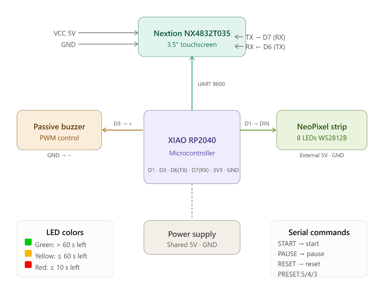
For this assignment I programmed my board — the custom PCB I milled in Week 8 — to control three output devices simultaneously:
Nextion NX4832T035_011 HMI display — 3.5" touchscreen, UART communication at 9600 baud, shows the countdown timer and receives touch events
WS2812B NeoPixel LED strip — 16 addressable RGB LEDs, single-wire NeoPixel protocol on D0, color changes according to time remaining
Passive buzzer — PWM tone at 2 kHz on D1, 5-second alert when countdown reaches zero
System connection diagram for pitch timer. The XIAO RP2040 microcontroller (center) communicates with the Nextion NX4832T035 display via UART at 9600 baud (D6/TX → display RX, D7/RX → display TX). The WS2812B NeoPixel strip (8 LEDs) is driven from D1. The passive buzzer is controlled via PWM on D3. All devices share a common 5V power rail and GND.
Part 1 — Programming the Nextion HMI Display
Nextion displays are programmed using Nextion Editor, a dedicated GUI design tool. Unlike a regular display driver, Nextion runs its own processor — the XIAO only needs to send UART commands to update values on screen and receive events when buttons are touched. The display handles all rendering internally.
Step 1 — Create a New Project: Select Device Model and Orientation
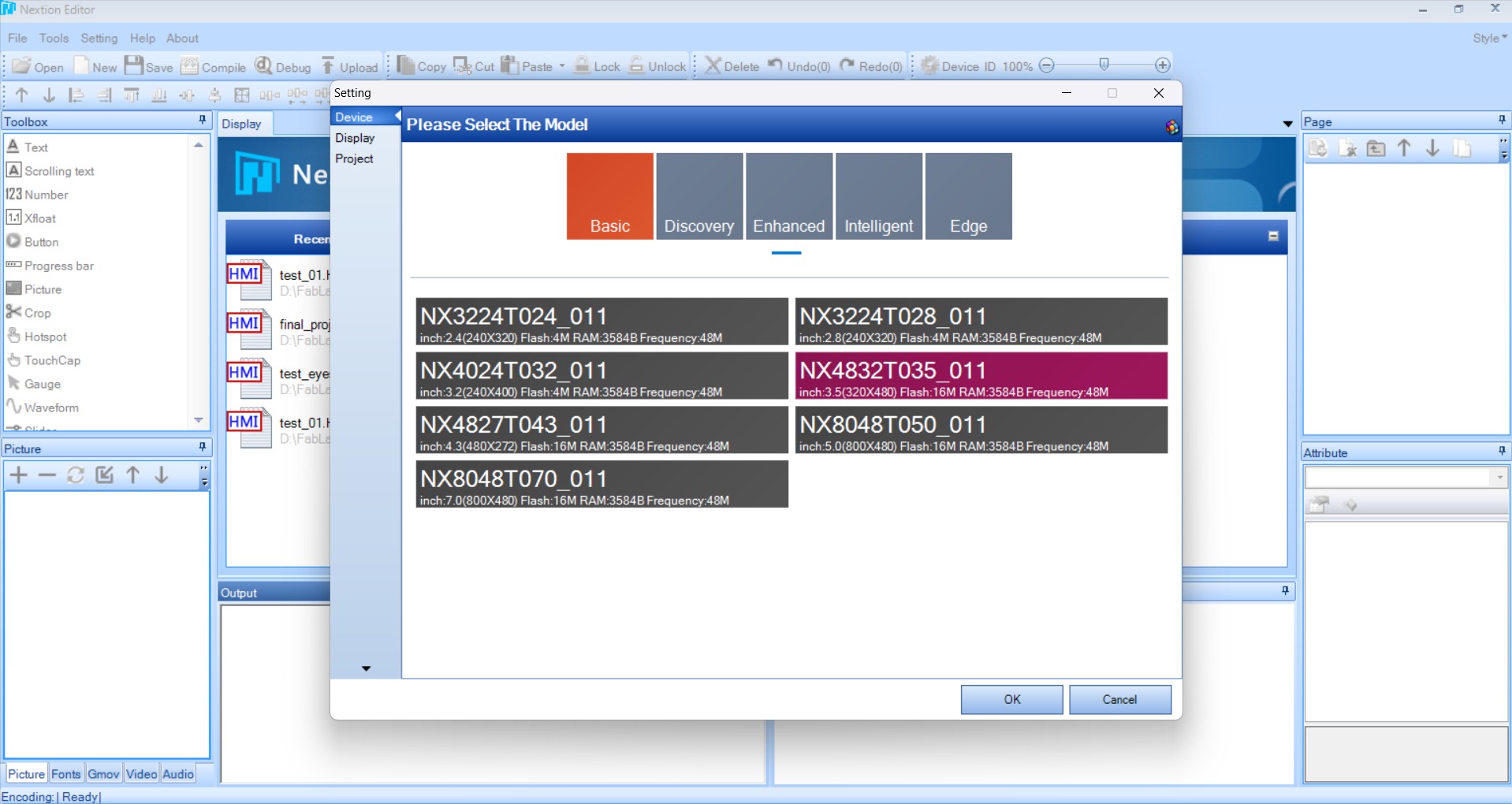
1Setting → Device → Select model: NX4832T035_011
In Nextion Editor I created a new project and opened Setting → Device to select the correct display model. I chose NX4832T035_011 — 3.5 inches, 320×480 pixels, 16 MB Flash, 3584 B RAM, 48 MHz. Selecting the wrong model causes the compiled .tft file to be rejected by the hardware.
Nextion Editor — Setting → Device panel. The model NX4832T035_011 is selected (highlighted in pink): 3.5 inch, 320×480 px, Flash 16M, RAM 3584B, Frequency 48M. Selecting the correct model is essential — the .tft output file is hardware-specific and will not load on a different model.
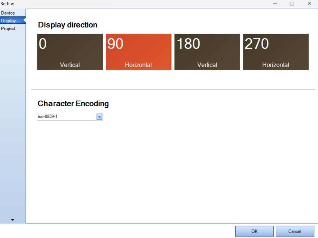
2Setting → Display → Direction: 90° (Horizontal)
Under the Display tab I set the orientation to 90° — Horizontal. This matches the physical orientation of the display in the pitch timer enclosure, where the longer dimension runs left to right. Character encoding was left at iso-8859-1.
Nextion Editor — Setting → Display tab. Display direction set to 90° — Horizontal (highlighted in orange). Character encoding: iso-8859-1. These settings define the canvas dimensions the editor will use and how the display will render in its physical position.
Step 2 — Design the UI: Background Images and Components
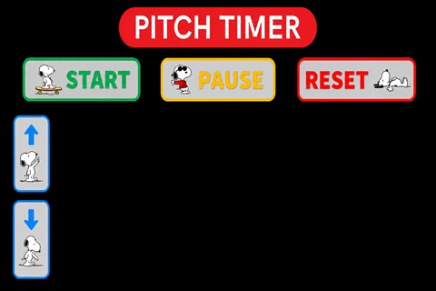
The Nextion UI is built by adding background images and placing interactive components on top. Two background images are required: one for the default state (buttons not pressed) and one for the pressed state (button highlighted). Each image must be resized to exactly 480 × 320 pixels to fill the horizontal canvas.
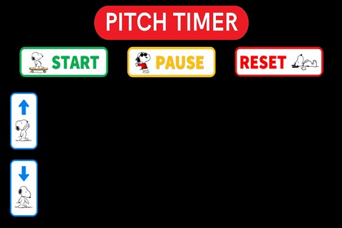
The default state background shows the PITCH TIMER title bar, three buttons (START in green, PAUSE in yellow, RESET in red), and two arrow buttons for preset selection. The pressed-state background shows the same layout with darker button colors to simulate physical feedback.
Default state background (480 × 320 px). Title bar: PITCH TIMER. Three action buttons: START (green), PAUSE (yellow), RESET (red). Two arrow buttons (▲ / ▼) on the left for changing the timer preset between 3, 4, and 5 minutes. The black area at center-right is where the countdown text component (t0) will render.
Pressed state background (480 × 320 px) — same layout with adjusted button shading. Nextion uses two background images to simulate button press visual feedback: the editor swaps between the two backgrounds when the touch event fires. This gives the UI a tactile, responsive feel without requiring individual button state images.
Step 3 — Add Interactive Components
With the backgrounds in place, I added the following components in the Nextion Editor canvas:
From the Toolbox panel I selected Text (T icon) and drew a large rectangle in the center of the canvas. Attributes set in the Attribute panel: objname: t0 · txt: 05:00 · pco: 65535 (white text) · bco: 0 (black background) · xcen: 1 (horizontal center) · ycen: 1 (vertical center). This component is updated every second by the XIAO via UART command t0.txt="MM:SS" followed by three 0xFF bytes.
3bButton components — START, PAUSE, RESET
I added three Button components from the Toolbox and positioned them to align with the button images in the background. For each button I set the object name, text, and a Touch Release event that sends a text command over UART to the XIAO RP2040:
Button
objname
Touch Release event
START
bStart
print "START" · printh 0a
PAUSE
bPause
print "PAUSE" · printh 0a
RESET
bReset
print "RESET" · printh 0a
The printh 0a command sends a newline byte (0x0A) as a command terminator so the XIAO firmware can detect the end of each command string.
Each arrow event also updates vPreset.val and t1.txt locally on the display, so no UART round-trip is needed to update the preset label.
Step 4 — Compile and Upload to the Nextion Display
4File → TFT File Output → copy to microSD → insert and power on
Once all components and events were set, I compiled the project and uploaded it to the physical display using a microSD card:
File → TFT File Output — select output folder. This generates a .tft binary file containing the compiled UI.
Copy the .tft file to a microSD card formatted as FAT32.
Insert the SD card into the Nextion display slot while the display is powered off.
Power on the Nextion — it detects the SD card and loads the .tft file automatically. A progress bar is shown during flashing.
When flashing completes, power off, remove the SD card, and power on again. The UI is now running from internal flash.
Part 2 — XIAO RP2040 Firmware
With the Nextion UI flashed and running, I wrote the Arduino firmware for the XIAO RP2040 that coordinates all three output devices using a non-blocking state machine driven by millis().
The firmware listens for UART commands from the Nextion display, updates the countdown every second, changes the LED strip color based on remaining time, and triggers the buzzer when the timer reaches zero — all simultaneously, without any blocking delay() calls.
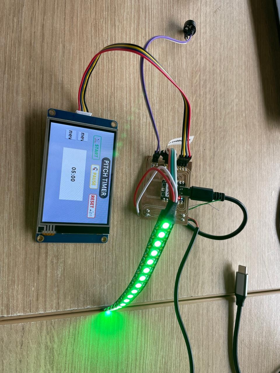
With the Nextion UI flashed to the display and the firmware uploaded to the XIAO RP2040, the complete pitch timer system ran correctly on first boot. The display showed 05:00, the LED strip lit up green, and all three touch buttons responded immediately.
pitch timer fully operational. The Nextion 3.5" HMI touch display (bottom) shows PITCH TIMER with START, PAUSE, and RESET buttons and the 05:00 countdown. The milled PCB with XIAO RP2040 (top) connects to the display via UART and drives the WS2812B LED strip — glowing green, indicating full time remaining. The purple wire connects the passive buzzer.
Reflections
This week crystallized something I had understood theoretically but not yet experienced in practice: the output devices are the only part of an embedded system that a user ever directly perceives. Everything else — the microcontroller, the firmware logic, the PCB traces — is invisible infrastructure. The quality of the interface is what determines whether the system is useful.
Designing the Nextion UI forced me to think about the presentation as a whole experience, not just a technical output. The three-color LED system — green, yellow, red — does not require explanation. It maps onto a cognitive model that everyone already has from traffic lights. That is good interface design: it borrows an existing mental model rather than creating a new one. From an entrepreneurship perspective, this is exactly what a pitch timer for first-time presenters needs: a signal that is legible at a glance, without diverting attention from the audience.