Week_11 Assignments
- Group assignment:
- Individual assignment:
In the group assignment we needed to make two projects to communicate with each others.
In the individual assignment connect nodes with network or bus addresses and local input and output devices.
Group assignment
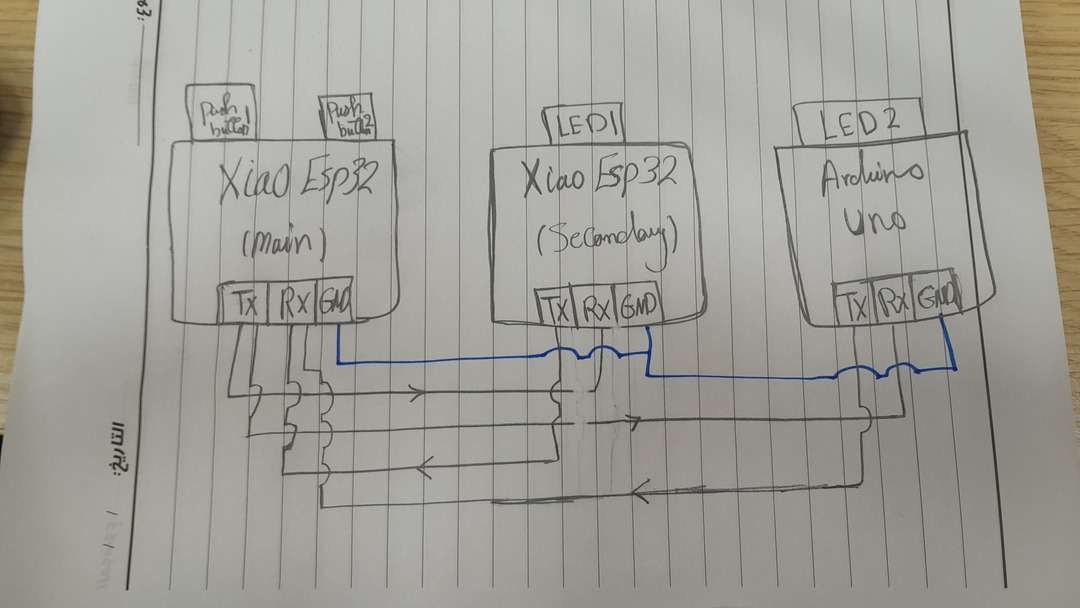
In this assignment we needed to make a project (a board that has an input and output) to communicate with a nother project. I used Xiao ESP32 C3 (the board I designed in week 6 where I added a built-in LED and a pushbutton) with an Arduino Uno R3 with a pushbutton and the built-in LED.
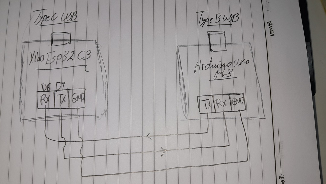
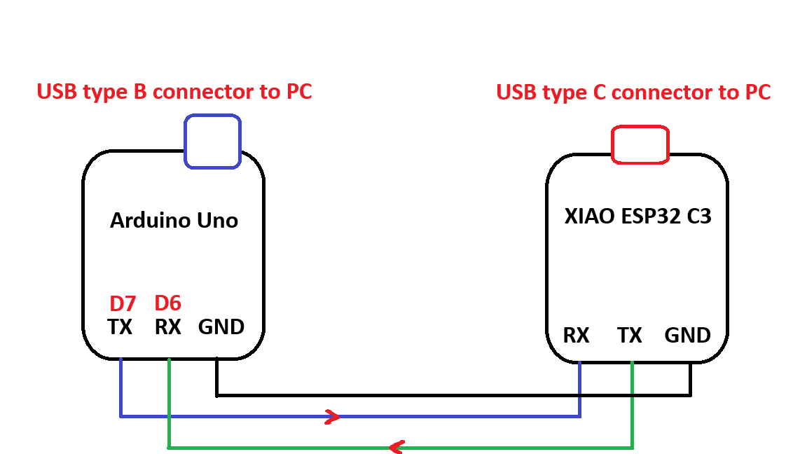
As you can see the wired UART Serial communication can be connected like the picture where the TX pin in one side is connected to the RX pin in the other side. And the GND pin must be connected to GND.
Noting that the triggering voltage to the arduino logic RX varies between 3v and 5v so the TX from the xiao esp 32 (3.3V) can still trigger. On the other hand the arduino TX voltage which is 5V that is sent to the RX in the Xiao ESP32 c3 won't damage it as it can handle this relatively high voltage.
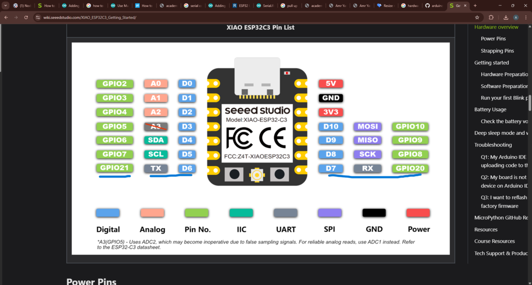
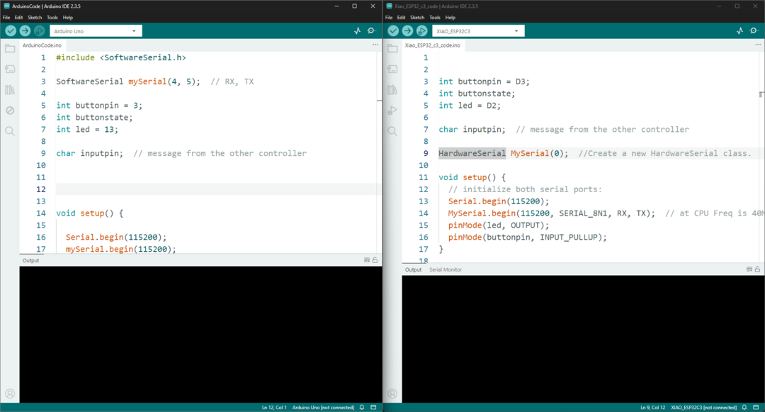
For the Xiao Esp32 C3 I used the HardwareSerial library to configure a communication channel using TX and RX other than the channel used by the USB serial cable. I used the TX and RX channel to communicate with the Arduino Uno and the Serial USB channel to print what I receive from the Arduino.
Here is a flowchart showing the logic of the code.
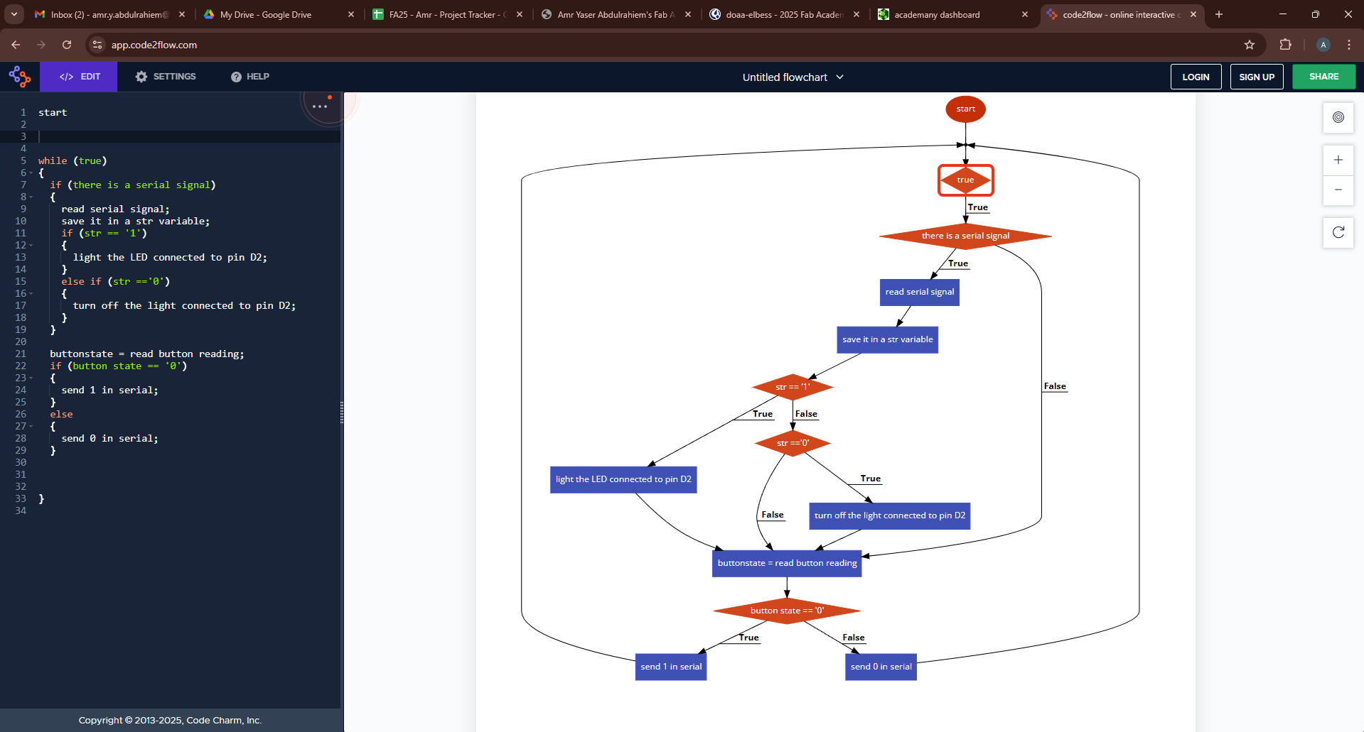
Each decive has the same logic which is waiting for the message on the serial communication and then control a led based on that and also read the push button value ans send a message through serial according to the pushbutton value.
Here you can find the code I ran on the Xiao Esp32 C3:
int buttonpin = D3;
int buttonstate;
int led = D2;

char inputpin;  // message from the other controller

HardwareSerial MySerial(0);  //Create a new HardwareSerial class. The first UART serial configure for the Xiao ESP32 C3
// you can check this tutorial to understand more about the HardwareSerial library

void setup() {
  // initialize both serial ports:
  Serial.begin(115200);
  MySerial.begin(115200, SERIAL_8N1, RX, TX);  // at CPU Freq is 40MHz, work half speed of defined. RX and TX refers to pins 20 and 21 in Xiao ESP32 C3.
  pinMode(led, OUTPUT);
  pinMode(buttonpin, INPUT_PULLUP);
}

void loop() {
  // read from port 1, send to port 0:
  if (MySerial.available()) {
    char str = MySerial.read();
    Serial.print("I received from Arduino > ");
    Serial.println(str);
    // while (Serial.available())
    if (str == '1') {
      digitalWrite(led, 1);
    } else if (str == '0') {
      digitalWrite(led, 0);
    }
  }
  buttonstate = digitalRead(buttonpin);
  if (buttonstate == 0) {
    MySerial.print('1');
    delay(10);

  } else {
    MySerial.print('0');
    delay(10);
  }
}
For the arduino I did the same but used SoftwareSerial library where I can configure two pins to act like TX and RX and a channel to receive and send to the Xiao and I used the default serial to print what I receive from the Xiao.
#include <SoftwareSerial.h>

SoftwareSerial mySerial(4, 5);  // RX, TX

int buttonpin = 3;

int buttonstate;

int led = 13;

char inputpin;  // message from the other controller

void setup() {

    Serial.begin(115200);
    mySerial.begin(115200);
    pinMode(buttonpin, INPUT_PULLUP);
    pinMode(led, OUTPUT);
    }

void loop() {

    while (mySerial.available()) {
        inputpin = mySerial.read();
        Serial.print("I received from xiao > ");
        Serial.println(inputpin);
        if (inputpin == '1') {
            digitalWrite(led, 1);
            } else if (inputpin == '0') {
                digitalWrite(led, 0);
            }
            }

    buttonstate = digitalRead(buttonpin);
    if (buttonstate == 0) {
        mySerial.print('1');
        delay(10);

        } else {
        mySerial.print('0');
        delay(10);
            }
        }
The I uploaded these codes and VIOLA ! it worked.
Individual assignment
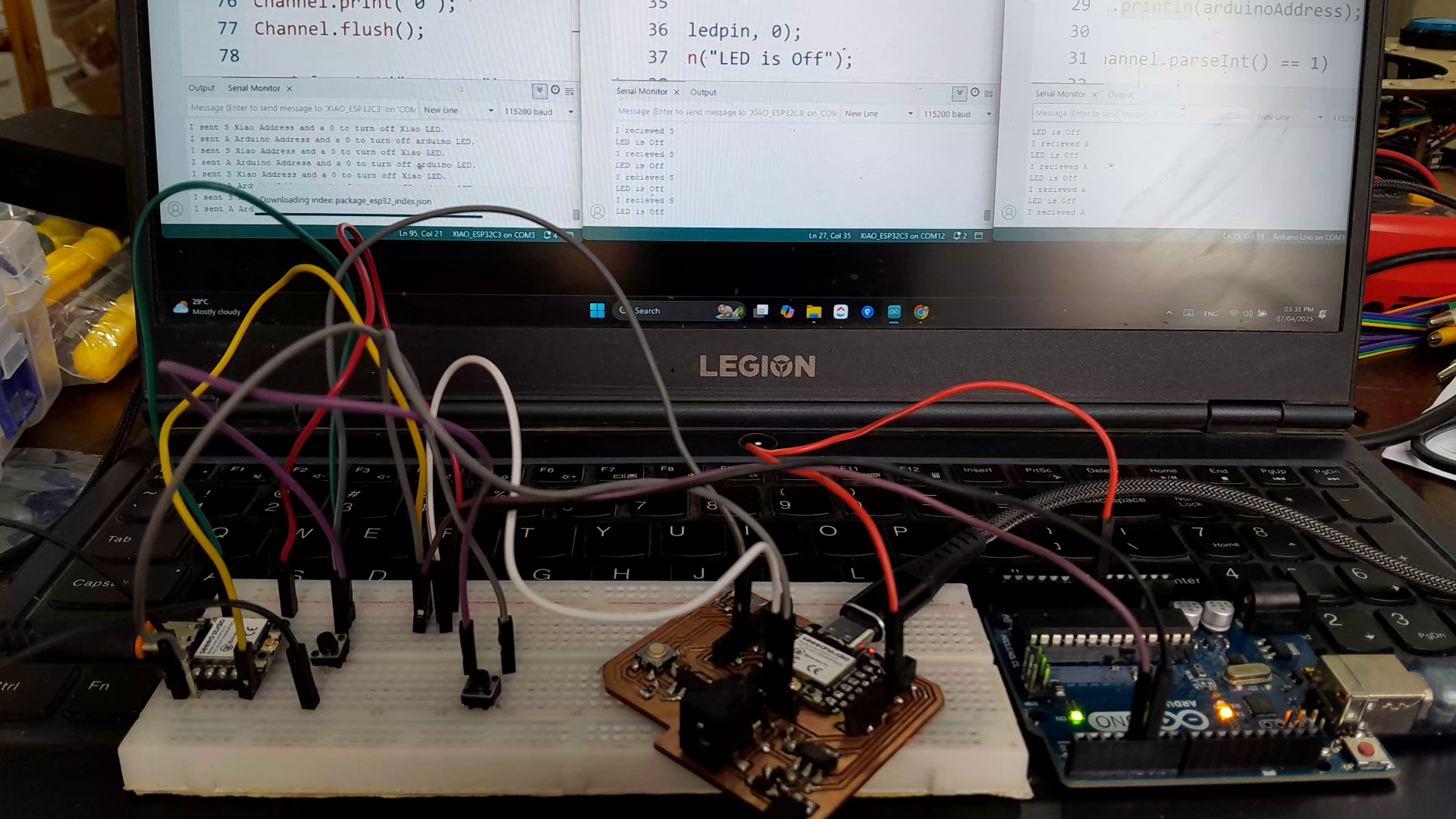
For the individual assignment I used three boards a main Xiao_ESP32_c3 board, a secondary Xiao_ESP32_c3 and an Arduino Uno board as a secondary one too. All boards are connected using Serial communications.
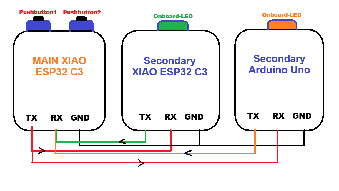
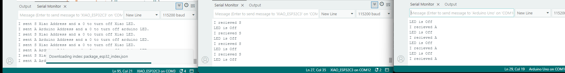
The project makes the main board sends a message contains an address and a value when using one of the push button. When a board receives its address and the value it controls a LED whether to turn it on or off according to the value.
I used a HardwareSerial port in both the main and the secondary Xiao_ESP32_c3 and SoftwareSerial in the Arduino uno to communicate with each other called 'Channel'. And used the Serial library to make each one of the boards communicate with the Serial monitor "my PC" to show in the serial monitor what it sends in case of the main board and what it receives in the cases of the Secondary boards.
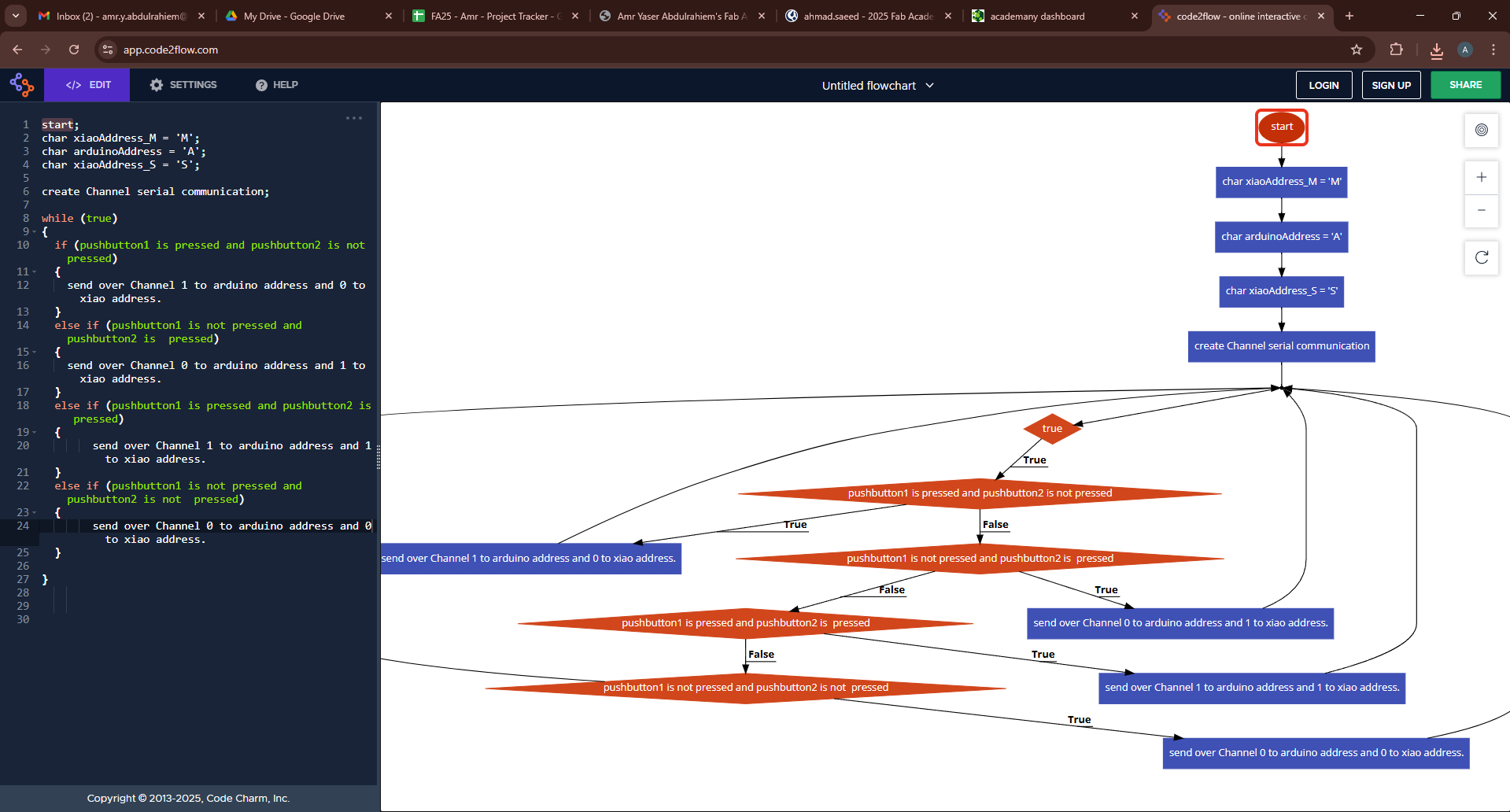
Here is a flowchart for the main board that shows the mainboard sends messages depending on the start of the pushbuttons.
Main board code:
    #include <HardwareSerial.h>

      HardwareSerial Channel(0);

      int pushbuttonpin = D1;
      int pushbuttonvalue;

      int pushbuttonpin2 = D2;
      int pushbuttonvalue2;

      char message;

      char xiaoAddress_M = 'M';
      char arduinoAddress = 'A';
      char xiaoAddress_S = 'S';


      void setup() {
        Serial.begin(115200);
        Channel.begin(115200,SERIAL_8N1, RX, TX);
        pinMode(pushbuttonpin, INPUT_PULLUP);
        pinMode(pushbuttonpin2, INPUT_PULLUP);
        // put your setup code here, to run once:
      }

      void loop() {
        pushbuttonvalue = digitalRead(pushbuttonpin);
        pushbuttonvalue2 = digitalRead(pushbuttonpin2);

        if (pushbuttonvalue == 0 && pushbuttonvalue2 == 1)
        {
          //send 1 to the arduino on its address
          Channel.print(arduinoAddress);
          Channel.print('1');
          Channel.flush();
          Channel.print(xiaoAddress_S);
          Channel.print('0');
          Channel.flush();

          Serial.print("I sent ");
          Serial.print(arduinoAddress);
          Serial.println(" Arduino Address and a 1 to turn on arduino LED.");

          Serial.print("I sent ");
          Serial.print(xiaoAddress_S);
          Serial.println(" Xiao Address and a 0 to turn off Xiao LED.");

        }
        else if (pushbuttonvalue == 1 && pushbuttonvalue2 == 0)
        {
          Channel.print(xiaoAddress_S);
          Channel.print('1');
          Channel.flush();
          Channel.print(arduinoAddress);
          Channel.print('0');
          Channel.flush();

          Serial.print("I sent ");
          Serial.print(xiaoAddress_S);
          Serial.println(" Xiao Address and a 1 to turn on Xiao LED.");

          Serial.print("I sent ");
          Serial.print(arduinoAddress);
          Serial.println(" Arduino Address and a 0 to turn off arduino LED.");


        }
        else if (pushbuttonvalue == 1 && pushbuttonvalue2 == 1)
        {

          Channel.print(xiaoAddress_S);
          Channel.print('0');
          Channel.flush();
          Channel.print(arduinoAddress);
          Channel.print('0');
          Channel.flush();

          Serial.print("I sent ");
          Serial.print(xiaoAddress_S);
          Serial.println(" Xiao Address and a 0 to turn off Xiao LED.");

          Serial.print("I sent ");
          Serial.print(arduinoAddress);
          Serial.println(" Arduino Address and a 0 to turn off arduino LED.");

        }
        else if (pushbuttonvalue == 0 && pushbuttonvalue2 == 0)
        {
          Channel.print(xiaoAddress_S);
          Channel.print('1');
          Channel.flush();
          Channel.print(arduinoAddress);
          Channel.print('1');
          Channel.flush();
        }

        /*
        Serial.print("button value =   ");
        Serial.print(pushbuttonvalue);
        */
        /*
        if (Serial.available())
        {
          message = Serial.read();
          Serial.flush();
          if (message!= '\n' && message != '\r')
          {
            Serial.print("I received this massage from your PC >    ");
            Serial.println(message);

          }
        }
        */
        // put your main code here, to run repeatedly:

        delay(10);

      }
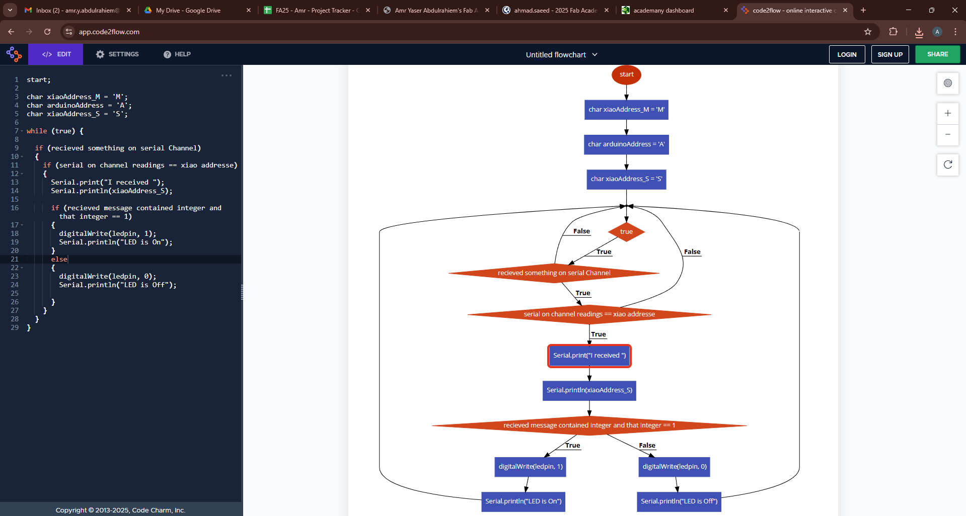
Here you van see the secondary boards (Arduino uno and Xiao esp32 c3) logic in a flowchart where each one of then receives address and a value that controls the on-board LEDs.
Secondary Xiao_ESP32_c3 code:
    #include <HardwareSerial.h>

      HardwareSerial Channel(0);


      char xiaoAddress_M = 'M';
      char arduinoAddress = 'A';
      char xiaoAddress_S = 'S';

      int ledpin = D2;

      void setup() {
        Serial.begin(115200);
        Channel.begin(115200,SERIAL_8N1, RX, TX);
        pinMode(ledpin, OUTPUT);
        // put your setup code here, to run once:

      }

      void loop() {

        if (Channel.available())
        {
          if (Channel.read() == xiaoAddress_S)
          {
            Serial.print("I received ");
            Serial.println(xiaoAddress_S);

            if (Channel.parseInt() == 1)
            {
              digitalWrite(ledpin, 1);
              Serial.println("LED is On");
            }
            else
            {
              digitalWrite(ledpin, 0);
              Serial.println("LED is Off");

            }
          }
        }


        // put your main code here, to run repeatedly:

      }
Secondary Arduino Uno code:
    #include <SoftwareSerial.h>

      SoftwareSerial Channel(4,5); //Rx and TX pins

      char xiaoAddress_M = 'M';
      char arduinoAddress = 'A';
      char xiaoAddress_S = 'S';

      int ledpin = 13;

      void setup() {
        Serial.begin(115200);
        Channel.begin(115200);
        pinMode(ledpin, OUTPUT);
        // put your setup code here, to run once:

      }
      void loop() {

        if (Channel.available())
        {
          if (Channel.read() == arduinoAddress)
          {
            Serial.print("I received ");
            Serial.println(arduinoAddress);

            if (Channel.parseInt() == 1)
            {
              digitalWrite(ledpin, 1);
              Serial.println("LED is On");
            }
            else
            {
              digitalWrite(ledpin, 0);
              Serial.println("LED is Off");
            }
          }
        }
        // put your main code here, to run repeatedly:

      }
Hero shot for the circuit:
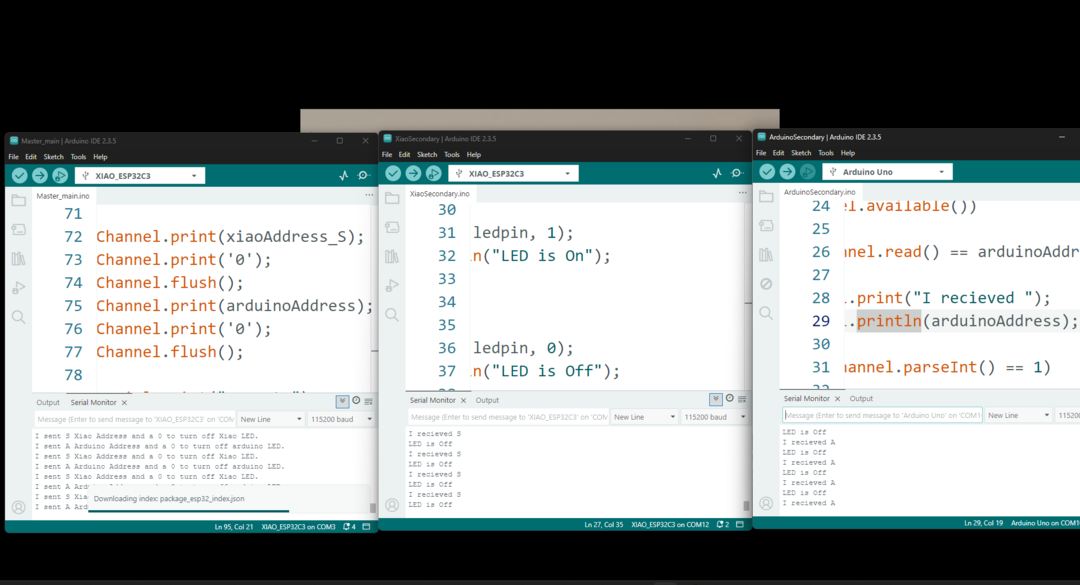
Sending data to the Arduino board:
Sending data to Secondary Xiao_ESP32_c3 board: