
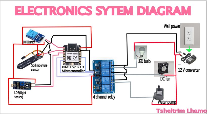
My final project is the COSMIC PEPPER PIG which is a smart automated system for pepper growth. It will take in 2 inputs: soil moisture and temperature and its designated corresponding outputs will be: a fan, a water pump and an OLED to display the real time data. I will be using Xiao ESP 32 c3 as the microcontroller. To make this project fun and interesting for myself, I designed the enclosure similar to a cosmic pig. Check it out.
Check out the final showcase of it here
My Final Project Development-Week01
Have you ever seen a school that is a fortress, known locally as a Dzong? In Bhutan, where His Majesty continually emphasizes the importance of innovation and technology. That's why a school was built in Pangbisa, Paro, which does not undermine our values and principles, however it meets modern standard. That is where I am studying right now. I know, i know I am blessed and fortunate to be here and no words are not enough to express the depth of my gratitude.
My high school is on top of a mountain, so it's always cold and windy. This year, they introduced greenhouses and hydroponics, and I got really excited to get involved because I saw a chance to make things even better. Growing crops in our cold, mountainous region is tough, but what if we could create a greenhouse that adapts to the environment?
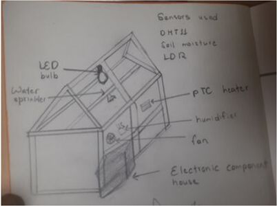
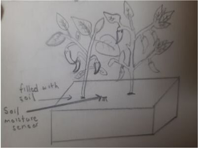
In Bhutan, Ema Datshi—the beloved chili and cheese stew, a favorite dish among both locals and tourists—is more than just a meal; it’s a cultural staple that holds a cherished place in every household. Chilies[locally known as Aema] and spices are not just ingredients—they’re a crucial part of our culture and daily life. Most Bhutanese dishes are incomplete without a generous addition of chili, which is deeply rooted in our culinary traditions. Recognizing this, I wanted to create a Smart Automated Greenhouse specifically designed to cultivate chili under optimum conditions. This system ensures the ideal temperature, humidity, and soil moisture for the chili plants, allowing them to thrive even in challenging cold mountains.
Thus I came up with my final project idea. My goal is to design a self-sustaining greenhouse that regulates temperature, humidity, and soil moisture through sensor-based automation, solar-powered heating, and smart irrigation. This project allows me to integrate 2D and 3D design, additive and subtractive fabrication, embedded programming, and system integration—pushing my skills across multiple domains.
Week02 Progress
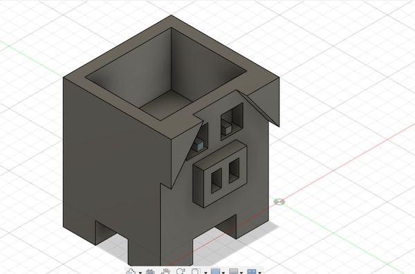
During this week's local session, Rico suggested adding a fun twist to my greenhouse project instead of the typical house-like design. Inspired by this, I decided to create an animal carrying my greenhouse(Aema Chhim) and while exploring I wanted to create a rough model and this link, has been of great help to me. For that I needed to learn the basics of Fusion360.
Week04 Progress-Embedded Programming
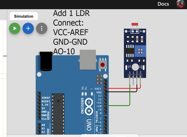
During this week we learned circuit simulation and browsed through the datasheet for our micro controllers. To make tiny little baby steps, I followed a tutorial, and simulated a circuit that prints the readings from the LDR[Light Dependent Resistor.]
Firstly go to Wowki and choose Arduino Uno and start from scratch
Then press on the plus button and add an LDR
Connect the following terminals as given in the diagram
Then when you press on the red box that is circled, you can manipulate the illumination so the readings would be different.
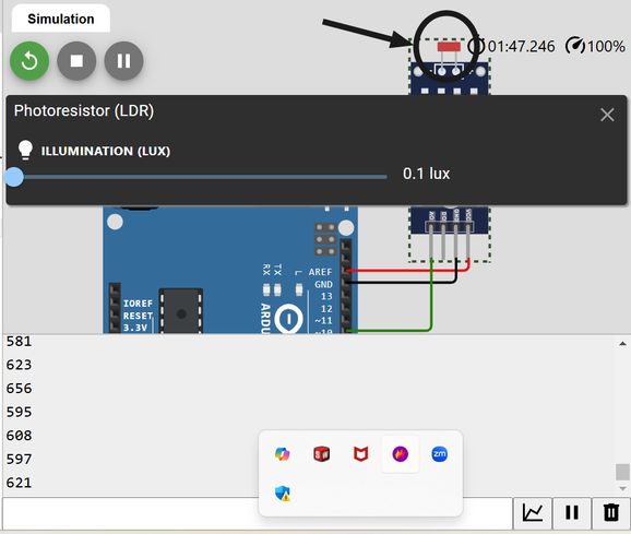
We have to connect AO to a GPIO because our data is analogue and is continuous. While coding too, we have to set that GPIO as our INPUT. The code that I wrote after watching the tutorial is given below:
NOTE: I asked AI[chatgpt] to write me the code to enclose the following code into a clickable button. I copied the code and pasted it in the chat and the prompt was "Modify the code to enclose the following in a clickable button that will open and hide it when clicked."
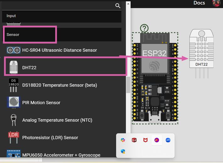
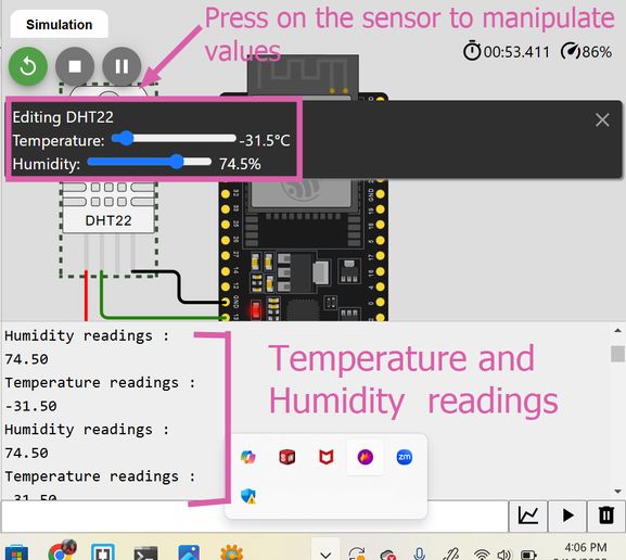
Then i also wanted to try simulating the DHT22 sensor and for that I referred to this tutorial. This time instead of Arduino Uno board, I chose to work on ESP32.
Firstly presss the plus(+) button and then scroll down to inputs and select DHT22 sensor.
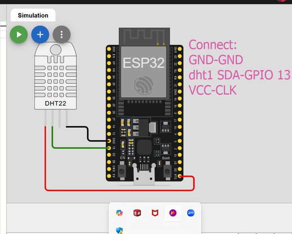
Next connect the following.
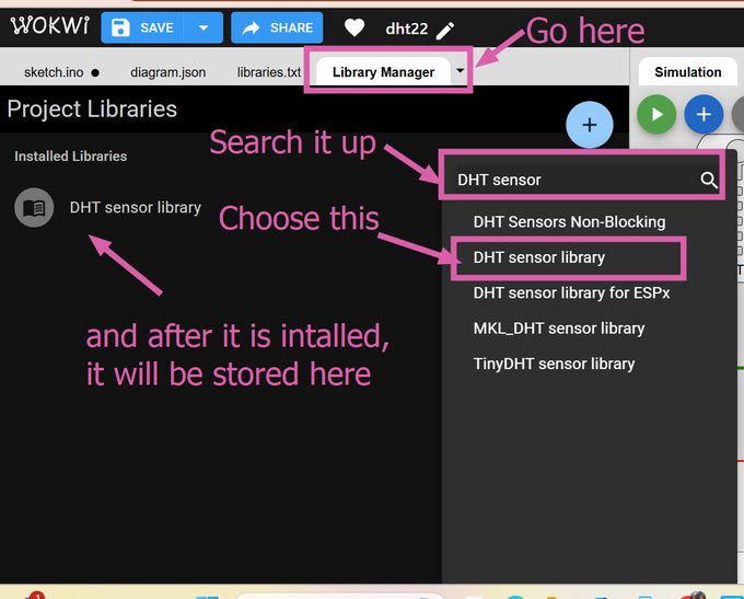
Then go to the library manager and search up DHT sensor and then download DHT sensor library and then it will be installed. The library provides predefined functions to make communication with the sensor easier.
When you press on the sensor, you will be able to manipulate the humidity and temperatures value.
Then you can simulate it and the temperature and the humidity readings will be displayed.
NOTE: I asked AI[chatgpt] to write me the code to enclose the following code into a clickable button. I copied the code and pasted it in the chat and the prompt was "Modify the code to enclose the following in a clickable button that will open and hide it when clicked."
Week 05 Progress!
This week our local instructor assigned each of us our support instructors[fab academy students who have graduated last year] and I got 2 great mentors for fab academy namely Ngawang Pemo Dukpa and Yangtshel Wangyel. Then I went through their websites and in azhim Ngawang's website, I saw that she created a pseudocode to understand the workflow of her project better and then i thought why not do it myself. Then I gave the AI-Chatgpt this prompt, "Generate a pseudocode for an automated greenhouse using various sensors and actuators, including DHT22, Light Sensor (LDR), Soil Moisture Sensor, and actuators like Heater, Water Pump, and ventilation system. The main loop should read sensor data send the information to the microcontroller and decide whether to activate or deactivate actuators based on sensor thresholds while including a delay for the next cycle.
However then I had to edit some of it myself because I did not find it satisfactory as instead of saying activate fan if the temperature is too high, it said to activate ventilation which was kinda vague. Otherwise it did a great job
BEGIN

    // Initialization
    Initialize Temperature Sensor (DHT22)
    Initialize Light Sensor (LDR)
    Initialize Soil Moisture Sensor
    Initialize Actuators (Heater, Water Pump, Fan)
    Initialize Display/Control Interface

    // Main Loop
    WHILE system is running DO

        // Read Sensor Data
        temperature <- Read Temperature Sensor (DHT22)
        humidity <- Read Humidity Sensor (DHT22)
        light_level <- Read Light Sensor (LDR)
        soil_moisture <- Read Soil Moisture Sensor

        // Control Logic
        IF temperature < MIN_TEMPERATURE THEN
            Activate Heater
        ELSE IF temperature > MAX_TEMPERATURE THEN
            Deactivate Heater
            Activate Fan
        ENDIF

        IF humidity < MIN_HUMIDITY THEN
            Activate Humidifier (if available)
        ELSE IF humidity > MAX_HUMIDITY THEN
            Activate Fan
        ELSE
            Deactivate Fan
        ENDIF

        IF soil_moisture < MIN_SOIL_MOISTURE THEN
            Activate Water Pump for IRRIGATION_TIME
        ELSE
            Deactivate Water Pump
        ENDIF

        // Display Data
        Display Temperature, Humidity, Light Level, and Soil Moisture on LCD/Interface

        // Wait for next cycle
        Delay(SYSTEM_UPDATE_INTERVAL)
    ENDWHILE

END
Cardboard prototype
Moreover we were suggested to create a cardboard prototype to help us visualize our design by providing valuable insights into our project's functionality.
This prototype took me about 5 hours to create. This activity has helped me understand the structural and functionalities of my design better. Thus I would recommend everyone to create fast cardboard prototype initially as it helps a lot.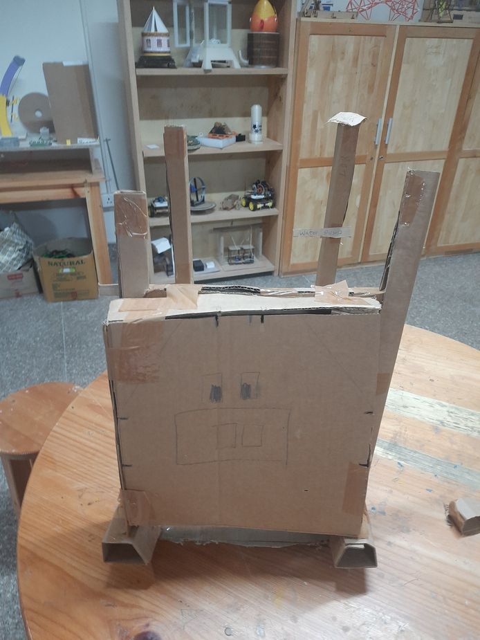
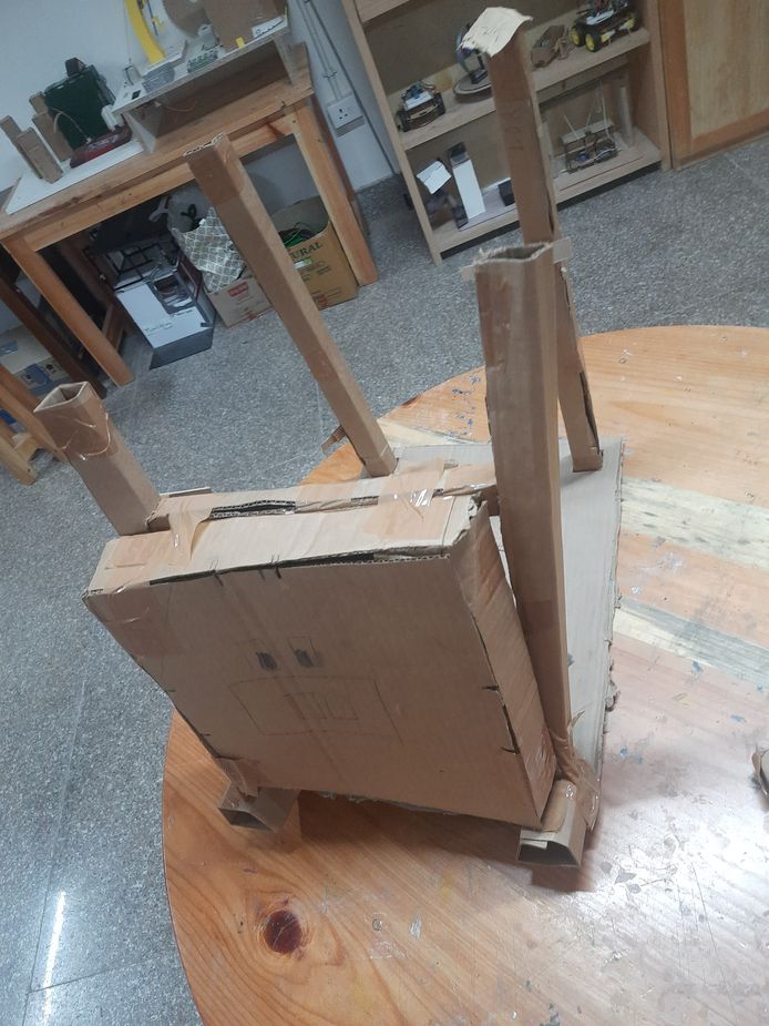
My design consists of a flat base with four square holes at the corners, each measuring 3 cm wide and spaced 2 cm apart along the x and y axes. Four 3 cm × 3 cm columns are inserted into these holes, and elevate the base by 5 cm. Then I created a 3D box and added facial features to resemble a pig. To enhance stability, I placed a horizontal column between two upright columns for additional support. Next, I added 2 small cubes of dimensions 5 cm x 5cm x 5cm on the base where the horizontal column was placed and positioned the pig's face on it. Finally, I used duct tape to secure all the components together.
But I think I have realized the flaws in my design so i wil be creating another cardboard prototype soon.
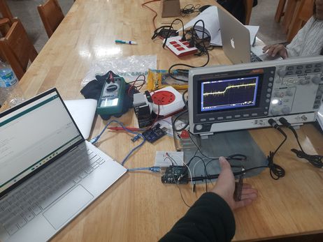
Week 06- Testing soil moisture sensor with Breadboard
This week was Eletcronics Designing and to learn about machiens such as oscilloscope and multimetre in our lab. So me and Dawa and Yangtshel connected the jumper wires to the breadboard, resistor, led and the arduino board. Then we asked AI-chatgpt to generate a code for arduino uno interacting with a soil moisture sensor and to blink the led if it is below a ceratin threshold. Then we connected it to the signal and GND of oscilloscope and observed it and WOW!!! It helped me visualize it better.
 br
br
This is a video of it. The surge in the oscilloscope indicates that the soil moisture sensor has detected more moisture. We connected the FTDI with a USB cable to my pc and opened Arduino Ide and then copied and pasted the code there, then we went to sketch > Upload > Arduino Uno and then the code was sent there.
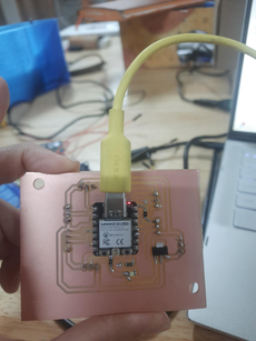
Week 08: 1st Final Project Board
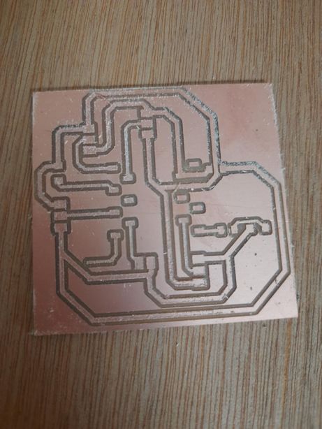
Yipee! I was able to mill my final project board though my instructors guarantee that this wont be my final project board. This was to just give me a gist of the upcoming process and problems I will be facing heads on-like a bull😹😹😹
I performed the continuity test and soldered some of the components together. The pinsockets were designed for a soil moisture, a dht22, a dc motor and 3 relays.
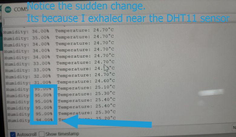
Week 09: Testing DHT11 sensor: inputs
During the electronics design week, I tested a soil moisture sensor with arduino Uno. This time, I tested DHT11 sensor with my very own board!! and the readings were displayed in the serial monitor.I accidentally burnt 1 dht sensor because I confused the VCC and the GND wires and connected them in the wrong positions. It heated my dht and then the dht stopped functioning so I switched to another 1 and carefully handled it this time
Capacitive soil moisture sensor
Recollection: During the electronics design week, I tested a soil moisture sensor with arduino Uno. This time, I tested the soil moisture sensor with my very own board!!
A capacitive soil moisture sensor is a device used to measure the moisture level in soil by detecting changes in the capacitance (electrical charge storage) between two conductive plates inserted into the soil. The principle behind it is based on the fact that water in the soil changes the dielectric constant, and this alters the capacitance between the plates.
They are also more durable. It has 3 pinouts designated for VCC, GND and signal pin. Be careful of the connections!
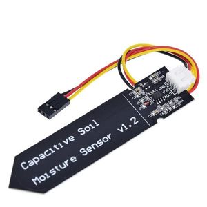
Image source
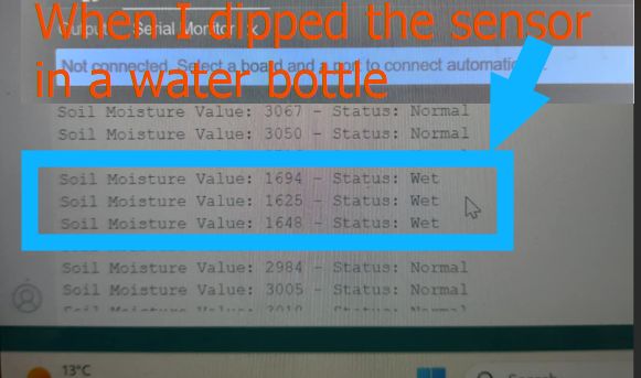
I asked chatgpt to give me a code suitable for this project with the prompt "Write an Arduino program to read a soil moisture sensor connected to GPIO pin 2. Display the moisture value and classify it as 'Wet' if the value is below 1800, or 'Normal' if the value is above 1800. The result should be printed to the serial monitor every second." and then I asked it to explain the outputs in the serial monitor.
const int soilMoisturePin = 2; // GPIO 2
void setup() {
  Serial.begin(115200);
  delay(1000);
  pinMode(soilMoisturePin, INPUT);
}

void loop() {
  int moistureValue = analogRead(soilMoisturePin);

  Serial.print("Soil Moisture Value: ");
  Serial.print(moistureValue);
  Serial.print(" - Status: ");

  // Wet or Normal classification
  if (moistureValue < 1800) {
    Serial.println("Wet");
  } else {
    Serial.println("Normal");
  }

  delay(1000);
}
Soil Moisture Sensor Output
Analog Output
If your sensor has an analog output, the values range from 0 to 1023 (on a 10-bit scale for Arduino):
- High values (closer to 1023): Represent dry soil. The higher the value, the less moisture is in the soil, as the sensor detects less capacitance (less water).
- Low values (closer to 0): Represent wet soil. The lower the value, the more moisture is in the soil, as the sensor detects more capacitance (more water).
Digital Output
If your sensor has a digital output, the values will typically be:
- HIGH (1): Represents dry soil, meaning the moisture level is below the threshold set in the sensor. You might need to water the plant.
- LOW (0): Represents wet soil, meaning the moisture level is above the threshold, and the soil has sufficient moisture.
Output Devices-Week10
I decided to explore the relay module as I will be using it for my final project so, I learnt about relay and then used it to switch on and off a LED with a breadboard and then connected it to a dc motor without a breadboard. I used a 9V battery.
My signal pin was 2.
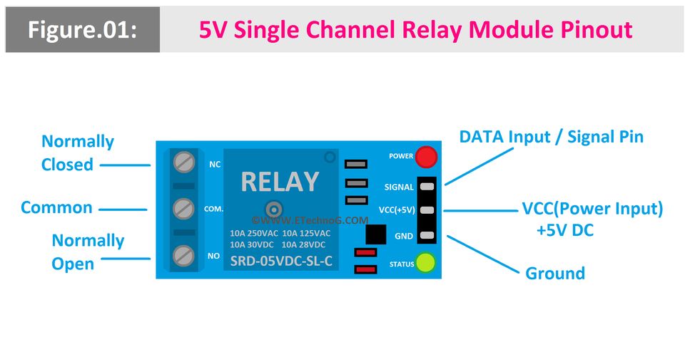
The relay module is here. Image source
I used a 9V battery to control the DC motor. This is the code that I used both for the dc motor as well as the led bulb.
        void setup() {
          pinMode(2, OUTPUT);
        }

        void loop() {
          digitalWrite(2, HIGH);
          delay(1000);
          digitalWrite(2, LOW);
          delay(1000);                 // wait for a second
                          // wait for a second
        }
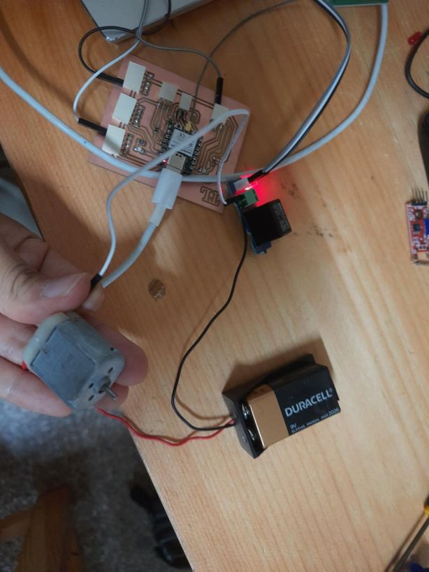
I used bradboard here because I had to use a 1k resistor or else the voltage supplied by the 9V battery would have bombed my poor LED bulb, so to control the excess of it I used a breadboard.
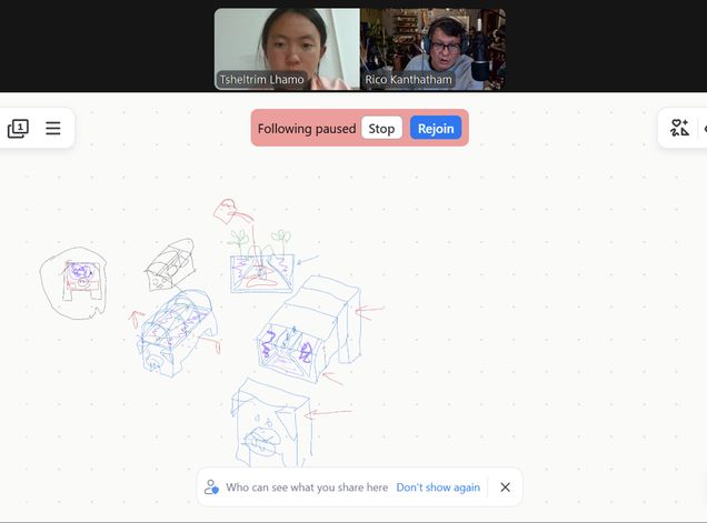
This week mostly, I explored the mechanisms behind output devices and worked with modules such as i2c. Then I had a session with my regional instructor sir Rico and clarified my doubts regarding the model for my final project. This was a briefing where I presented my model and then he suggested useful feedbacks that I will use to further enhance my design.
Key Modifications of my design for now
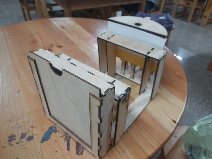
- The unique feature of my design will be that it will be divided into 3 modules-the electronics box, the plant placement box and the water reservoir so that I can scale up my project in the possible.
- The dimensions will be 20 cm by 40 cm by 30 cm.
- The face of the pig will be serve as the electronic box and it willbe able to open and close by sliding it. It will be laser printed and its face features will be engraved.
- There will be a plant placed in the middle module and the moisture sensor and dht22 will be placed inside it
- sThe last module will serve as the water reservoir. That water will be pumped to the middle module with relay passing through a pipe for which a hole has been placed already.
Output Devices-Week13
Networking and Communications-Week11
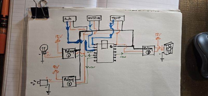
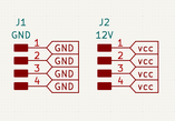
I sent a diagram for my electrical connections for the week and then Sir Rico gave me useful suggestions and advices. He told me that I had connected the relay in the wrong way.
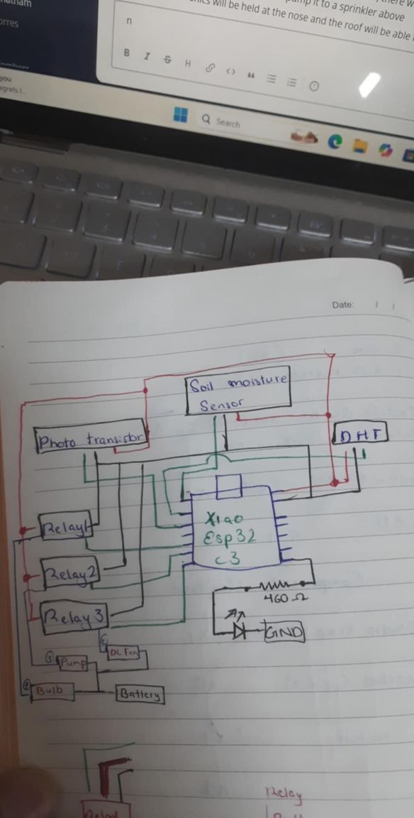
These were his explanations : "The wires from the MCU will be VCC, GND and Signal...to the Relay. From the Relay...there will be a wire in from a power source (+) and a wire out to the device (Motor, Pump, LED) that is also the + wire. The GND wire goes from power source directly to the device."
"basically...the + wire from the power source is 'interrupted' by the relay (switch). the microcontroller sends an ON or OFF signal via the signal wire to allow the 'interruption' to connect or disconnect. The VCC and GND wire to the Relay is to power the Relay module"
He sent me these 2 pictures so I could vidualize and understand better too
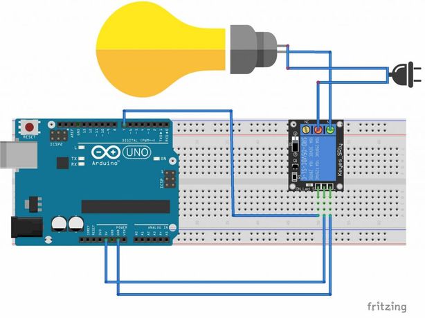
Then he sent me a refined diagram for my electrical components which has helped my understand about the connections better. Thank you Rico san!!!
Molding and Casting- Week 13
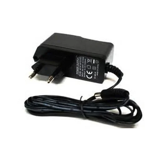
This week, I finalized the power supply for my project. The system will consist of an AC mains supply, stepped down and regulated to provide 9V for high-power components and 5V via a USB interface for the microcontroller. To achieve the required voltage levels, I will integrate two DC-DC buck converters for efficient step-down voltage regulation.
Rico san send me some videos to help me learn about power supply and learn and decide on it.
- How Buck, Boost & Buck-Boost DC-DC Converters Work
- The Most Versatile Voltage Converter you never heard of! The (S)EPIC Converter
- Power For Your Electronics Projects - Voltage Regulators and Converters
- Power ANY Arduino Project - The Ultimate Guide
- Everything You Need to Know about MOSFETs
Then I discussed and finalized my components with my local instructor, Mr.Anith Ghalley.
Applications and Interfaces -Week14
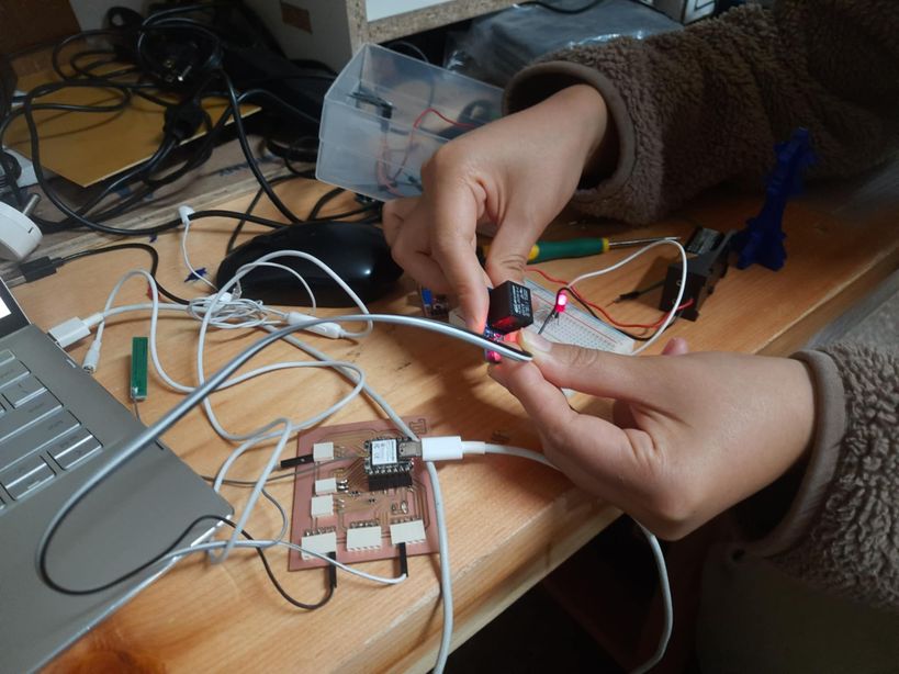
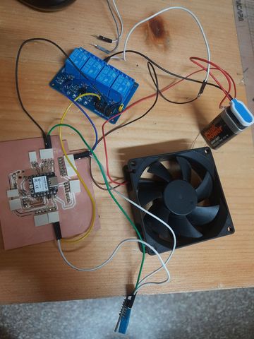
This week, I focused on testing and ensuring that the components functioned correctly. I worked with a 4-channel relay module connected to a DHT sensor. The setup was programmed so that when the DHT sensor detected a temperature above 30°C, it would trigger the relay to turn on a fan. To simulate this condition, I used the warmth of my hands to raise the temperature near the sensor—and it worked perfectly!
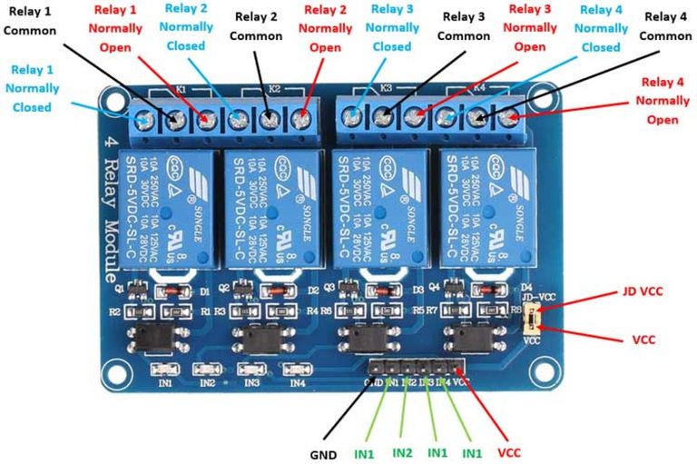
I used the PCB that I made during the Electronics production week , a 4 channel relay, a 9V battery, a 5V dc fan and then some jumper wires.
Connecting the relay to the fan and the power supply and the PCB!
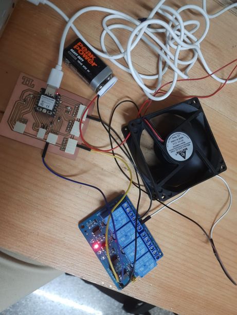
Connecting the dht to the already connected relay
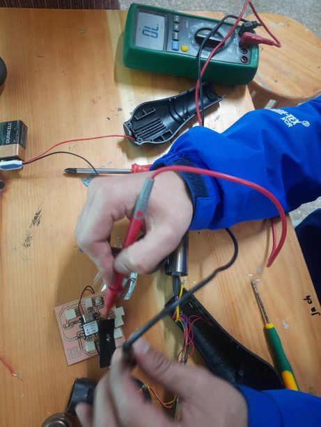
The codes that were uploaded kept on giving issues, so I used a multimetre and BINGO- realized there were some short circuits in my board. So then I remade and remilled a generic board this time and when I tested it with it, it worked fine!! Whoo! That debugging and troubleshooting process was very tiresome. I even tried booting my Xiao several times and even changed my code a lot of times. However the problem lied with my board.
This video showcases the successful test of my program in action. Initially, the fan remained off as the temperature was below 30°C. However, after applying heat to the DHT sensor using my hands—triggering heat transfer—the sensor detected a rise in temperature above 30°C. In response, it sent signals to the Xiao ESP32-C3, which then activated the relay, turning the fan on.
Initially the serial monitor displayed that DHT has failed to sense; it was because the wires were a little lose but then i plugged it properly.
System Integration!
Water Reservoir
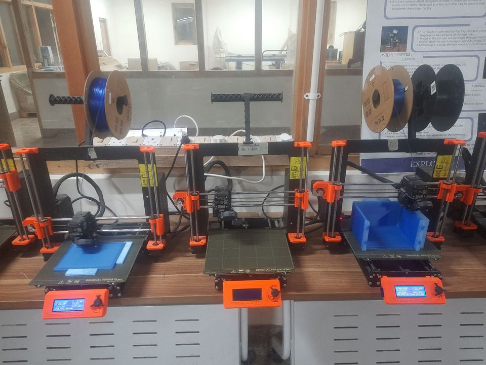
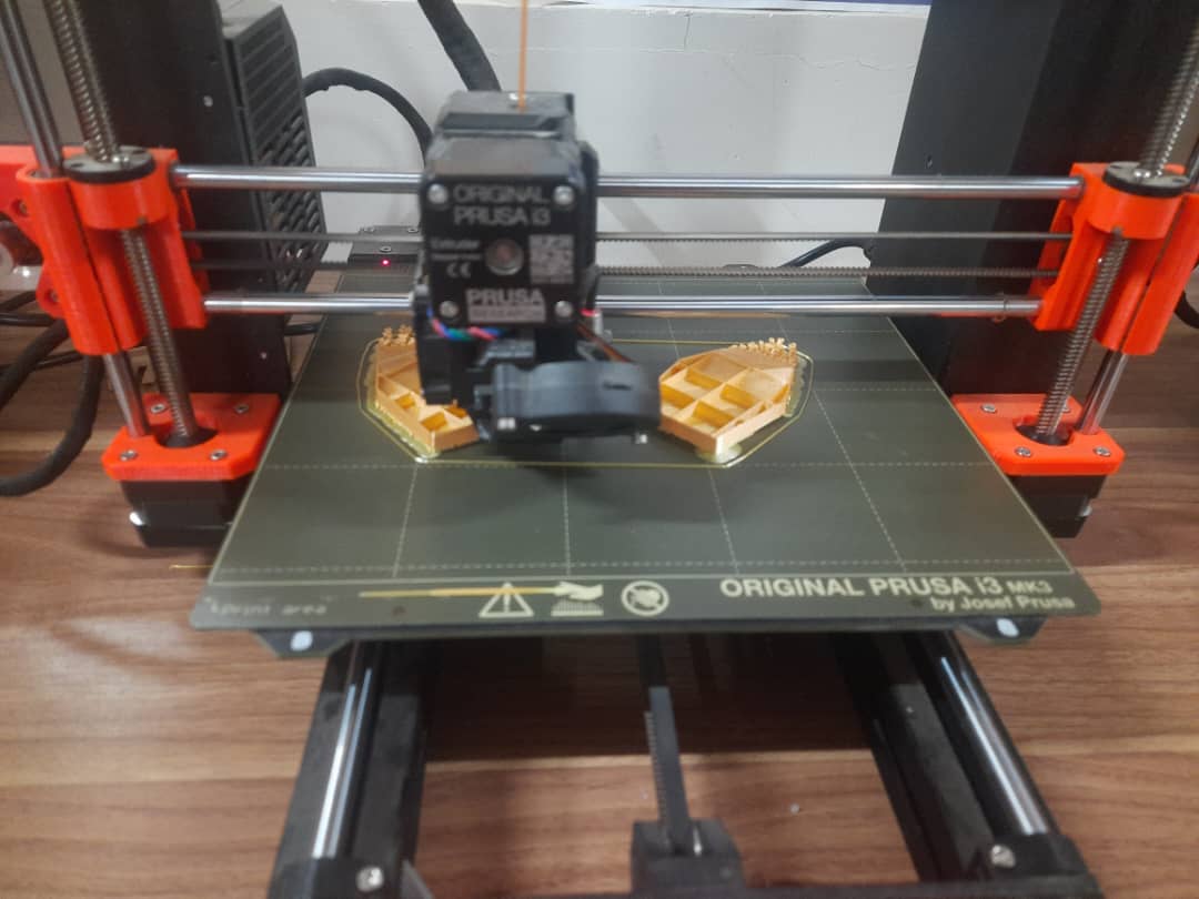
While printing the water reservoir, I modified the base design, increasing its thickness to 8mm to increase its strength. I also changed the print settings as:
- Used the tallest layer height of 0.28mm for faster printing.
- Increased the perimeter walls to 3 for added durability.
- Set the infill density to 15% to balance strength and material usage.
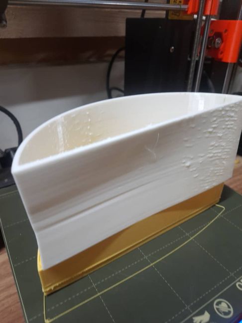
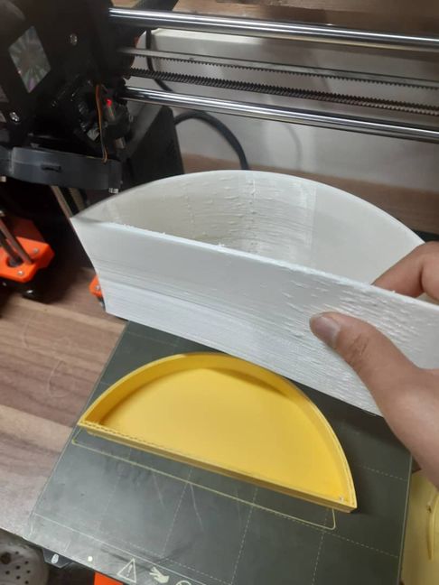
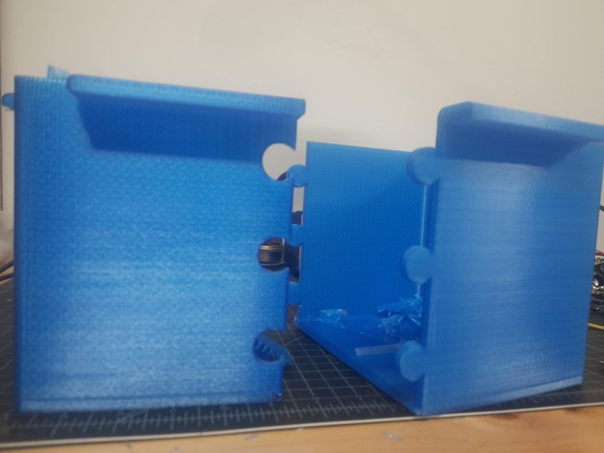
However, midway through printing, the filament ran out. We tried to find the same type but couldn’t, so we switched to a white filament. Unfortunately, it turned out to be TPU which was different from PLA(the yellow filament we used earlier), which caused issues:
- The print quality was affected due to material differences.
- The joint design failed, resulting in separate pieces instead of a cohesive structure.
Waiting for 14 hours for such undesired results was truly a memorable experience but I learned that all filaments werent of the same type and that PLA (Polylactic Acid) and TPU (Thermoplastic Polyurethane) have vastly different properties. PLA is rigid, easy to print, and great for structural parts, while TPU is flexible, elastic, and requires specialized settings for printing.
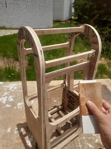
HEROSHOT
Laser cutting and 3d printing took hella lot of time(14 hours for my water reservoir). Though laser cutting took fairly less time as compared however once the pressfit were together, they did not hold up as tightly as I would have liked, so I had to glue it but now I plan on 3d printing corner connectors to connect them instead. And i also plan on using CNC for the middle module to increase it stability.
I was so glad to have the wildcard week because I was able to make meaningful progress with my final project and this made me super glad!
I also re-printed the water resevoir which did not go well last week. and it turned out great.
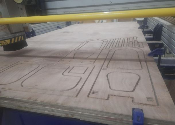
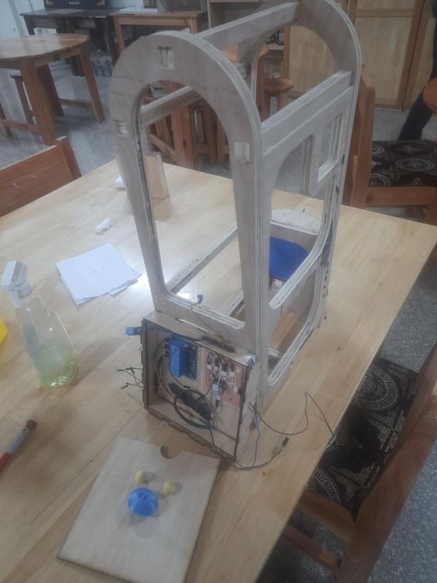
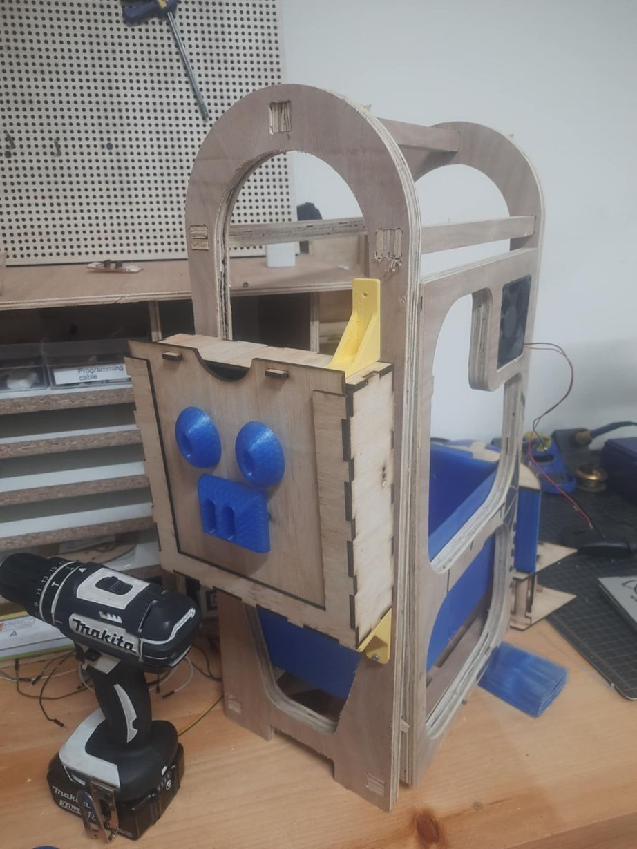
I also designed the 2nd iteration of my design(the middle module) as I will be using the same design as last week for my final project. I fabricated my design using CNC and then attached it using corner connectors that I made last week. I have added a door that will use hinges and locks to be secured for the greenhouse and a specific postition for the fan too.
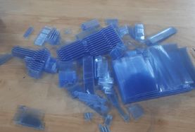
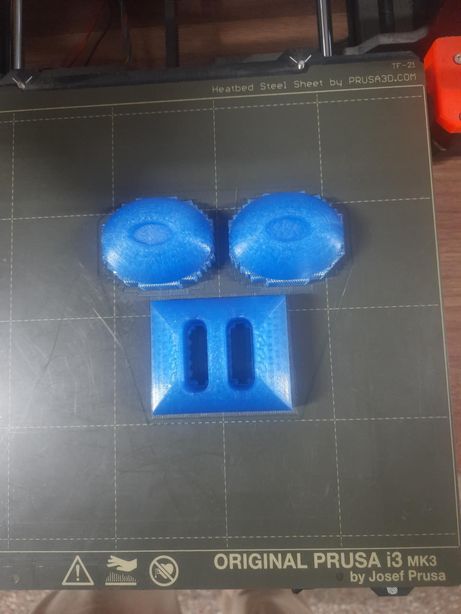
I decided to 3d print my pot for the greenhouse and I sought my instructor Sir Anith's help and was able to create a pot that can slide over like a jigsaw puzzle so that it is not too large for a 3d printer. I will proceed with the printing next week.
I used 2 3d printers to print my design for the flower pot which took approximately 1 day and 12 hours. As mentioned earlier, this pot is a like a jigsaw puzzle that will fit perfectly.
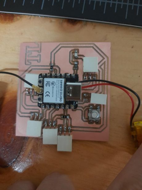
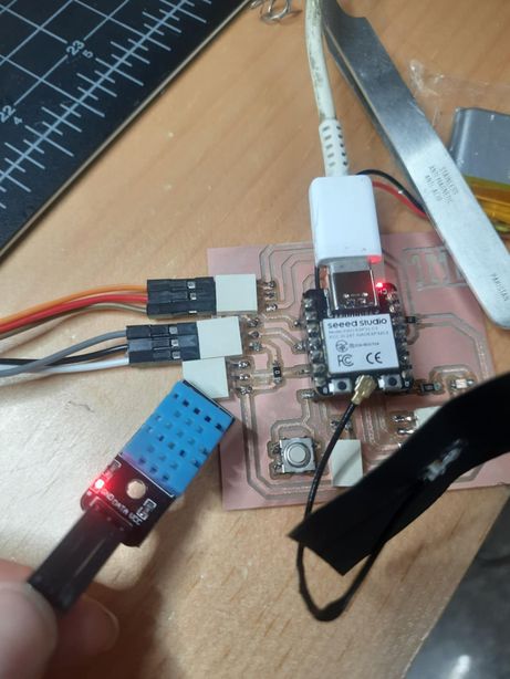
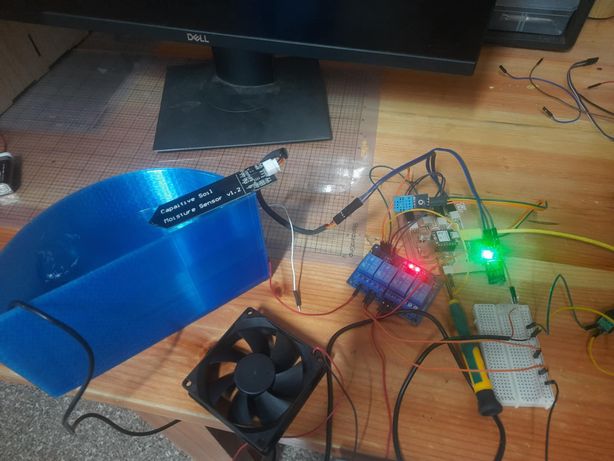
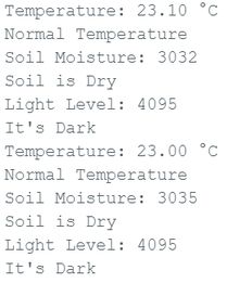
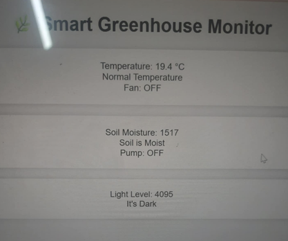
With the help of AI, I generated a code to display all of the inputs of the sensors and tested it just to check the readings. I shone a flashlight at the ldr but then the serial printer said "it is dark", so i just changed it to "it is bright". Otherwise, the code functioned perfectly well. When I dipped the sensor in the water, it displayed correct readings which is the same case for the dht11 sensor. This is an image before connecting all of the wires and programming
_result.jpg)
#include "DHT.h"

// === Pin Definitions ===
#define DHTPIN 3               // DHT11 signal pin
#define DHTTYPE DHT11          // Using DHT11

#define SOIL_MOISTURE_PIN 2    // Analog input for soil moisture
#define LDR_PIN 4              // Analog input for LDR

// === Thresholds for reference ===
#define TEMP_THRESHOLD 30.0           // °C
const int moistureThreshold = 2000;   // Dry soil value (adjust after testing)
const int lightThreshold = 2000;      // Darkness value (adjust after testing)

DHT dht(DHTPIN, DHTTYPE);

void setup() {
  Serial.begin(115200);
  dht.begin();
}

void loop() {
  // === Temperature Reading ===
  float temperature = dht.readTemperature();
  if (isnan(temperature)) {
    Serial.println("Failed to read from DHT11!");
  } else {
    Serial.print("Temperature: ");
    Serial.print(temperature);
    Serial.println(" °C");

    if (temperature > TEMP_THRESHOLD) {
      Serial.println("High Temperature");
    } else {
      Serial.println("Normal Temperature");
    }
  }

  delay(2000);  // Wait before next sensor read

  // === Soil Moisture Reading ===
  int moistureValue = analogRead(SOIL_MOISTURE_PIN);
  Serial.print("Soil Moisture: ");
  Serial.println(moistureValue);

  if (moistureValue < moistureThreshold) {
    Serial.println("Soil is Moist");
  } else {
    Serial.println("Soil is Dry");
  }

  delay(1000);  // Short delay between modules

  // === Light Level Reading ===
  int lightValue = analogRead(LDR_PIN);
  Serial.print("Light Level: ");
  Serial.println(lightValue);

  if (lightValue < lightThreshold) {
    Serial.println("It's Bright");
  } else {
    Serial.println("It's Dark");
  }

  delay(2000);  // Main loop delay
}
I used PLA to print the water reservoir. While I’m aware that PLA is naturally porous and not ideal for holding water over long periods without leaks, I proceeded with it due to its ease of printing and availability. To reduce the risks, I printed it with increased wall thickness of 2mm and 100% infill for better sealing.
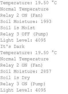
Thus I proceeded to the next spiral where I used the 4 channel relay for corresponding outputs I connected the water pump and when the moisture sensor sensed low readings, it pumped water. With that in place, I connected the fan which i had done in previous weeks and it also worked fine. Now only the LED bulb is left.
#include "DHT.h"

// === Pin Definitions ===
#define DHTPIN 3               // DHT11 signal pin
#define DHTTYPE DHT11          // Using DHT11

#define SOIL_MOISTURE_PIN 2    // Analog input for soil moisture
#define LDR_PIN 4              // Analog input for LDR
#define RELAY3_PIN 6           // Relay 3 (soil moisture control)
#define RELAY2_PIN 7           // Relay 2 (temperature control)

// === Thresholds ===
#define TEMP_THRESHOLD 20.0           // °C
const int moistureThreshold = 2000;   // Dry soil value (adjust after testing)
const int lightThreshold = 2000;      // Darkness value (adjust after testing)

DHT dht(DHTPIN, DHTTYPE);

void setup() {
  Serial.begin(115200);
  dht.begin();

  pinMode(RELAY3_PIN, OUTPUT);
  pinMode(RELAY2_PIN, OUTPUT);

  digitalWrite(RELAY3_PIN, HIGH); // Relay OFF initially (active LOW)
  digitalWrite(RELAY2_PIN, HIGH); // Relay OFF initially (active LOW)
}

void loop() {
  // === Temperature Reading ===
  float temperature = dht.readTemperature();
  if (isnan(temperature)) {
    Serial.println("Failed to read from DHT11!");
  } else {
    Serial.print("Temperature: ");
    Serial.print(temperature);
    Serial.println(" °C");

    if (temperature > TEMP_THRESHOLD) {
      Serial.println("High Temperature");
      digitalWrite(RELAY2_PIN, LOW);  // Fan ON
      Serial.println("Relay 2 ON (Fan)");
    } else {
      Serial.println("Normal Temperature");
      digitalWrite(RELAY2_PIN, LOW); // Fan OFF
      Serial.println("Relay 2 ON (Fan)");
    }
  }

  delay(2000);

  // === Soil Moisture Reading ===
  int moistureValue = analogRead(SOIL_MOISTURE_PIN);
  Serial.print("Soil Moisture: ");
  Serial.println(moistureValue);

  if (moistureValue < moistureThreshold) {
    Serial.println("Soil is Moist");
    digitalWrite(RELAY3_PIN, HIGH);  // Pump OFF
    Serial.println("Relay 3 OFF (Pump)");
  } else {
    Serial.println("Soil is Dry");
    digitalWrite(RELAY3_PIN, LOW);   // Pump ON
    Serial.println("Relay 3 ON (Pump)");
  }

  delay(1000);

  // === Light Level Reading ===
  int lightValue = analogRead(LDR_PIN);
  Serial.print("Light Level: ");
  Serial.println(lightValue);

  if (lightValue < lightThreshold) {
    Serial.println("It's Bright");
  } else {
    Serial.println("It's Dark");
  }

  delay(2000);  // Main loop delay
}
Then I realized that there is no means that will display the rela time data(only in serial monitor), so I created a website using IP address and Wifi.
However my instructor advised me to display the real time data using OLED instead because for my web to work, it needs a specific IP address without which it would be hard to monitor. So next week I will be working on it.
| Component Name | Specification | Price (Nu.) | Price (USD) | Quantity | Total Cost (Nu.) | Online or Local Market |
|---|---|---|---|---|---|---|
| Soil moisture sensor | Capacitive V2.0 | 54 | 0.65 | 1 | 54 | Available in the lab |
| DHT22 | AM2302 | 121 | 1.46 | 1 | 121 | Available in the lab |
| LDR | Photoresistor | 149 | 1.80 | 1 | 149 | Available in the lab |
| 4 channel relay | 5V module | 219 | 2.64 | 1 | 219 | Available in the lab |
| Water pump | Submersible | 398 | 4.80 | 1 | 398 | Available in the lab |
| Xiao ESP32 C3 | Wi-Fi + BLE | 471 | 5.67 | 1 | 471 | Available in the lab |
| LED bulb | 12V DC | 159 | 1.91 | 1 | 159 | Available in the lab |
| 240V to 12V converter | Step down | 190 | 2.29 | 1 | 190 | Available in the lab |
| USB Wall charger | 5V 1A | 190 | 2.29 | 1 | 190 | Available in the lab |
| Fan | 3-inch DC | — | — | 1 | 0 | Available in the lab |
| Plastic Polyethylene | 2m x 2m | 100 | 1.20 | 1 | 100 | Available in the lab |
| PLA filament for 3D printing | Deep Blue, 2 kg | 849 | 9.95 | 2 | 1698 | Available in the lab |
| 4mm wood | Laser cutting (30cm x 20cm) | 40 | 0.47 | 1 | 40 | Available in the lab |
| 18mm wood | CNC (2400mm x 1200mm) | 1200 | 14.06 | 1 | 1200 | Available in the lab |
| Vinyl sticker | Yellow Glossy Wrap | 249 | 2.92 | 1 | 249 | Available in the lab |
| Total (Nu.) | 5637 | (All Available in the Lab) | ||||
| Total (USD) | $66.41 USD | |||||


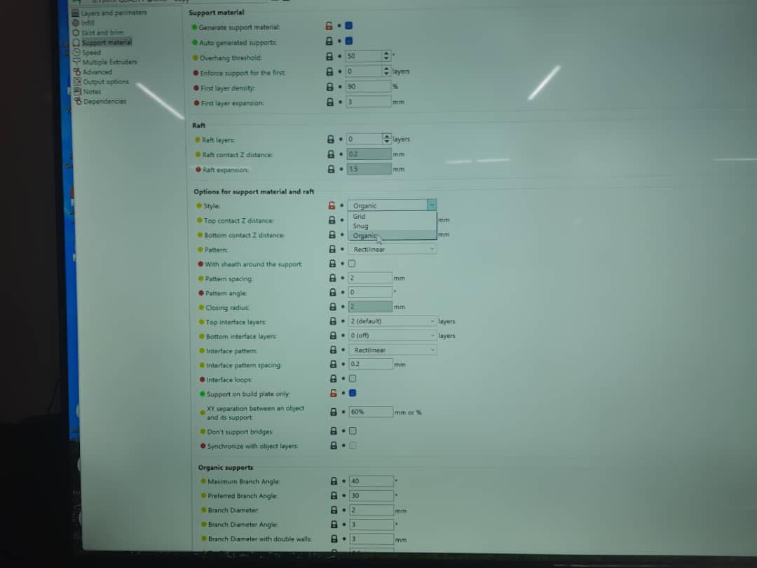
To 3d print, we used organic as our support material because it helps reduce a lot of time and infill from being wasted.
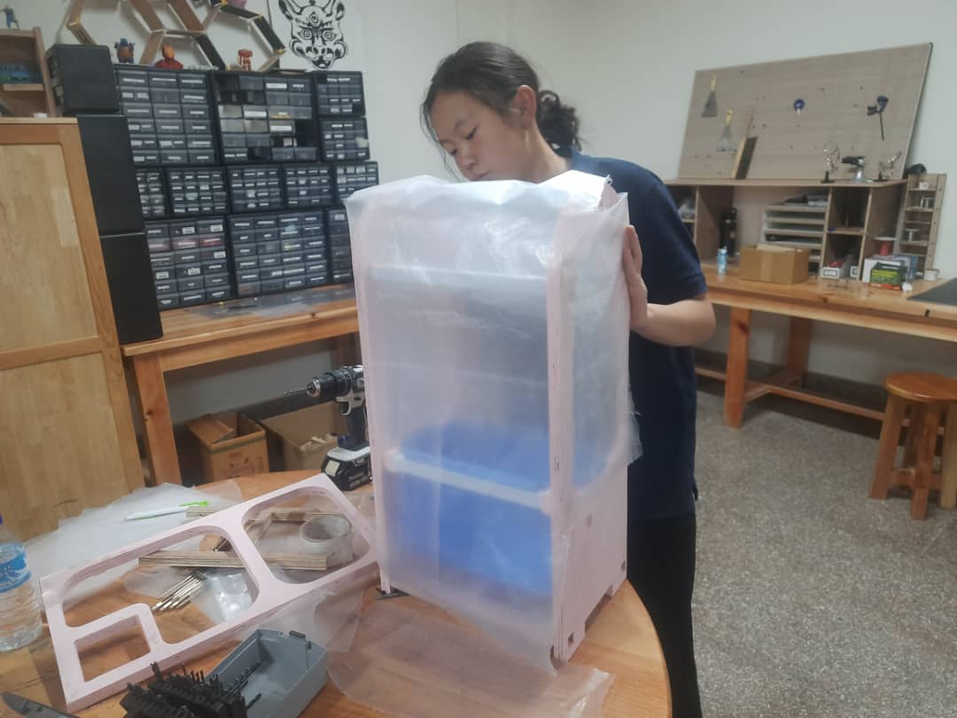
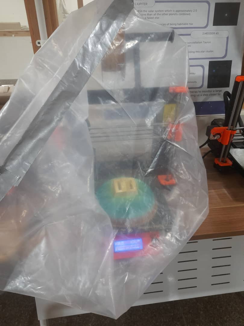
However we realized that due to temperature fluctuations at the lab, the prints were becoming ruined so we insulated it with plastic originally used for my project.
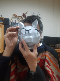
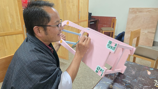
After printing the 1st design, I realized that it was smaller than what I initially planned on so I reprinted it with the head as a different part and the ears differently connecting them with hot glue gun in the end. This is an image of Sir Rico holding the pigs head.
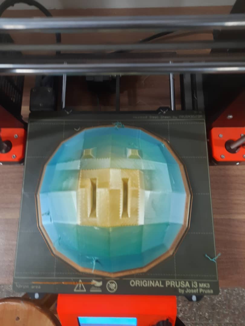
My 2nd print that turned out pretty decent
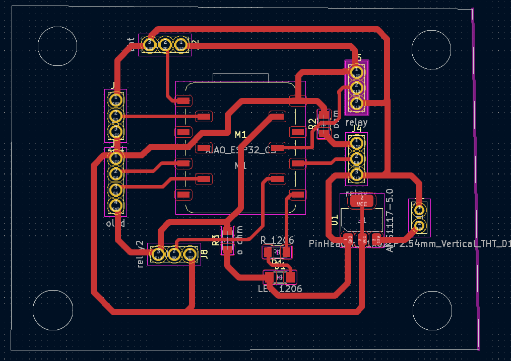
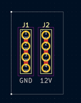
This is the custom board that I created. The main board for the MCU with a 5V regulator and functionalities control, one board for the power supply which will have a supply of 12 V from the adaptor and then it will take to the main board, the fan, the water pump and 1 pinout for the main supply coming from the 12 V adaptor via a connector.


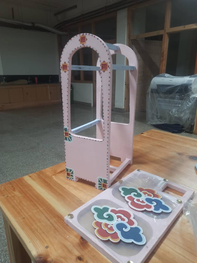
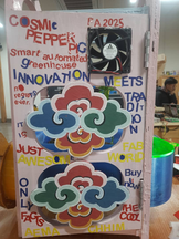
Huge thank you goes to Lopen Thukten who helped me paint it so that technology meets tradition and make it aesthetically appealing.
To add a sense of my own aesthetics, i decided to do a grafitti of vinyl stickers and this is how it turned out!
Afterwards I braided the wires as a part of system integration making sure that they were hidden very well.I screwed the pcb and the relay to the head. There were braided together and then passed through the CNCed part and then taken to their respective connections underneath the pot. I also used zip ties to make sure they are grouped in the cleanest way possible.

This is the code that I generated with the help of AI-ChatGPT so the credit goes to AI
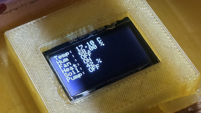
#include "DHT.h" #include#include #include #define DHTPIN 2 #define DHTTYPE DHT11 #define SOIL_PIN 3 #define PUMP_RELAY_PIN 8 // Water pump #define FAN_RELAY_PIN 10 // Fan for high temp #define TEMP_HIGH_THRESHOLD 30 // Temp above which fan turns on #define TEMP_LOW_THRESHOLD 20 // Temp below which heater turns on #define SOIL_THRESHOLD_PERCENT 30 // Below this %, water the soil #define SCREEN_WIDTH 128 #define SCREEN_HEIGHT 64 #define OLED_RESET -1 #define I2C_SDA 6 #define I2C_SCL 7 DHT dht(DHTPIN, DHTTYPE); TwoWire I2C_OLED = TwoWire(0); Adafruit_SSD1306 display(SCREEN_WIDTH, SCREEN_HEIGHT, &I2C_OLED, OLED_RESET); void setup() { Serial.begin(115200); dht.begin(); analogReadResolution(12); pinMode(PUMP_RELAY_PIN, OUTPUT); pinMode(FAN_RELAY_PIN, OUTPUT); digitalWrite(PUMP_RELAY_PIN, HIGH); digitalWrite(FAN_RELAY_PIN, HIGH); I2C_OLED.begin(I2C_SDA, I2C_SCL, 100000); if (!display.begin(SSD1306_SWITCHCAPVCC, 0x3C)) { Serial.println(F("SSD1306 allocation failed")); while (true); } display.clearDisplay(); display.setTextSize(1); display.setTextColor(SSD1306_WHITE); display.setCursor(0, 0); display.println("Initializing..."); display.display(); delay(1000); } void loop() { float temp = dht.readTemperature(); float hum = dht.readHumidity(); int soilRaw = analogRead(SOIL_PIN); int soilPercent = map(soilRaw, 4095, 0, 0, 100); // === Temperature control === if (!isnan(temp)) { if (temp >= TEMP_HIGH_THRESHOLD) { digitalWrite(FAN_RELAY_PIN, LOW); } else if (temp < TEMP_LOW_THRESHOLD) { digitalWrite(FAN_RELAY_PIN, HIGH); } else { digitalWrite(FAN_RELAY_PIN, HIGH); } } // === Soil Moisture control === if (soilPercent < SOIL_THRESHOLD_PERCENT) { digitalWrite(PUMP_RELAY_PIN, LOW); } else { digitalWrite(PUMP_RELAY_PIN, HIGH); } // === OLED Display === display.clearDisplay(); display.setCursor(0, 0); if (isnan(temp) || isnan(hum)) { display.println("DHT Error!"); } else { display.print("Temp: "); display.print(temp); display.println(" C"); display.print("Hum : "); display.print(hum); display.println(" %"); display.print("Fan : "); display.println(temp >= TEMP_HIGH_THRESHOLD ? "ON" : "OFF"); display.print("Heat: "); display.println(temp < TEMP_LOW_THRESHOLD ? "ON" : "OFF"); } display.print("Soil: "); display.print(soilPercent); display.println(" %"); display.print("Pump: "); display.println(soilPercent < SOIL_THRESHOLD_PERCENT ? "ON" : "OFF"); display.display(); // === Serial Monitor Output === Serial.print("Temp: "); Serial.print(temp); Serial.print(" C, "); Serial.print("Humidity: "); Serial.print(hum); Serial.print(" %, "); Serial.print("Soil: "); Serial.print(soilPercent); Serial.println(" %"); delay(2000); }
HEROSHOT

This is a video that showcases the 1st function of my project which is automatic irrigation as water pump is activated when soil moisture is below a certain threshold. I supplied heat to the dht11 using my hands.
This is the command i used to compress this video: ffmpeg -i function1.mp4 -vcodec libx264 -crf 28 -an function1_compressed.mp4
This video demonstrates the second function of my project: automatic temperature regulation and improved air ventilation. The DC fan activates when the temperature exceeds a predefined threshold.
This is the command i used to compress this video: ffmpeg -i function2.mp4 -vcodec libx264 -crf 28 -an function2_compressed.mp4
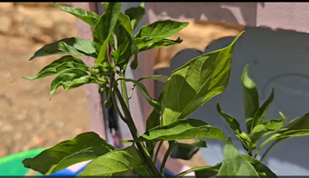
A very healthy and happy pepper plant in it.
Files
You can access the files here
Boards that i used-power and my main MCU
All of the designs for my final project