
Table of Contents
- Applications and Implications:
- Propose a final project masterpiece that integrates the range of units covered.
- 2D and 3D design
- Additive and subtractive fabrication processes
- Electronics design and production
- System integration and packaging.
- Where possible, you should make rather than buy the parts of your project. Projects can be separate or joint, but need to show individual mastery of the skills, and be independently operable.
- Project Development
- Complete your final project tracking your progress.
Applications and Implications:
Project Information: The Cosmic Pepper Pig
-
What will it do?
- The Cosmic Pepper Pig is a smart automated system designed to optimize chili growth in cold mountainous regions.
- It monitors temperature, humidity, soil moisture, and light, and controls internal conditions via fans, heaters, LEDs, and water pumps.
- It records environmental data and logs it to a Google Sheet for analysis.
- What does it do?
The Cosmic Pepper Pig's project is a prototype for a smart automated system designed to cultivate pepper in cold mountainous climates. It regulates temperature, humidity, and soil moisture using sensors and automation, ensuring optimal conditions for plant growth. - Who’s done what beforehand?
Mr. Ari Vuokila and Ms. Loise Kimwe completed similar projects in Fab Academy. IoT greenhouse automation. - Though there are a lot of projects done beforehand, the unique point of my project is the animal figure of it making it look fun and interesting.
-
What will I design?
- 3D model of the system frame using Fusion 360.
- 3D model of the head of the pig using Blender
- Custom PCB for sensor and actuator control.
- 3D model of water reservoir in fusion 360 and its lid.
- Custom PCB for sensor and actuator control.
-
What materials and components will be used?
- PLA filament for 3D printing the water reservoir, the pot and the face of the pig.
- 18 mm wood to CNC the structure of the greenhouse[middle module].
- Xiao ESP32 C3 as the microcontroller.
- dht11 and capacitive soil moisture sensors.
- DC fan, oled, water pump and a 4 channel relay.
-
Where will they come from?
- PLA, 4 mm wood and 18mm wood, and basic components from Fab Lab inventory.
- Advanced sensors and pumps ordered from Robu.in or Amazon or from local stores.
-
How much will they cost?
Component Name Specification Price (Nu.) Price (USD) Quantity Total Cost (Nu.) Online or Local Market Soil moisture sensor Capacitive V2.0 54 0.65 1 54 Available in the lab DHT22 AM2302 121 1.46 1 121 Available in the lab LDR Photoresistor 149 1.80 1 149 Available in the lab 4 channel relay 5V module 219 2.64 1 219 Available in the lab Water pump Submersible 398 4.80 1 398 Available in the lab Xiao ESP32 C3 Wi-Fi + BLE 471 5.67 1 471 Available in the lab LED bulb 12V DC 159 1.91 1 159 Available in the lab 240V to 12V converter Step down 190 2.29 1 190 Available in the lab USB Wall charger 5V 1A 190 2.29 1 190 Available in the lab Fan 3-inch DC — — 1 0 Available in the lab Plastic Polyethylene 2m x 2m 100 1.20 1 100 Available in the lab PLA filament for 3D printing Deep Blue, 1 kg 849 9.95 1 849 Available in the lab 4mm wood Laser cutting (30cm x 20cm) 40 0.47 1 40 Available in the lab 18mm wood CNC (2400mm x 1200mm) 1200 14.06 1 1200 Available in the lab Total (Nu.) 4136 (All Available in the Lab) Total (USD) $48.54 USD -
What parts and systems will be made?
- Custom system structure and enclosure.
- PCB development board for sensors and relays.
- Holders and mounts for components.
- Integration of power, control, and monitoring systems.
- How will I collect, communicate, and store sensor data effectively?
- Which platform or tools will I use for real-time data visualization and storage (e.g., Google Sheets, cloud services)?
- What is my project timeline and am I on track to complete each milestone?
- What style do I want to present my final project through video or demonstration?
-
What processes will be used?
- 3D design in Fusion 360.
- Additive manufacturing via 3D printing.
- Subtractive fabrication via laser cutting and CNC.
- PCB design and milling using KiCad and Mods.
- Programming in Arduino IDE for embedded systems.
-
What questions need to be answered?
- Data Collection & Communication: How will I effectively collect, communicate, and store the sensor data.
- Timeline & Milestones: Am I on track to complete each milestone.
- Final Presentation: How do I plan to present my final project (video and poster).
-
How will it be evaluated?
How will it be evaluated?
To me, a successful project is one that brings together everything I’ve learned and actually works. It should be able to:
- Minimum Functionalities: It should at least be able to monitor temperature, humidity, and soil moisture, and respond by turning on a fan, or a water pump automatically.
- System Uptime: It should run continuously without major crashes for at least 48 hours, proving it’s stable for real usage.
- Measurement Precision: Sensor readings should stay within ±5% of actual values when tested against reliable references.
- Design Integration: The enclosure should clearly reflect my 2D and 3D design skills, and all components should fit together neatly and securely.
- Electronics and Programming: My custom PCB should function correctly, with well-soldered connections and clean, readable code that reliably controls the system.
- System Integration: All parts—hardware, sensors, code, and design—should work together smoothly, without me having to fix things constantly for it to run. The wires should also be braided and hidden properly.
- Documentation & Presentation: My weekly documentation and final project page should clearly show my process, learning, and outcomes. I want someone who reads it to fully understand what I did, how I did it, and what worked or didn’t.
I believe that if I can meet these criteria, then I’ve not only built a working system but also proven my understanding of design, fabrication, electronics, programming, and system thinking—all at once.
-
What tasks have been completed?
- Mechanical Design & Fabrication:
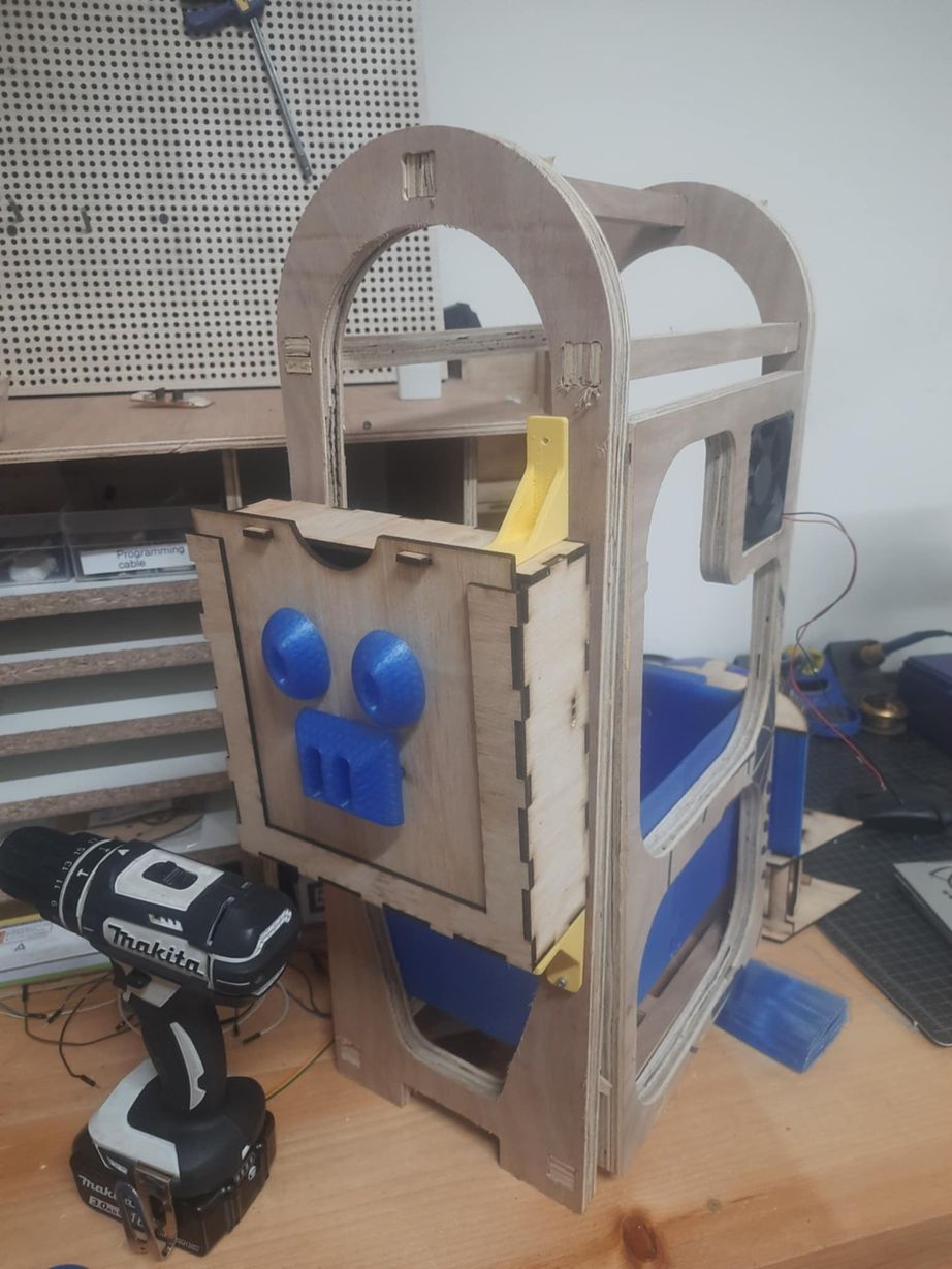
- Designed and laser-cut the 2nd iteration of the pig head enclosure (press-fit box) and CNCed the middle module.
- Designed the segmented flower pot in Fusion 360 for modular 3D printing.
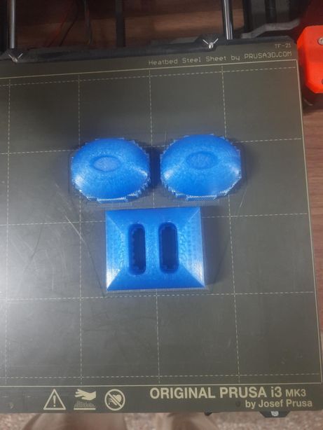
- Successfully 3D printed the water reservoir, multi-part pot, eyes, and nose.
- Assembled the laser-cut head with the 3D printed eyes and nose.
- Electronics & Programming (Initial Stages):
- Developed and tested Arduino code for reading DHT11 (temperature/humidity), soil moisture, and LDR (light) sensors.
- Successfully integrated and tested the water pump, which activates when the soil moisture sensor detects dryness.
- Successfully integrated and tested the fan, which activates based on temperature (though the current logic needs a small adjustment).
- Explored and briefly implemented a web server display for real-time data via IP address.
- Mechanical Design & Fabrication:
-
What tasks remain?
To bring "Cosmic Pepper Pig" to full functionality, these tasks are next on my list:
- Final Electronics Integration:
- Design and mill my custom PCB for all sensor and relay connections.
- Implement the OLED display for local, real-time sensor data visualization, replacing the web display.
- Physical Integration:
- Full assembly of the greenhouse structure, including the water reservoir, its stand, and the door with hinges and locks.
- Neat and secure mounting of all electronic components within the enclosure.
- Integration of the 3D printed pot into the main structure.
- Final Testing & Refinement: Thoroughly test the entire system under various conditions and fine-tune parameters as needed.
- Final Electronics Integration:
-
What has worked? What hasn’t?
- What has worked well:
- My CAD designs for laser cutting and 3D printing came out well. The headand the pot looked exactly how I imagined them with the help of my instructors of course-Mr.Anith Ghalley and Mr.Rico because the fluctuations in temperature around the 3d printer kept on messing the prints, so they helped a lot by placing a plastic on it to insulate the heat.
- The CNC went smoothly. All the pieces printed without any big problems, and I was able to assemble them properly.
- The sensors I used like DHT11, and soil moisture sensor gave accurate readings during my tests, which made me feel confident in the setup.
- I was also able to generate and edit a working code with the help of AI that automatically turned on the fan and water pump based on sensor data. It’s a great feeling when the logic you wrote actually works!
- At first, I used a web server to show sensor values, and it worked well when I accessed it using the IP address.
- What hasn’t worked (or needs more work):
- The IP-based web display worked, but I realized it’s not practical for long-term use because the IP keeps changing. So I decided to use an OLED screen instead for more reliable data display.
What have I learned?
I’ve learned that building a full project like this is more than just connecting wires and writing code. Everything has to come together — from the design of the parts, to choosing the right sensors, to making sure the code runs reliably. I also learned that things don’t always go the way I expect. Sometimes the sensor doesn’t work, or the IP address changes, or the 3D print fails. But I learned to find solutions and move on. It felt really good to fix problems and improve things step by step.
One of the biggest things I realized is how important planning is. When I rushed, I made mistakes. But when I took time to think and test carefully, things worked much better. Also, I got better at debugging code and understanding how different parts of a system talk to each other. I feel more confident now to take on bigger projects in the future.
- What has worked well:
-
What questions need to be resolved?
- Writing the code to display the sensor values clearly and effectively on OLED.
-
What will happen when?
You can refer to my GANTT CHART here
-
What have I learned?
Working on “The Cosmic Pepper Pig” has taught me so many things, not just technically but also in how to think and plan better.
- Designing in parts: Since my 3D printer couldn’t make really big pieces(the pot), I learned how to break my pot design into smaller parts that I could assemble later. This helped me understand modular design better.
- Connecting sensors and outputs: I learned how to use sensors like the soil moisture sensor, and DHT11, and connect them to outputs like a fan or water pump using relays. It made me understand how everything in a system is linked and how important correct wiring and coding are.
- Testing and improving: Not everything worked on the first try. I had to redesign the pot, tweak my code, and even change the way I displayed data (from a web page to an OLED screen). I’ve learned that projects need testing and improvement again and again.
- Fixing problems: I faced some confusing issues, like wrong light readings or the web display not being reliable. I didn’t give up — I searched, asked for help, and tried different ideas until it worked. I feel like I’ve become much better at debugging and solving problems.
- Planning ahead: Making a list of what I needed — components, price, and time — helped me see how much work a full project takes. I’ve started to understand how to manage tasks better and not just jump into building without thinking it through first.
Overall, this project has been a mix of learning, struggling, and small victories. It made me realize how much I enjoy making things — and that learning by doing is the best way for me.
Key Questions to Answer
Project Requirements and Goals
Project Development
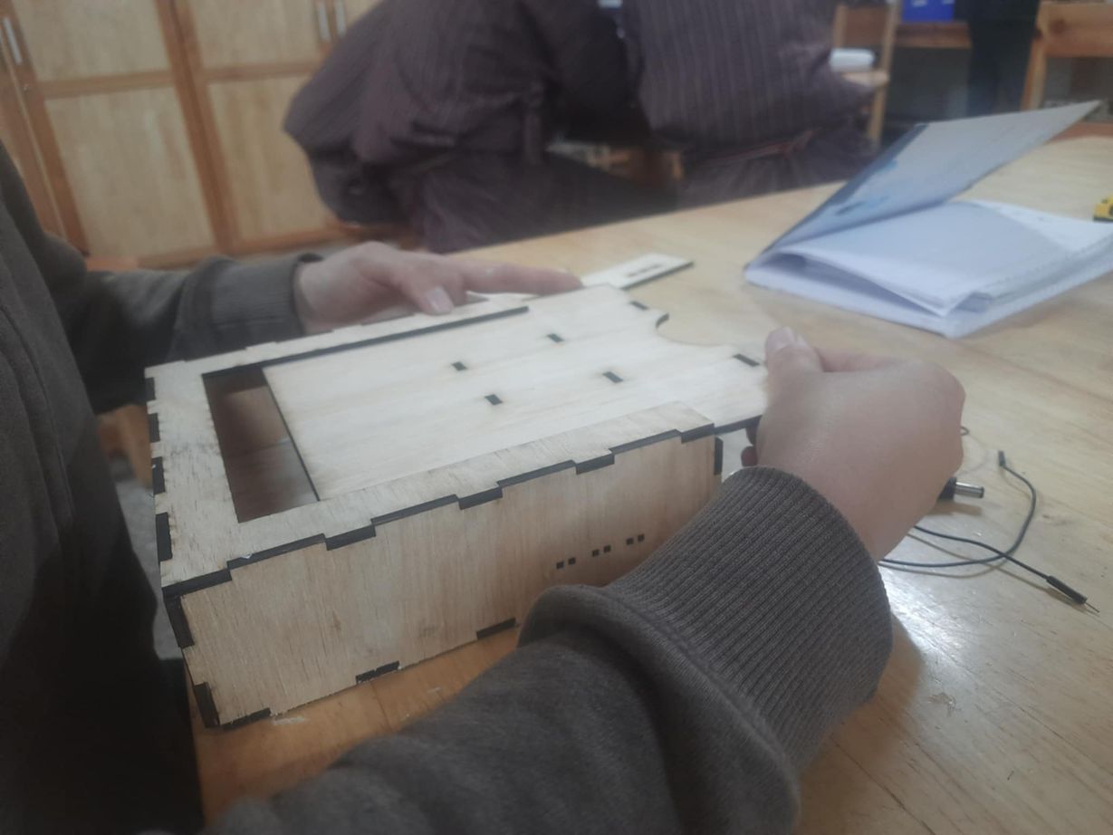
I used the laser cutter to fabricate the 2nd iteration of my design(the head-pressfit box) for the electronics with slots to put in the 3d printed eyes and nose.
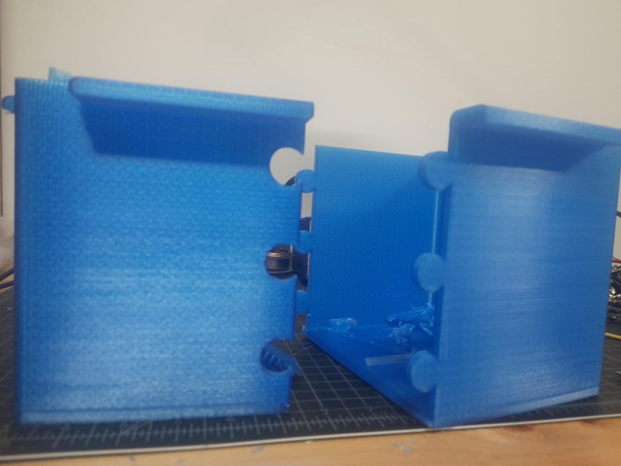
I decided to 3d print my pot for the greenhouse and I sought my instructor Sir Anith's help and was able to create a pot that can slide over like a jigsaw puzzle so that it is not too large for a 3d printer. I will proceed with the printing next week.
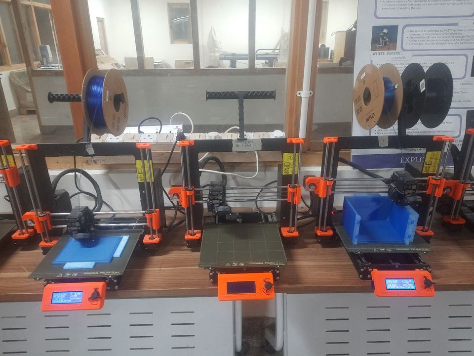
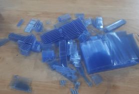
I used 2 3d printers to print my design for the flower pot which took approximately 36 hours each h As mentioned earlier, this pot is a like a jigsaw puzzle that will fit perfectly.
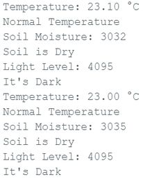
With the help of AI, I generated a code to display all of the inputs of the sensors and tested it just to check the readings. I shone a flashlight at the ldr but then the serial printer said "it is dark", so i just changed it to "it is bright". Otherwise, the code functioned perfectly well. When I dipped the sensor in the water, it displayed correct readings which is the same case for the dht11 sensor. This is an image before connecting all of the wires and programming
_result.jpg)
#include "DHT.h"

// === Pin Definitions ===
#define DHTPIN 3               // DHT11 signal pin
#define DHTTYPE DHT11          // Using DHT11

#define SOIL_MOISTURE_PIN 2    // Analog input for soil moisture
#define LDR_PIN 4              // Analog input for LDR

// === Thresholds for reference ===
#define TEMP_THRESHOLD 30.0           // °C
const int moistureThreshold = 2000;   // Dry soil value (adjust after testing)
const int lightThreshold = 2000;      // Darkness value (adjust after testing)

DHT dht(DHTPIN, DHTTYPE);

void setup() {
  Serial.begin(115200);
  dht.begin();
}

void loop() {
  // === Temperature Reading ===
  float temperature = dht.readTemperature();
  if (isnan(temperature)) {
    Serial.println("Failed to read from DHT11!");
  } else {
    Serial.print("Temperature: ");
    Serial.print(temperature);
    Serial.println(" °C");

    if (temperature > TEMP_THRESHOLD) {
      Serial.println("High Temperature");
    } else {
      Serial.println("Normal Temperature");
    }
  }

  delay(2000);  // Wait before next sensor read

  // === Soil Moisture Reading ===
  int moistureValue = analogRead(SOIL_MOISTURE_PIN);
  Serial.print("Soil Moisture: ");
  Serial.println(moistureValue);

  if (moistureValue < moistureThreshold) {
    Serial.println("Soil is Moist");
  } else {
    Serial.println("Soil is Dry");
  }

  delay(1000);  // Short delay between modules

  // === Light Level Reading ===
  int lightValue = analogRead(LDR_PIN);
  Serial.print("Light Level: ");
  Serial.println(lightValue);

  if (lightValue < lightThreshold) {
    Serial.println("It's Bright");
  } else {
    Serial.println("It's Dark");
  }

  delay(2000);  // Main loop delay
}
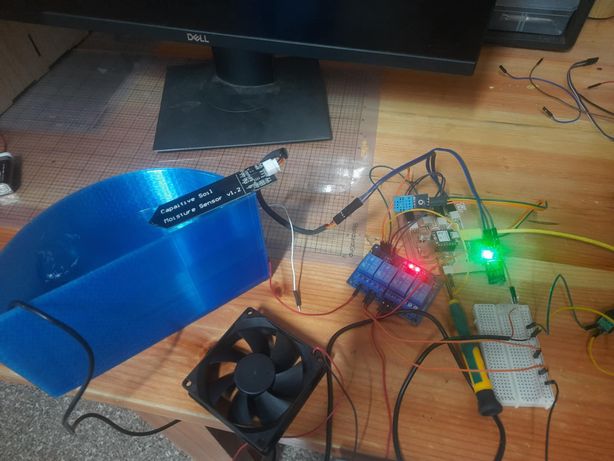
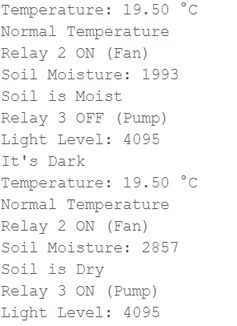
Thus I proceeded to the next spiral where I used the 4 channel relay for corresponding outputs I connected the water pump and when the moisture sensor sensed low readings, it pumped water. With that in place, I connected the fan which i had done in previous weeks and it also worked fine. Now only the LED bulb is left.
#include "DHT.h"

// === Pin Definitions ===
#define DHTPIN 3               // DHT11 signal pin
#define DHTTYPE DHT11          // Using DHT11

#define SOIL_MOISTURE_PIN 2    // Analog input for soil moisture
#define LDR_PIN 4              // Analog input for LDR
#define RELAY3_PIN 6           // Relay 3 (soil moisture control)
#define RELAY2_PIN 7           // Relay 2 (temperature control)

// === Thresholds ===
#define TEMP_THRESHOLD 20.0           // °C
const int moistureThreshold = 2000;   // Dry soil value (adjust after testing)
const int lightThreshold = 2000;      // Darkness value (adjust after testing)

DHT dht(DHTPIN, DHTTYPE);

void setup() {
  Serial.begin(115200);
  dht.begin();

  pinMode(RELAY3_PIN, OUTPUT);
  pinMode(RELAY2_PIN, OUTPUT);

  digitalWrite(RELAY3_PIN, HIGH); // Relay OFF initially (active LOW)
  digitalWrite(RELAY2_PIN, HIGH); // Relay OFF initially (active LOW)
}

void loop() {
  // === Temperature Reading ===
  float temperature = dht.readTemperature();
  if (isnan(temperature)) {
    Serial.println("Failed to read from DHT11!");
  } else {
    Serial.print("Temperature: ");
    Serial.print(temperature);
    Serial.println(" °C");

    if (temperature > TEMP_THRESHOLD) {
      Serial.println("High Temperature");
      digitalWrite(RELAY2_PIN, LOW);  // Fan ON
      Serial.println("Relay 2 ON (Fan)");
    } else {
      Serial.println("Normal Temperature");
      digitalWrite(RELAY2_PIN, LOW); // Fan OFF
      Serial.println("Relay 2 ON (Fan)");
    }
  }

  delay(2000);

  // === Soil Moisture Reading ===
  int moistureValue = analogRead(SOIL_MOISTURE_PIN);
  Serial.print("Soil Moisture: ");
  Serial.println(moistureValue);

  if (moistureValue < moistureThreshold) {
    Serial.println("Soil is Moist");
    digitalWrite(RELAY3_PIN, HIGH);  // Pump OFF
    Serial.println("Relay 3 OFF (Pump)");
  } else {
    Serial.println("Soil is Dry");
    digitalWrite(RELAY3_PIN, LOW);   // Pump ON
    Serial.println("Relay 3 ON (Pump)");
  }

  delay(1000);

  // === Light Level Reading ===
  int lightValue = analogRead(LDR_PIN);
  Serial.print("Light Level: ");
  Serial.println(lightValue);

  if (lightValue < lightThreshold) {
    Serial.println("It's Bright");
  } else {
    Serial.println("It's Dark");
  }

  delay(2000);  // Main loop delay
}
Then I realized that there is no means that will display the rela time data(only in serial monitor), so I created a website using IP address and Wifi.
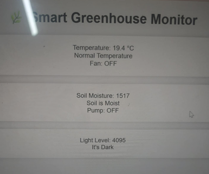
However my instructor advised me to display the real time data using OLED instead because for my web to work, it needs a specific IP address without which it would be hard to monitor. So next week I will be working on it.
Files
You can access the files here
f3d files for the 2nd iteration of the enclosure design.