VoxPlotter: The Voice-Controlled Pen Plotter
This project is licensed under a Creative Commons Attribution-NonCommercial 4.0 International License (CC BY-NC 4.0). This means you are free to share and adapt the work, as long as you give appropriate credit. Do not use it for commercial purposes. Indicate if changes were made. For any reuse or distribution, you must make the license terms clear to others.
Presentation Slide
Presentation Video
For just my hero shot, click this link
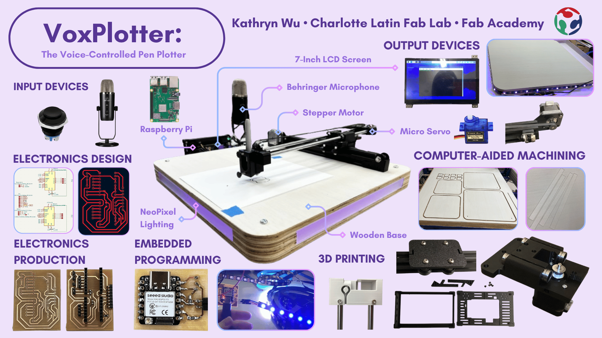
Final Project Overview
The VoxPlotter is a 3-axis, voice-activated pen plotter that draws curated G-code designs in response to spoken commands. A button press triggers voice recording through a microphone on a Raspberry Pi 4, which transcribes the audio to text using faster-whisper, matches it to a stored G-code file that drives the stepper motors and pen-lift servo. I designed and fabricated the 3D-printed pen mechanism and mounts, a custom motorshield PCB (debugged through several iterations), a separate LED-control board, and a milled plywood base with frosted acrylic panels and integrated lighting. The full build draws on nearly every skill from the term (CAD, laser cutting, embedded programming, electronics design and production, CNC machining, and system integration) and runs the complete pipeline end-to-end, from voice command to a finished drawing.
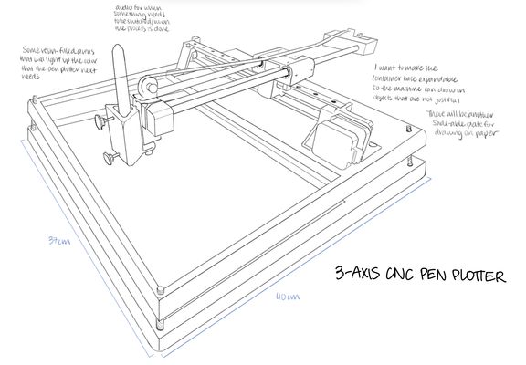
Original Sketch
Bill Of Materials
| Component | Quantity | Cost | Vendor | Lab / Personal Avaliability |
|---|---|---|---|---|
| Raspberry Pi 4 Model B - 4GB RAM | 1 | $120.00 | Adafruit | Yes |
| 32GB Sandisk microSD card | 1 | $26.00 | Amazon | Yes |
| 7 Inch HDMI Touchscreen LCD Display | 1 | $59.95 | Amazon | No |
| NeoPixel LED strip roll | 1 | $13.99 | Amazon | Yes |
| 1/2” plywood | 1 | $67.58 | Home Depot | Yes |
| XIAO ESP32-S3 | 1 | $7.12 | Seeed Studio | Yes |
| 1/8" Frosted Acrylic Sheet | 1 | $12.98 | Amazon | Yes |
| Behringer Bigfoot USB Microphone | 1 | $49.00 | Amazon | Yes |
| Dierya Keyboard | 1 | $29.99 | Amazon | Yes |
| MSI GM11 Mouse | 1 | $19.99 | Amazon | Yes |
| NEMA 17 Stepper Motor | 2 | $14.38 | Amazon | Yes |
| A4988 Polulu Motor driver | 2 | $7.69 | Amazon | Yes |
| V-Pulley with Bearing (V623ZZ) | 1 | $8.54 | Amazon | Yes |
| SG90 Micro Servo | 1 | $9.99 | Amazon | Yes |
| Bolts and Nuts Set | 1 | $23.99 | Amazon | Yes |
| DC Power Supply | 1 | $12.99 | Amazon | Yes |
| Buck Converter | 1 | $7.99 | Amazon | Yes |
| 5V 3A Power Supply | 2 | $17.99 | Amazon | Yes |
| GT2 Timing Pulley | 1 | $6.99 | Amazon | Yes |
| GT2 Idler Pulley | 1 | $7.99 | Amazon | Yes |
| 6mm x 41mm Black Flower Metal Fastener | 4 | $9.44 | Walmart | Yes |
Total Price: 548.96 (Overestimate)
Total Price considering availability: $59.95
While the total price at face value is a hefty sum, I was majorly able to find components and parts within the lab and from my own home. There were some parts I found online for the BOM that overaccount for how much I used, which is why $548.96 is an overestimation of the cost of my project. There are also some components that can easily be replaced by a less expensive alternative (such as the mouse and microphone) but those were the ones that were personally available to me.
Application of Weeks
| Week | Application |
|---|---|
| Week 2: Computer-aided design | I designed components of my machine and the cutouts of my wooden base in Fusion360 |
| Week 3: Computer controlled cutting | I laser-cut frosted acrylic side panels to diffuse the light from my LEDs and also openings on one of the panels to provide access to buttons and barrel jacks |
| Week 4: Embedded Programming | I programmed the XIAO ESP32-S3 to turn the NeoPixel LED strip on when a momentary SPST push button is pressed, and to turn the lights off when the button is pressed again |
| Week 5: 3D scanning and printing | I 3D printed out components for my LCD screen housing and my machine (servo housing, x-axis stabilizer, x-axis rod stabilizer) |
| Week 6: Electronics Design | I used KiCad to design my motorsheild PCB and my XIAO ESP32-S3 PCB |
| Week 7: Computer controlled machining | I used the CNC shopbot to mill out the wooden pieces of my base that I will assemble together |
| Week 8: Electronics Production | I used Carvera Milling machines to mill out my PCB boards and I soldered my components on in house |
| Week 9: Input devices | I programmed buttons (to start recording and to turn on the LED) and microphones (to record a voice prompt) as input devices |
| Week 10: Output devices | I programmed stepper motors, the microservo, the LCD screen, and NeoPixels as output devices |
| Week 16: System Integration | I integrated my systems by hiding the hardware wires and PCBs within the base of my pen plotter, allowing some holes for access to buttons and barrel jacks |
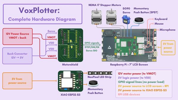
Hardware Diagram
Project Schedule
This is an outdated plan as I ended up carrying over to the 2026 cycle.
| Week | Dates | Goals/Tasks |
|---|---|---|
| Week 1 | April 28 – May 4 | Get Speech-to-Text + Touchscreen Working - Set up ReSpeaker 2-Mic Pi Hat - Install/test speech-to-text software (Vosk, Google STT, or similar) - Confirm Raspberry Pi can capture voice and convert it to text |
| Week 2 | May 5 – May 11 | Connect Speech-to-AI - Set up OpenAI ChatGPT API access (or local AI model) - Send recognized text to ChatGPT - Get a text response from ChatGPT - Display AI response on Pi (command line or touchscreen) |
| Week 3 | May 12 – May 18 | Machine Construction - Assemble the 3-axis pen plotter - Install motors, belts, lead screws, or rails - Mount the pen holder - Wire up the stepper motors, servo motors, limit switches - Test manual motor movement (basic electronics check) |
| Week 4 | May 19 – May 25 | G-code Generation Basic - Write a simple Python script that takes AI output and generates basic G-code commands (ex: square, circle) - Test manually entering sample commands and getting G-code - Start defining simple drawing "templates" |
| Week 5 | May 26 – May 31 | Machine Movement - Set up GRBL communication (pySerial or UGS) - Test sending basic G-code to pen plotter (move X, Y, Z manually) - Connect the full chain: voice → AI → G-code → movement (basic test!) - Start troubleshooting any mechanical or wiring issues |
| Week 6 | Jun 1 – May Jun 7 | Full System Integration + Polish - Full system test: voice → AI → G-code → machine drawing - Finish touchscreen UI (edit/send command) - Final video/photo documentation - Finish website and final project presentationThis is a sketch of my idea: |
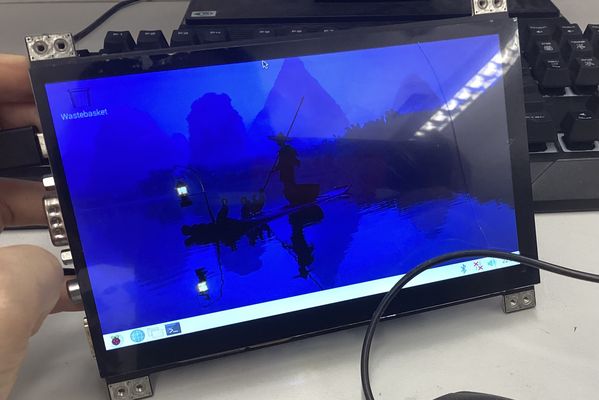
Touchscreen - Raspberry Pi 4
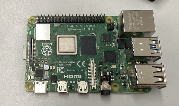
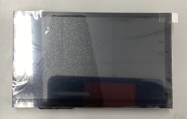
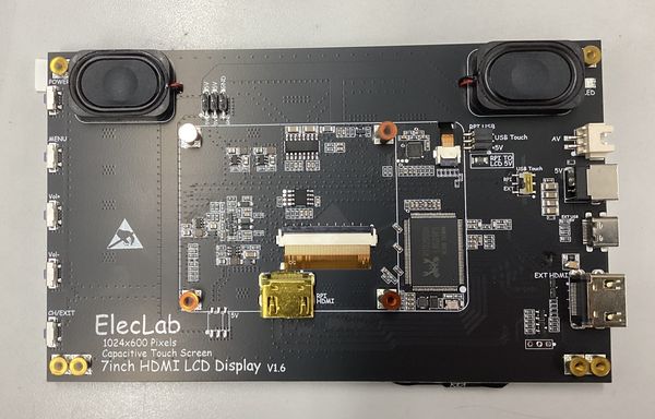
When I purchased the 7 Inch HDMI Touchscreen LCD Display it came with instructions on how to connect it to a Raspberry Pi. Even so, because it was my first time working with a Raspberry Pi, I was still confused. When I tried searching for tutorials online, a lot of them already assumed I had some base level of knowledge I didn't.
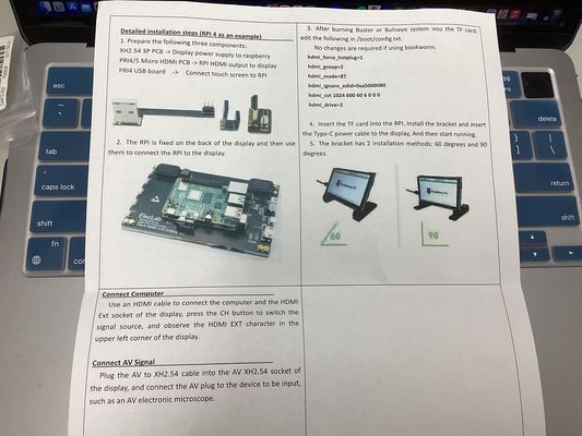
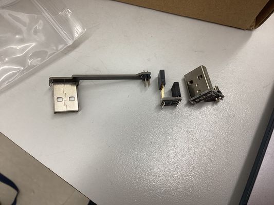
Figuring out where each of the three connective parts went was not necessarily the hardest part, but installing the driver was. I ended up following this tutorial to power it on even though it was different than what I had.
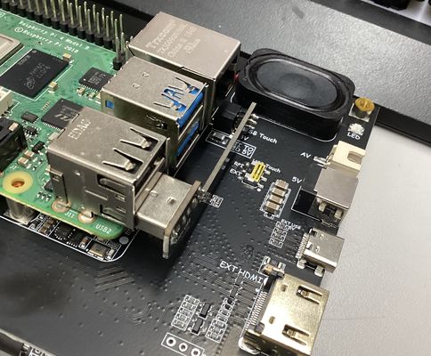
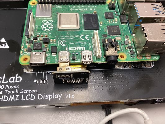
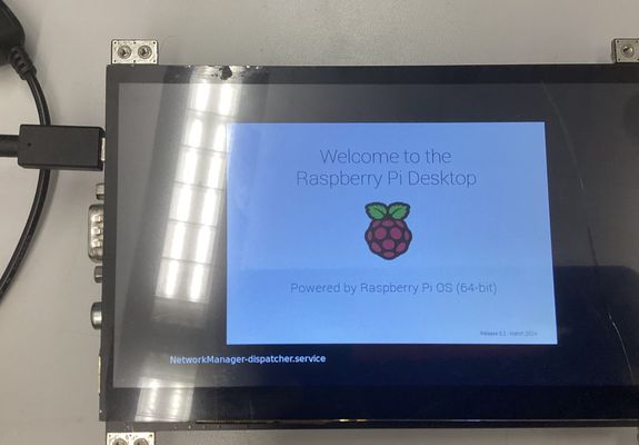
After that, I just inserted the MicroSD chip with the driver and powered it on and I got to the landing page.
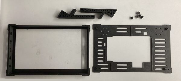
For the screen case, I used an open-sourced case that came with my screen.
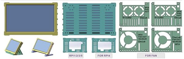
These were the printed parts
Behringer BigFoot Podcast Microphone
Microphone Setup and Testing
To figure out how to detect and configure my microphone device through the Raspberry Pi, I consulted Claude in this conversation.
To see if my microphone was detected by the Raspberry Pi, I used lsusb
kathrynwu@raspberrypi:~ $ lsusb
Bus 002 Device 001: ID 1d6b:0003 Linux Foundation 3.0 root hub
Bus 001 Device 005: ID 1379:1104 Behringer....... BIGFOOT
Bus 001 Device 004: ID 0db0:0d11 Micro Star International MSI GM11 Gaming Mouse
Bus 001 Device 003: ID 1a2c:9901 China Resource Semico Co., Ltd DIERYA 61SE
Bus 001 Device 002: ID 2109:3431 VIA Labs, Inc. Hub
Bus 001 Device 001: ID 1d6b:0002 Linux Foundation 2.0 root hub
To see recording devices, I used arecord -l and the output tells me my device, BigFoot, is on card 3, which is necessary information to know in the future when trying to record.
kathrynwu@raspberrypi:~ $ arecord -l
**** List of CAPTURE Hardware Devices ****
card 3: BIGFOOT [BIGFOOT], device 0: USB Audio [USB Audio]
  Subdevices: 1/1
  Subdevice #0: subdevice #0
To see sound devices, I used aplay -l
kathrynwu@raspberrypi:~ $ aplay -l
**** List of PLAYBACK Hardware Devices ****
card 0: vc4hdmi0 [vc4-hdmi-0], device 0: MAI PCM i2s-hifi-0 [MAI PCM i2s-hifi-0]
  Subdevices: 1/1
  Subdevice #0: subdevice #0
card 1: vc4hdmi1 [vc4-hdmi-1], device 0: MAI PCM i2s-hifi-0 [MAI PCM i2s-hifi-0]
  Subdevices: 1/1
  Subdevice #0: subdevice #0
card 2: Headphones [bcm2835 Headphones], device 0: bcm2835 Headphones [bcm2835 Headphones]
  Subdevices: 8/8
  Subdevice #0: subdevice #0
  Subdevice #1: subdevice #1
  Subdevice #2: subdevice #2
  Subdevice #3: subdevice #3
  Subdevice #4: subdevice #4
  Subdevice #5: subdevice #5
  Subdevice #6: subdevice #6
  Subdevice #7: subdevice #7
card 3: BIGFOOT [BIGFOOT], device 0: USB Audio [USB Audio]
  Subdevices: 1/1
  Subdevice #0: subdevice #0
Then, to record, I used arecord -D hw:3,0 -f cd -d 5 test.wav
Note: The arecord function is something you can customize, but it's very syntax-sensitive. An extra space anywhere can lead to errors.
- -D hw:3,0 means the record function uses card 3
- -f cd means it uses CD quality (16 bit 44100 hz)
- -d 5 means it records for a duration of 5 seconds
To play the recorded audio back, I used aplay test.wav
To hear the audio that was playing, I plugged a Sony headphone with a jack into my microphone. My mistake originally was pluging it into my Rapsberry Pi, when it should have gone into to the Behringer microphone. After that, I could hear what I said through aplay.
OpenAI Whisper Transcription
The next step was to use OpenAI Whisper to transcript my speech, the .wav file, to text. I first needed to install OpenAI Whisper, which is free and can run locally on my Pi.
I ran:
pip install openai-whisper --break-system-packages
During the download, I got these errors about how some directories were added to local bin and not path:
'/home/kathrynwu/.local/bin' which is not on PATH.
  Consider adding this directory to PATH or, if you prefer to suppress this warning, use --no-warn-script-location.
  WARNING: The script tqdm is installed in '/home/kathrynwu/.local/bin' which is not on PATH.
  Consider adding this directory to PATH or, if you prefer to suppress this warning, use --no-warn-script-location.
  WARNING: The script isympy is installed in '/home/kathrynwu/.local/bin' which is not on PATH.
  Consider adding this directory to PATH or, if you prefer to suppress this warning, use --no-warn-script-location.
Claude told me to run this to add them all to my path
echo 'export PATH="$HOME/.local/bin:$PATH"' >> ~/.bashrc && source ~/.bashrc
At this point, I was ready to translate my previous test script using
whisper test.wav --model base --language English
But got this error:
/home/kathrynwu/.local/lib/python3.11/site-packages/whisper/transcribe.py:132: UserWarning: FP16 is not supported on CPU; using FP32 instead
  warnings.warn("FP16 is not supported on CPU; using FP32 instead")
Illegal instruction
Illegal instruction is telling me that the base model is too big for my Pi and I should use the tiny version instead. So, I ran this prompt instead:
whisper test.wav --model tiny --language English
But even with tiny it did not work, so I was reccomended to use faster-whisper, which is allegedly better for the Pi. To use faster-whisper, I needed to upload a python code, transcribe.py, and edited it using nano transcribe.py with this content:
from faster_whisper import WhisperModel

# Load the model
model = WhisperModel("small", device="cpu", compute_type="int8")

# Transcribe the audio file
segments, info = model.transcribe("test.wav", language="en")

# Print the transcribed text
for segment in segments:
    print(segment.text)
With faster-whisper, I used the small model, and it worked!
kathrynwu@raspberrypi:~ $ nano transcribe.py
kathrynwu@raspberrypi:~ $ nano transcribe.py
kathrynwu@raspberrypi:~ $ python3 transcribe.py
Warning: You are sending unauthenticated requests to the HF Hub. Please set a HF_TOKEN to enable higher rate limits and faster downloads.
 Testing. Draw me a flower, please.
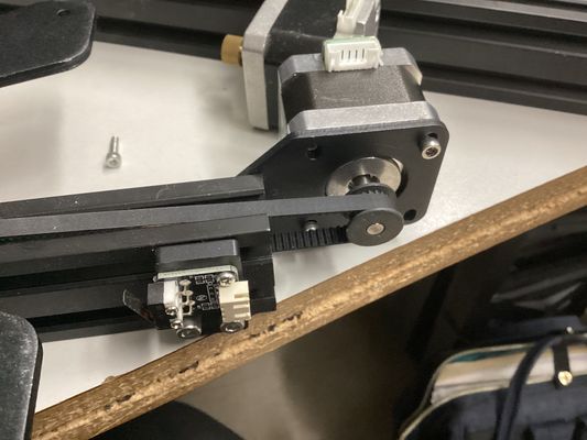
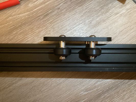
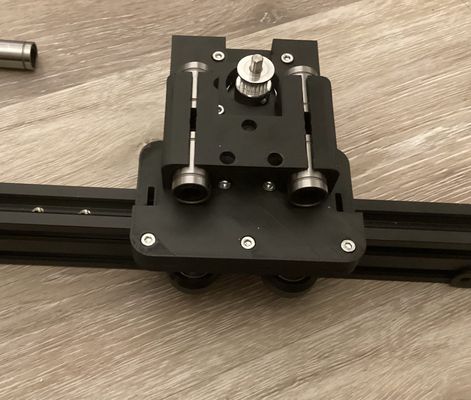
Pen Plotter Mechanics
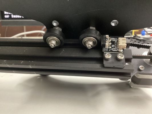
Using a 12 inch 40x80mm Aluminum T-Slot Extrusion, I attached a stepper motor pulley system that will allow the motor to control the movement of the x-axis.
This is the way the v-slot wheels connected to move along the aluminum extrusion. It also shows how the limit switch is pressed down as the wheels make contact and reach the end of the rail.
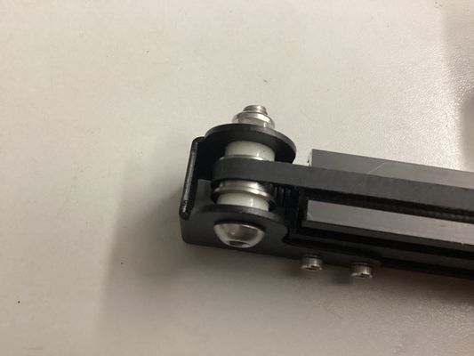
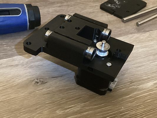
This is the stepper belt and timing pulley.
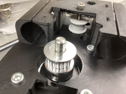
This shows the belt end and the idler pulley.
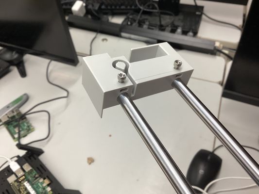
3D Printing
These parts were inspired by the DIY Machines CNC Drawing Machine and customized for my project.
These were the components I had to 3D print.

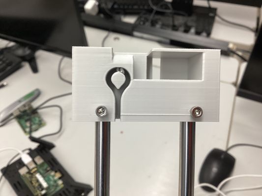
In my first iteration of the rod carriage, I based it off of a piece that had pre-existing holes where the screws would need to go.
I then rounded the edges, and tested the fit withh the v-slot wheels screwed on.
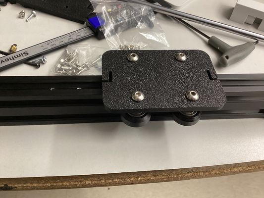
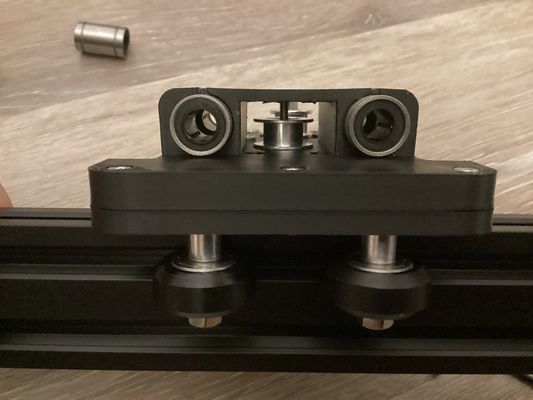
I then printed out the rod carriage and inserted the bearings inside the holes. I also attached the pulley mechanism.
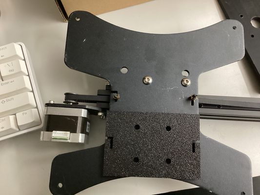
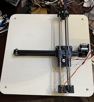
I attached this to the first rod carriage, which allowed it to be moved with the timing belt.
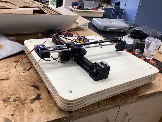
I also printed out the y-axis parts and attached the entire y-axis components with a linear rod.
This is what my fully assembled machine looked like.
This is how the servo moves:
This is how the x-axis moves:
And this is how the y-axis moves:
Plotter Movement
A4988 Potentiometer Adjustment
How to set it:
- Find your stepper motor's rated current per phase on its datasheet or label
- Power your board with logic voltage only (motor power off)
- Measure the voltage on the pot's wiper (center of the screw) relative to GND using a multimeter
Note: An easy way to be able to measure the voltage while you're turning a philip's head screwdriver is to use an alligator clip between the red probe and the head of the screwdriver so you're getting constantly accurate readings
- The formula is: Vref = Imax × 8 × Rsense
The maximum motor current for my Nema 17s is 2 amps
Vref = I_max × 0.4 Vref = 2 × 0.4 = 0.8V
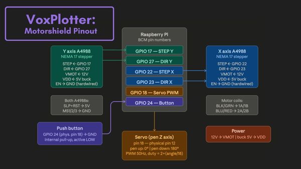
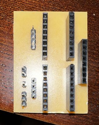
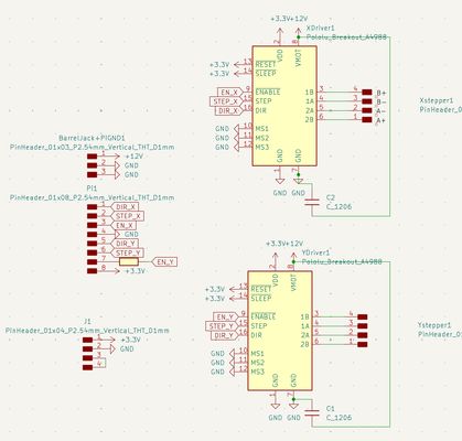
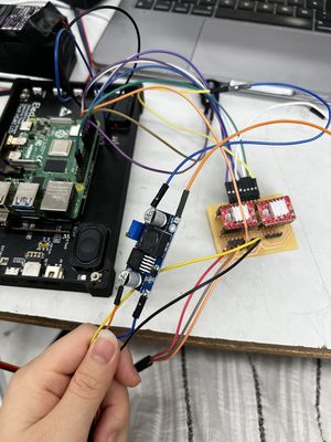
Motorshield Breakout Board
To control my motors, I needed a motorshield, so I designed a custom one for my two steppers and microservo. Ultimately, they would be encoded by my Raspberry Pi, so I needed pin headers going off of the board to be connected to my Pi through juper wires.
| Signal | Connection |
|---|---|
| Pi GPIO 17 | Y axis A4988 STEP |
| Pi GPIO 27 | Y axis A4988 DIR |
| Pi GPIO 22 | X axis A4988 STEP |
| Pi GPIO 23 | X axis A4988 DIR |
| Pi GPIO 18 | Servo signal |
| Pi GPIO 24 | Button leg 1 |
| Pi GND | Button leg 2 |
| Pi GND | Common GND rail |
| Buck converter 5V | A4988 VDD (both drivers) |
| Buck converter 5V | A4988 SLEEP + RESET (both drivers) |
| Buck converter GND | Common GND rail |
| 12V supply | A4988 VMOT (both drivers) |
| 12V supply GND | Common GND rail |
| A4988 MS1/MS2/MS3 | GND (both drivers) |
| A4988 ENABLE | GND hardwired (both drivers) |
| Y axis motor black | Y A4988 1A |
| Y axis motor green | Y A4988 1B |
| Y axis motor blue | Y A4988 2A |
| Y axis motor red | Y A4988 2B |
| X axis motor black | X A4988 1A |
| X axis motor green | X A4988 1B |
| X axis motor blue | X A4988 2A |
| X axis motor red | X A4988 2B |
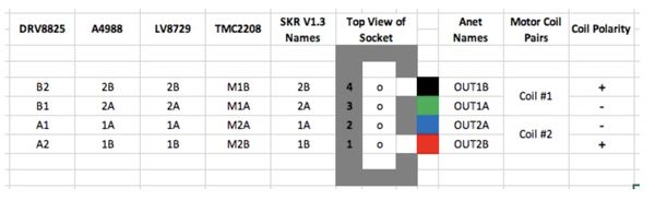
Or, better represented by this diagram made by Claude:
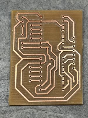
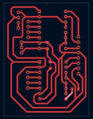
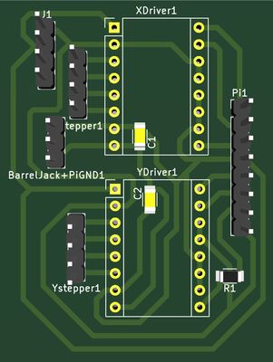
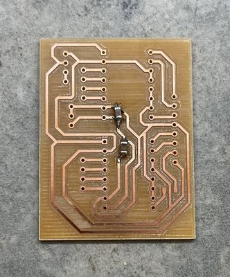
Note: Most of the issues I ran into were with this board. With each iteration I realized issues in my design, so the first design below is not my final, working one.
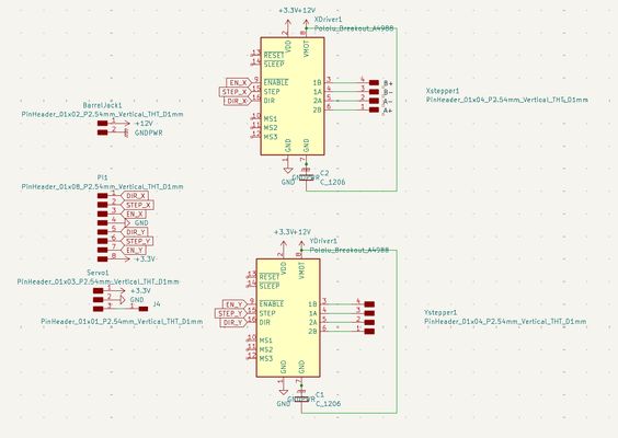
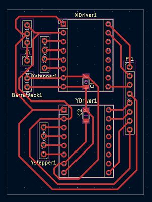
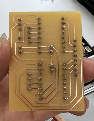
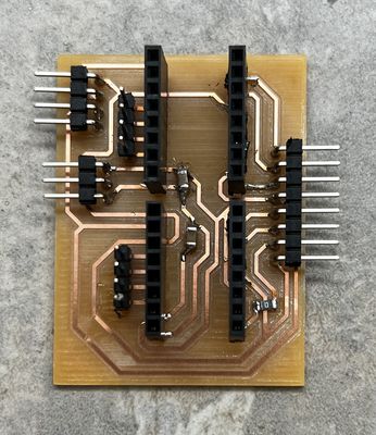
With this board, I soldered on my pinheaders on the flip side, as it made soldering on the copper side easier. However, I forgot that working on the back leads to the entire component being flipped. So, this board would definitely not work. Surely enough, when I tested it, the stepper motors would not lock or power on.
While troubleshooting, I realized more issues with this design. I had left MS1, MS2, and MS3 floating which means my motors will work on Full Step Mode. With the Polulu A4988 driver, these pins have internal pull-down resistors and I should be able to leave them floating. However, I was using a clone board, and I wasn't fully willing to trust that, so I revised my design to tie them together and to ground.
Something else is that I neglected to tie Sleep (SLP) and Reset (RST) together and to 5V. This was a change I added in my subsequent design.
However, this board was still not working. I decided to test the driver on a breadboard at this point and try to figure out everything that was going wrong once and for all.
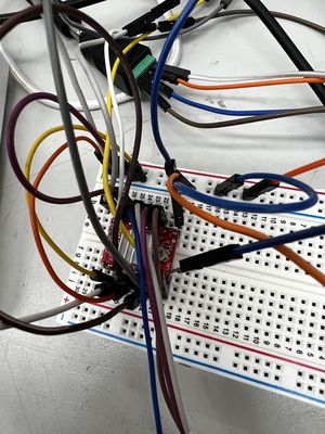
With the breadboard, I realized that my error was that I had mistaken the order of the stepper motors wires on board. To be sure, I used the resistance measuring function on my multimeter to check which coils were a pair.
I found that BLK/GRN → 1A/1B and BLU/RED → 2A/2B. Thus, the order of the wires should be red, blue, black green (not black, green, blue, red as I had it before.)
On the breadboard, I was able to get a motor powered and turning.
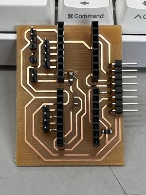
Furthermore, I needed a common ground between my motor drivers, servo motor, and the Raspberry Pi. I also needed to tie Enable to ground. I updated my PCB design by adding a trace between the grounds to a pin that I can connect to my Raspberry Pi's ground pin via a jumper wire.
This ended up being my final, working design:
Now, when I tried to power a motor with my new breadboard, the motor would spin, moving an axis. In this video, it was the x-axis:
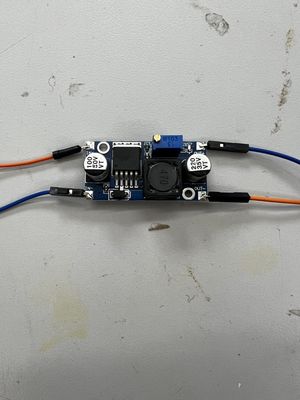
Buck Converter
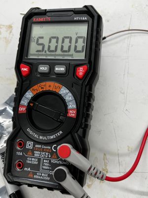
I also needed a buck converter to convert 12V to 5V. To ensure the buck outputs only 5V, I used a multimeter and alligator clips. I clamped the black probe onto OUT- and the red probe onto OUT+. I adjusted the potentiometer using a flathead screwdriver until the voltage reading on my multimeter was 5V.
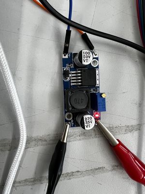
After doing so, I soldered wires onto the OUT- and OUT+ of the buck. The buck converter inputs came from the 12V and GND of the 12V DC power source's barrel jack. Then, I wired the outputs to the 5V pin on my motorsheild breakout board to supply the VDD of the motor drivers and the servo.
Servo
I connected the servo to one of my Pi's GPIO pins and ran a test to see whether I could control it through terminal.
import RPi.GPIO as GPIO
import time

SERVO_PIN = 18
GPIO.setmode(GPIO.BCM)
GPIO.setup(SERVO_PIN, GPIO.OUT)

pwm = GPIO.PWM(SERVO_PIN, 50)
pwm.start(0)

def pen_up():
    pwm.ChangeDutyCycle(2 + (0 / 18))
    time.sleep(0.3)
    pwm.ChangeDutyCycle(0)

def pen_down():
    pwm.ChangeDutyCycle(2 + (90 / 18))
    time.sleep(0.3)
    pwm.ChangeDutyCycle(0)

try:
    print("Pen down...")
    pen_down()
    time.sleep(1)
    print("Pen up...")
    pen_up()
    time.sleep(1)
    print("Done!")
except KeyboardInterrupt:
    pass
finally:
    pwm.stop()
    GPIO.cleanup()
In this video, it shows the servo arm moving as encoded:
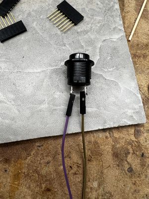
Button
I also soldered wires onto a momentary push button to be plugged into the Pi. The purpose of this button is to begin the voice reading command when pressed.
I ran a python code to make sure the button could be sensed:
import RPi.GPIO as GPIO
BTN_PIN = 24
GPIO.setmode(GPIO.BCM)
GPIO.setup(BTN_PIN, GPIO.IN, pull_up_down=GPIO.PUD_UP)
try:
    while True:
        if GPIO.input(BTN_PIN) == GPIO.LOW:
            print("Button pressed!")
except KeyboardInterrupt:
    GPIO.cleanup()
In this video, it shows how the button, when pressed, indicates that the button was pressed which means its signal was getting through:
Gcode Testing
Before I tested the full pipeline, I tested the gcode of some more basic functions. These gcodes are downloadable in the files at the bottom of the page, but I am also embedding it here in my site for easier access:
I created these .gcode files that are ready to use by my plotter.py script by first creating a folder:
mkdir -p ~/gcode
then by creating the gcode file:
nano ~/gcode/testname.gcode
then pasting in the gcode script
G90          ; absolute coordinates
M5           ; pen up
G0 X0 Y0     ; go to origin
M3           ; pen down
G1 X50       ; draw 50mm right
M5           ; pen up
G28          ; return home
This example is for my machine to draw a line.
To only run the gcode file, I created a test script
nano ~/test_gcode.py
and pasted this in
import sys
sys.path.insert(0, '/home/kathrynwu')
from plotter import run_gcode

run_gcode('/home/kathrynwu/gcode/line.gcode')
I would run it with
python3 ~/test_gcode.py
And to test different gcode files you just changed the filename in the last line — for example:
run_gcode('/home/kathrynwu/gcode/diagonal.gcode') run_gcode('/home/kathrynwu/gcode/circle.gcode')
This is an example of my machine successfully running puzzle.gcode:
With puzzle.gcode having a combination of straight and diagonal lines, it shows how the machine is able to handle simultaneous axis motions. I had to hold down the x-axis because at this point I hadn't attached it to the wooden base yet.
Full Pipeline
This is the full pipeline, downloadable by clicking the link. What it encodes is this path:
- Program starts → all STEP and DIR pins set LOW
- Button pressed → record → transcribe → find gcode
- G-code runs → STEP and DIR pulse as needed to move motors
- G-code finishes → all STEP and DIR pins return to LOW (idle again)
- Wait for next button press…
To run it, the command I used was:
python3 plotter.py
I am also embedding it here in my site so it is easier to see:
"""
Voice-activated pen plotter — main pipeline
Hardware: Raspberry Pi + A4988 drivers + servo
Usage: python3 plotter.py
"""

import os
import re
import subprocess
import time
import RPi.GPIO as GPIO
from faster_whisper import WhisperModel

# CONFIG
GCODE_DIR = "/home/kathrynwu/gcode"
RECORD_SECONDS = 5
AUDIO_FILE = "/tmp/command.wav"
WHISPER_MODEL = "small"

# Pins (BCM)
STEP_Y = 17
DIR_Y = 27
STEP_X = 22
DIR_X = 23
SERVO_PIN = 18
BTN_PIN = 24

# Motion constants
STEPS_PER_MM = 5
STEP_DELAY = 0.01

# GPIO setup
GPIO.setmode(GPIO.BCM)
GPIO.setwarnings(False)
GPIO.cleanup()

for pin in [STEP_X, DIR_X, STEP_Y, DIR_Y]:
    GPIO.setup(pin, GPIO.OUT)
    GPIO.output(pin, GPIO.LOW)

GPIO.setup(SERVO_PIN, GPIO.OUT)
GPIO.setup(BTN_PIN, GPIO.IN, pull_up_down=GPIO.PUD_UP)

pwm = GPIO.PWM(SERVO_PIN, 50)
pwm.start(0)

def hold_idle():
    for pin in [STEP_X, DIR_X, STEP_Y, DIR_Y]:
        GPIO.output(pin, GPIO.LOW)

def pen_up():
    pwm.ChangeDutyCycle(2 + (0 / 18))
    time.sleep(0.5)
    pwm.ChangeDutyCycle(0)

def pen_down():
    pwm.ChangeDutyCycle(2 + (180 / 18))
    time.sleep(0.5)
    pwm.ChangeDutyCycle(0)

def move(step_pin, dir_pin, steps, direction):
    GPIO.output(dir_pin, direction)
    time.sleep(0.1)
    for _ in range(abs(steps)):
        GPIO.output(step_pin, GPIO.HIGH)
        time.sleep(STEP_DELAY)
        GPIO.output(step_pin, GPIO.LOW)
        time.sleep(STEP_DELAY)
    GPIO.output(step_pin, GPIO.LOW)
    GPIO.output(dir_pin, GPIO.LOW)

def move_mm(axis, mm):
    steps = int(abs(mm) * STEPS_PER_MM)
    direction = GPIO.HIGH if mm > 0 else GPIO.LOW
    if axis == 'x':
        move(STEP_X, DIR_X, steps, direction)
    else:
        move(STEP_Y, DIR_Y, steps, direction)

def move_xy(dx, dy):
    steps_x = int(abs(dx) * STEPS_PER_MM)
    steps_y = int(abs(dy) * STEPS_PER_MM)
    dir_x = GPIO.HIGH if dx > 0 else GPIO.LOW
    dir_y = GPIO.HIGH if dy > 0 else GPIO.LOW

    GPIO.output(DIR_X, dir_x)
    GPIO.output(DIR_Y, dir_y)
    time.sleep(0.1)

    total_steps = max(steps_x, steps_y)
    for i in range(total_steps):
        if i < steps_x:
            GPIO.output(STEP_X, GPIO.HIGH)
        if i < steps_y:
            GPIO.output(STEP_Y, GPIO.HIGH)
        time.sleep(STEP_DELAY)
        GPIO.output(STEP_X, GPIO.LOW)
        GPIO.output(STEP_Y, GPIO.LOW)
        time.sleep(STEP_DELAY)

    GPIO.output(STEP_X, GPIO.LOW)
    GPIO.output(STEP_Y, GPIO.LOW)
    GPIO.output(DIR_X, GPIO.LOW)
    GPIO.output(DIR_Y, GPIO.LOW)

def run_gcode(filepath):
    print(f"[plotter] Running: {filepath}")
    pen_up()

    cur_x, cur_y = 0.0, 0.0
    absolute = True

    with open(filepath) as f:
        for raw_line in f:
            line = raw_line.split(';')[0].strip().upper()
            if not line:
                continue

            tokens = line.split()
            cmd = tokens[0]

            def get_param(letter, default=None):
                for t in tokens[1:]:
                    if t.startswith(letter):
                        try:
                            return float(t[1:])
                        except ValueError:
                            pass
                return default

            if cmd == 'G90':
                absolute = True
            elif cmd == 'G91':
                absolute = False
            elif cmd == 'G28':
                pen_up()
                move_mm('x', -cur_x)
                move_mm('y', -cur_y)
                cur_x, cur_y = 0.0, 0.0
            elif cmd in ('G0', 'G1'):
                tx = get_param('X')
                ty = get_param('Y')

                if absolute:
                    new_x = tx if tx is not None else cur_x
                    new_y = ty if ty is not None else cur_y
                else:
                    new_x = cur_x + (tx or 0.0)
                    new_y = cur_y + (ty or 0.0)

                dx = new_x - cur_x
                dy = new_y - cur_y

                if abs(dx) > 0.001 and abs(dy) > 0.001:
                    move_xy(dx, dy)
                elif abs(dx) > 0.001:
                    move_mm('x', dx)
                elif abs(dy) > 0.001:
                    move_mm('y', dy)

                cur_x, cur_y = new_x, new_y

            elif cmd == 'G4':
                p = get_param('P', 0)
                s = get_param('S', 0)
                time.sleep(p / 1000.0 + s)

            elif cmd in ('M3', 'M03'):
                pen_down()
            elif cmd in ('M5', 'M05'):
                pen_up()

    pen_up()
    hold_idle()
    print("[plotter] Done.")

def record_audio():
    print(f"[voice] Recording {RECORD_SECONDS}s — speak now!")
    subprocess.run(
        ["arecord", "-D", "hw:3,0", "-f", "cd", "-d", str(RECORD_SECONDS), AUDIO_FILE],
        check=True
    )
    print("[voice] Done recording.")

def find_gcode(transcript):
    words = re.findall(r"[a-z0-9_]+", transcript.lower())
    available = {
        os.path.splitext(f)[0].lower(): os.path.join(GCODE_DIR, f)
        for f in os.listdir(GCODE_DIR)
        if f.endswith(".gcode")
    }
    for word in words:
        if word in available:
            print(f"[voice] Matched '{word}' → {available[word]}")
            return available[word]
    print(f"[voice] No match. Available: {list(available.keys())}")
    return None

def main():
    print("=== Pen Plotter Ready ===")
    model = WhisperModel(WHISPER_MODEL, device="cpu", compute_type="int8")

    hold_idle()

    try:
        while True:
            if GPIO.input(BTN_PIN) == GPIO.LOW:
                time.sleep(0.05)
                record_audio()
                segments, _ = model.transcribe(AUDIO_FILE, language="en")
                transcript = " ".join(seg.text for seg in segments)
                print(f"[voice] Heard: '{transcript}'")

                gcode_path = find_gcode(transcript)
                if gcode_path:
                    run_gcode(gcode_path)

                hold_idle()

            time.sleep(0.05)

    except KeyboardInterrupt:
        print("\n[plotter] Shutting down.")
    finally:
        hold_idle()
        pwm.stop()
        GPIO.cleanup()

if __name__ == "__main__":
    main()
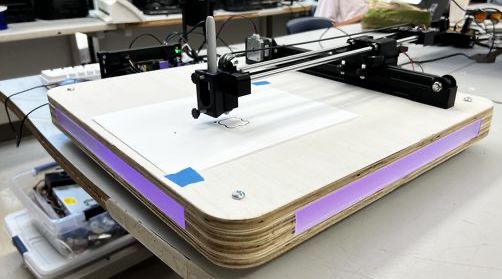
Hero Shot
This is my hero shot of the Raspberry Pi controlling the entire pipeline:
- The first button I pressed was to power on the LEDs
- The second button I pressed began voice recording
- After it heard my prompt, it translated it to text, located the gcode and drew out the puzzle shape
Plotter Base
Instead of an adjustable design that I was thinking of before, I decided to design my base to be more cosmetic. Inspired by Angelina's Pomo Desk, I wanted there to be an LED lighting aspect.
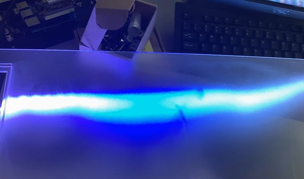
Frosted Acrylic Panels
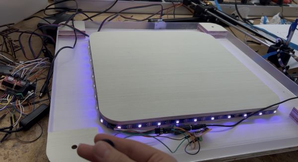
Originally, I was going to do acrylic panels, but in the lab I also found frosted ones, which I felt would give my machine a better ambiance. I found one sheet that seemed to have enough room for the panels I wanted to use. To test how it would look like in reality, I positioned the sheet over the LEDs at a similar distance.
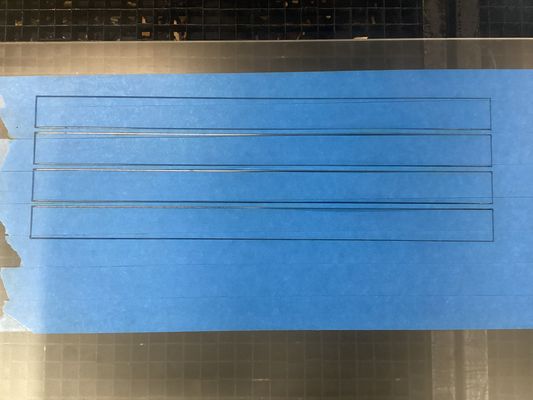
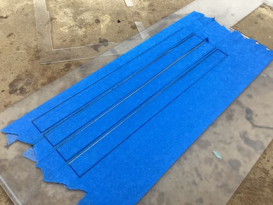
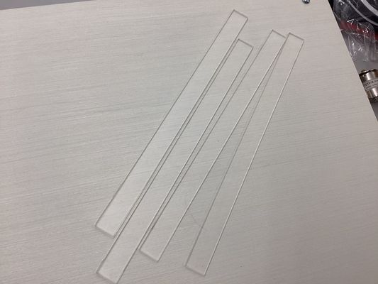
I decided I really liked how it looked, so I made some rudimentary designs based on the rectangular holes I wanted my panels to go through. I tested the dimensions using carboard first, because I did not have enough of the frosted acrylic to gamble on error.
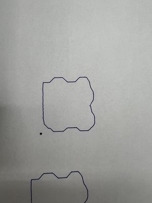
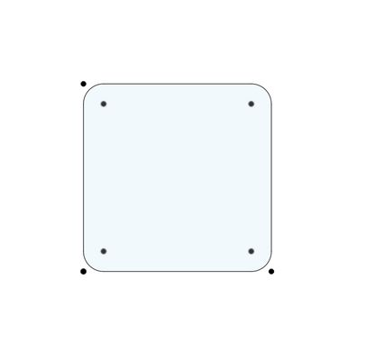
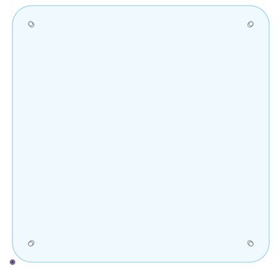
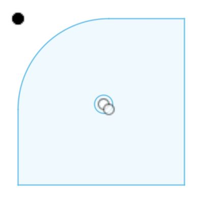
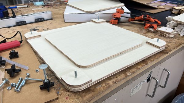
Plywood Structure
The design I went with included some stacking. I had two large curved rectangles with holes in each corner. There were two supportive squares in the center where the LED strip will wrap around. Then, in each corner, there are quarter-spheres, also with holes in them for where they will be secured with the base and upper wooden plates. I designed the shapes in Fusion 360 and exported my design as .dwg fils for Corel Draw and .dxf files for Aspire.
From left to right, these would be the center piece (x1), the bottom and top panels (x2), and the edge piece (x8):
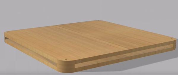
This is what it looked like assembled:
I did some sample tests using cardboard on the laser cutter.


Since it ended up exactly as I imagined, I moved onto milling the pieces out on the ShopBot, and this was the finished cut.

I found knobs in the lab to use as well as a screw with a flat round end. The knob allowed me to screw it to the tightness I wanted.

This was a shot midway through assembling.
This was the final result of the wooden base with all the frosted panels attached:
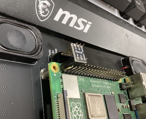
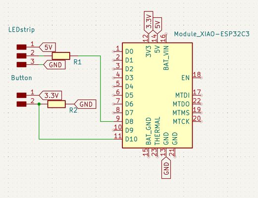
LED Lighting
| From | To |
|---|---|
| 5V Power Source | XIAO 5V pin |
| XIAO 5V | LED Strip 5V |
| GND | LED Strip GND |
| GND | Button leg 2 + 10kΩ |
| XIAO 3.3V | Button leg 1 |
| XIAO D10 | Button leg 1 (same leg as 3.3V) |
| XIAO D8 | 300Ω → LED Strip Din |
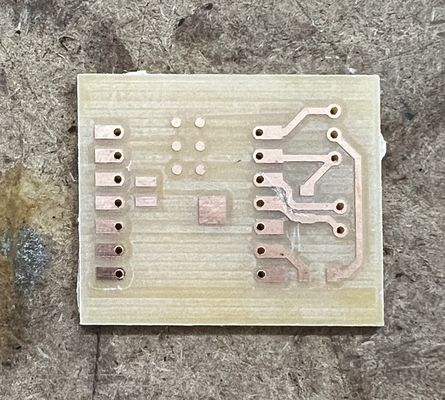
I used KiCAD to design the circuit based on my above plan.
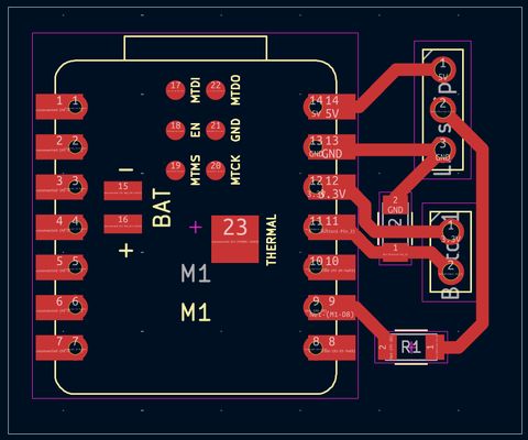
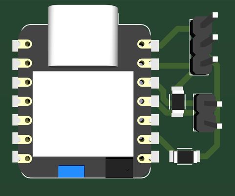
Once it was milled out, I soldered on the components and headers and wired it up.
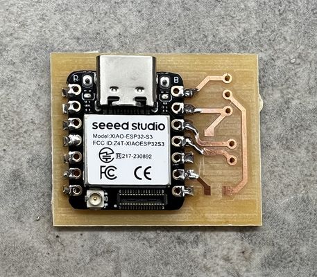
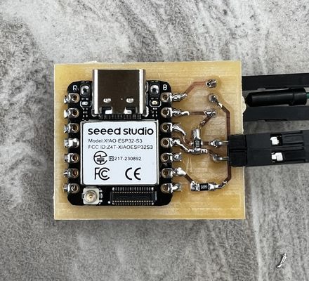
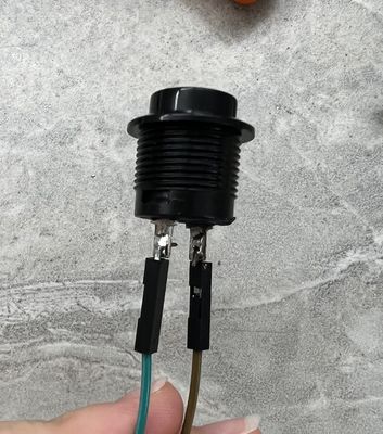
I soldered two male-to-female wires to either end of my momentary push button, which is my input device.
When programming, I powered off the 5V through the barrel jack and only used the USB-C from my Macbook to power on the XIAO ESP32-S3.
I used Arduino IDE to encode my microcontroller with this code (file located at the bottom of this page)
#include <FastLED.h>


#define NUM_LEDS    30
#define DATA_PIN    7
#define BUTTON_PIN  9


CRGB leds[NUM_LEDS];
bool stripOn = false;
bool lastButtonState = LOW;
float pulseStep = 0;


void setup() {
 Serial.begin(115200);  // ADD THIS
 FastLED.addLeds<WS2812B, DATA_PIN, GRB>(leds, NUM_LEDS);
 FastLED.setBrightness(255);
 pinMode(BUTTON_PIN, INPUT);
}


void loop() {
 bool buttonState = digitalRead(BUTTON_PIN);
 Serial.println(buttonState);  // ADD THIS — watch serial monitor


 if (buttonState == HIGH && lastButtonState == LOW) {
   stripOn = !stripOn;
   delay(150);
 }
 lastButtonState = buttonState;


 if (stripOn) {
   float pulse = (sin(pulseStep) + 1.0) / 2.0;
   uint8_t r = 150 - (50 * pulse);
   uint8_t g = 0;
   uint8_t b = 255 - (55 * pulse);
   fill_solid(leds, NUM_LEDS, CRGB(r, g, b));
   pulseStep += 0.03;
 } else {
   fill_solid(leds, NUM_LEDS, CRGB::Black);
   pulseStep = 0;
 }


 FastLED.show();
 delay(10);
}


#include <FastLED.h>


#define NUM_LEDS    42
#define DATA_PIN     7
#define BUTTON_PIN   9


CRGB leds[NUM_LEDS];
bool stripOn = false;
bool lastButtonState = LOW;
unsigned long lastDebounceTime = 0;
unsigned long debounceDelay = 200;
float pulseStep = 0;


void setup() {
 FastLED.addLeds<WS2812B, DATA_PIN, GRB>(leds, NUM_LEDS);
 FastLED.setBrightness(255);
 pinMode(BUTTON_PIN, INPUT);
}


void loop() {
 bool buttonState = digitalRead(BUTTON_PIN);


 if (buttonState == HIGH && lastButtonState == LOW) {
   if (millis() - lastDebounceTime > debounceDelay) {
     stripOn = !stripOn;
     lastDebounceTime = millis();
   }
 }
 lastButtonState = buttonState;


 if (stripOn) {
   float pulse = (sin(pulseStep) + 1.0) / 2.0;
   uint8_t r = 150 - (50 * pulse);
   uint8_t g = 0;
   uint8_t b = 255 - (55 * pulse);
   fill_solid(leds, NUM_LEDS, CRGB(r, g, b));
   pulseStep += 0.03;
 } else {
   fill_solid(leds, NUM_LEDS, CRGB::Black);
   pulseStep = 0;
 }


 FastLED.show();
 delay(10);
}
And it would light up when the button is pressed, then turn off when pressed again.
With the led's working, I removed the blue backing of the tape on the other side of the strip and attached it along the center piece of my wooden base.
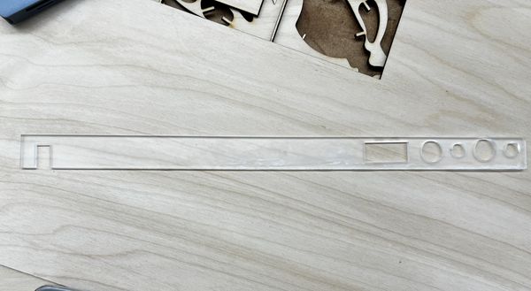
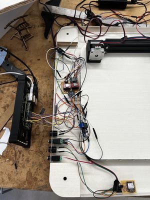
System Integration
To integrate my system, I planned to hide all the wires inside my wooden base. However, there were still certain components I needed outside access to: the buttons and barrel jacks.
I designed the parts to be cut out on CorelDraw:
- Panel dimensions: 365mm x 24mm
- Button diameter: 15mm
- Screw terminal: diameter 10mm
- Pi wires cutout: 32mm x 15mm
- Plotter wires cutout: 20mm x 10mm

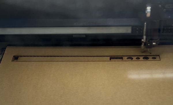
First, I did a practice cut on cardboard:
Then, I made some tweaks in the design for better fit, and cut it out on the arylic panel:
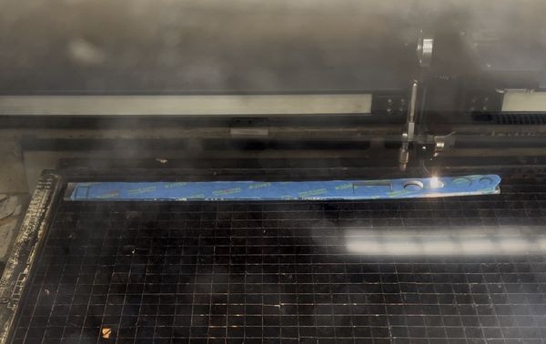
Note: I learned that taping the side facing the laser cuts better, prevents it from melting, and keeps it clean of debris
This was the acrylic panel with the smaller holes being for the barrel jacks and the larger ones for the buttons. The large rectangle on the right is for the wires coming out of the Raspberry Pi and the smaller rectangle on the left is for the stepper motor and microservo wires that need to connect to the machine.
This is the hardware situation after installing my acrylic panel.
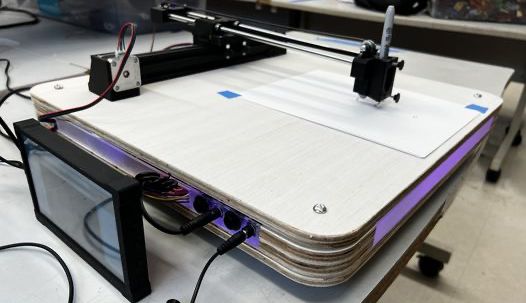
After putting on the top panel, and screwing it in, this was the final system integration.
Question Responses
(that haven't yet been answered)
Who’s done what beforehand?
My project is inspired by Jack Hollingsworth's Ouiji Board, which uses ChatGPT to generate responses and control stepper motors to physically "move" a planchette. I learned about this through the ouiji board group project from last year’s Fab Academy cycle. Both projects demonstrated how artificial intelligence could be used for real-world motion control through G-code to command stepper motors. I was especially drawn to the voice-activated aspect, which made the interaction feel more natural and autonomous. I wanted to explore that further in a visual way.
The base is inspired by Angelina Yang's Pomo-Desk, with its internal LED strip and aesthetic lighting.
What worked? What didn’t?
My original idea for AI to G-code was not really plausible. Mr. Nelson made the suggestion that I could have AI generate an image then use the image in a g-code making software. After the meeting, Mr. Dubick also told me I could go the route where I pre-code certain images that the machine draws properly. Then, I'd just voice the command "Draw me a ___" with one of the pre-developed images. This would make it more reliable.
How was it evaluated?
This project was evaluated based off the accuracy of the voice recognition, mechanical performance, the user interface usability, system integration/stability/quality, safety, and overall user experience.
What are the implications?
I think this project is meant to be an overlap between something creative and something more technical. It opens up possibilities for more human-machine collaboration, especially as/when AI tech advances. It makes digital fabrication more accessible if its only based on voice commands, although my project is just a nascent version of the potential with voice to output machination.
But additionally, the modular structure of the system (voice input, Raspberry Pi processing, motor control) makes it extensible beyond drawing. With modifications, it could evolve into a general-purpose voice-driven fabrication platform for laser cutting, CNC milling, or even robotic interaction.
Acknowledgments
I would like to thank Mr. Dubick, Dr. Taylor, and Mr. Budzichowski for their guidance, encouragement, and support throughout this project. Thank you for always being willing to provide feedback, help with challenges as they arose, and especially for keeping the lab available at odd and long hours. I also thank Mr. Roberto Delgado, my global evaluator, for reviewing my assignments over the past year-and-a-half.
I'm forever grateful to my friends and parents who contributed and supported my work along the way. This project and Fab Academy in general have been an incredibly rewarding experience, and I am grateful for all the people who helped make it possible.
Files:
- Machine Parts
- Machine Base
- Plotter Code
- Gcodes
- Motorshield KiCad
- Motorsehild Milling
- XIAO ESP32-S3 Code
- XIAO ESP32-S3 KiCad
- XIAO ESP32-S3 Milling
- Acrylic Panel Cutting