Computer-Controlled Machining
- make (design+mill+assemble) something big (~meter-scale)
- extra credit: don't use fasteners or glue
- extra credit: include curved surfaces
Design a big thing
-
Idea
The material Chaihuo FABLAB provide is high density fiberboard with 18mm thicknessTo avoid wasting, I want to using this chance to build up some big models relate to the final project. Considering the strength of the CNC-manufactured parts, I plan to make the following components: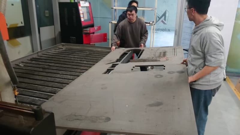
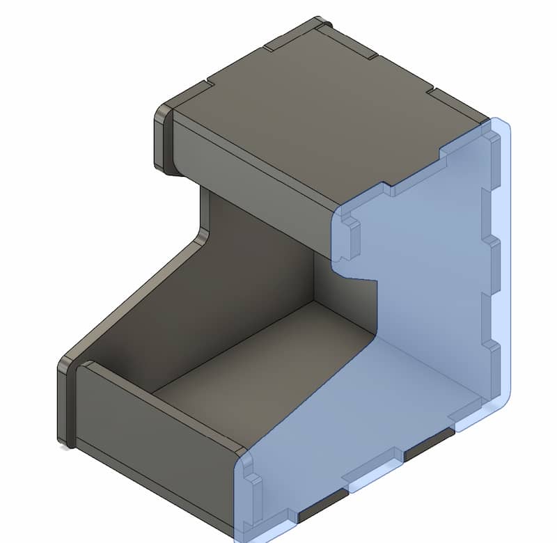
- A game shell, which is strong enough for transporting and protecting the internal components of the game project
Design concept
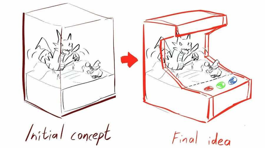
For the initial concept, I think just designing a simple rectangular box to cover the game, but the appearance is boring and featureless. So I want the shell have a theme,
want the sharp of the shell can be thought that relates to playing game, and finally is inspired by arcade machines. - A magic staff, which is strong enough to be held and waved during by the player
Design concept
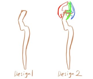
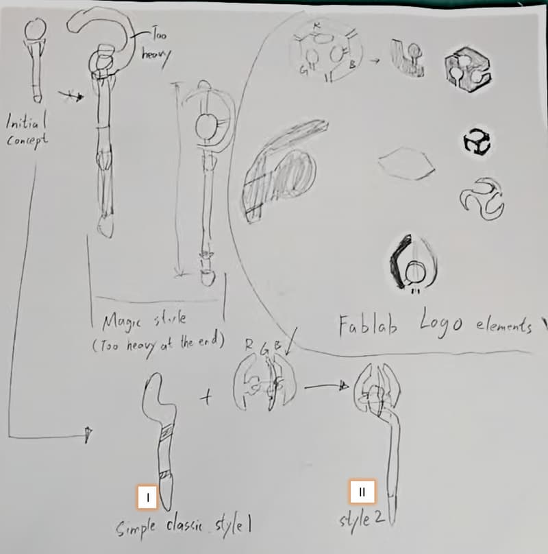
I consider some style of the staff. A design is reference from the fantasy style, always has a large "C" sharp at the top. But it will become a little bit to heavy to wave, I choose a simple classic sharp (I).
My ideal theme is related to RGB color, and I find that the FABLAB logo has exactly this three color, so I also try to add the logo elements into the staff design (II).
- A game shell, which is strong enough for transporting and protecting the internal components of the game project
-
Design
The shell is basically full with connection parts in every edge, so I will just Fusion360 to design. And the staff is basically combination of 2D curve, I'll use CorelDraw to design.Shell - Fusion360
Design Process
To make the design adjustable, first I set the parameter of the following dimension. so in the further design, I'll use the parameter instead of a fix number.
I'll start from the back board. Basically use the width and height parameter to create a rectangle, and add some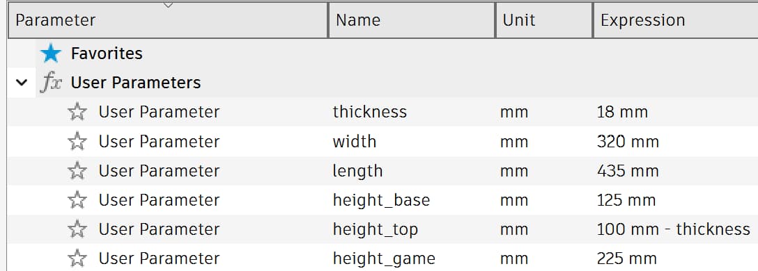 For the further steps, just repeat 'Create Sketch' to sketch the side view and then use 'Extrude' to form the solid model.
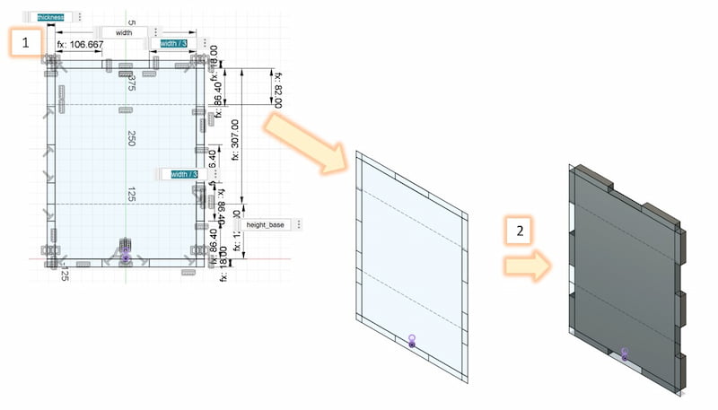 Safety
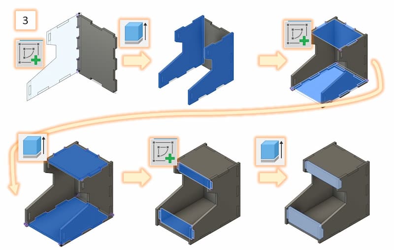
As there are many sharp angle in the corner of the board, it will be easy to stab someone. To make it safe, I usefilletfunction to turn the corner round. The fillet radius is set as same as thethicknessparameter.Also to make the connecting joints plug in easier, all the convex joints is also be rounded by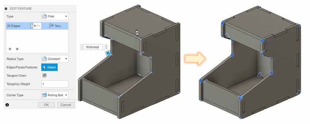
fillet. The fillet radius is set as same as thethickness/4parameter.
Export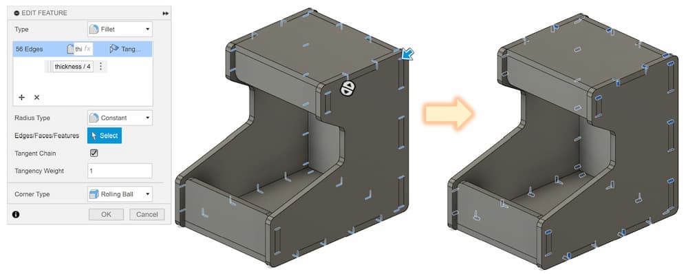
When export the outline of a plant, avoid export the original draft line, as it contain extra useless lines, and maybe be lines that are overlap (I).
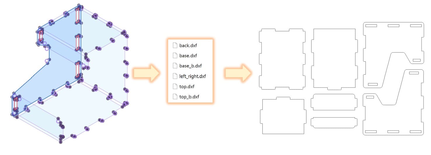
We can project the plant with a new sketch, the new one will be more clear and also have the fillet corners.Export the surface outlines of all parts. Each surface will be a dxf file. Then combine and arrange their angle and position in CorelDraw.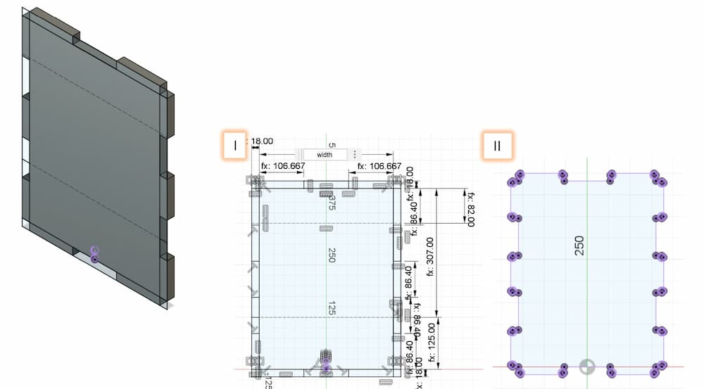
Staff - CorelDraw
Design Process
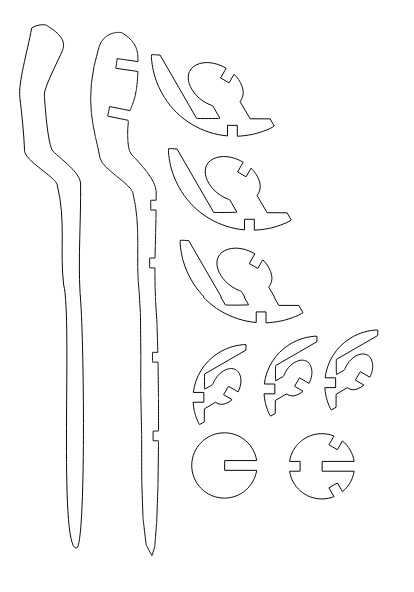
The main staff parts:
To build the staff, first I use the 'Freehand' tool to build a draft sharp, and use the 'Edit Shape Tools' to make the sharp more formal.The FABLAB elements: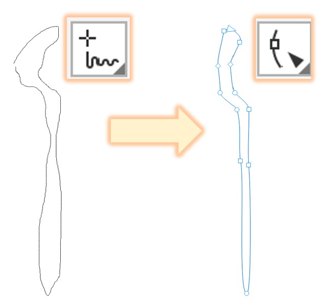
For the decoration, I track the online of the FABLAB logo with 'Outline Trace' tool, and cut it with rectangle to create the connection parts.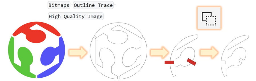
Finally, adjust the angle and position of the parts and combine the two files into one.
-
Testing in small size
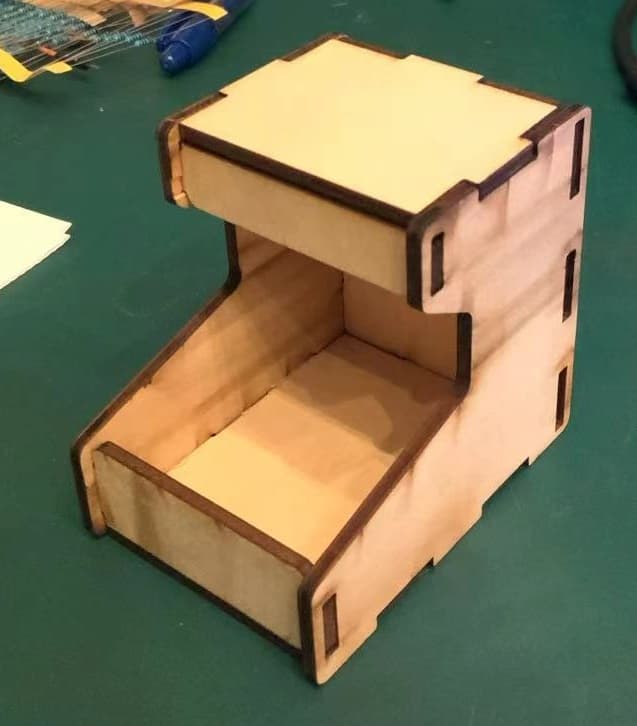
Before using CNC to produce the big model, I scale the size of the desgin and using laser cutting to build a small one, to confirm the design and the sizes are correct.
The orginal thickness of the high density fiberboard is 18mm, and I will use 2.83mm thickness wood board to build a small model. According to the thickness in week 3 assignment, the perfect thickness should be set to 2.6mm, so I scale the size to about 1:6.92.
Here are the result:
-
Adjustment
The cutter we use is the 8mm wood milling bit.There will be a problem when using round mill, as the round end mill cannot reach the right-angles corners, both right-angles corner will not be processed.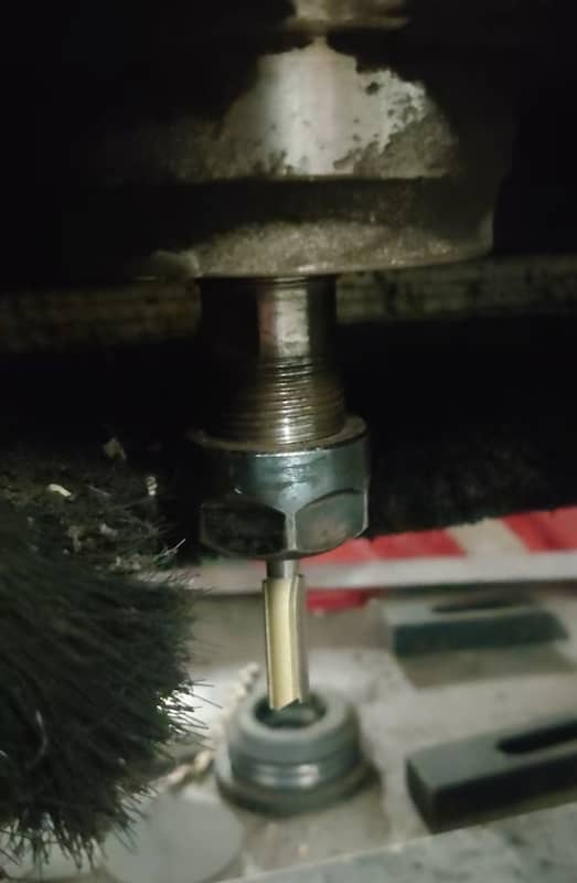
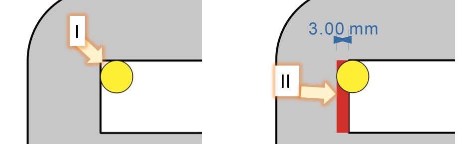
I. The milling bit can’t reach the right-angle corner
II. To solve this, we need to enlarge the right angle hole about 3mm moreHere is the adjusted dxf, black line is the orginal and the red line the adjusted one.
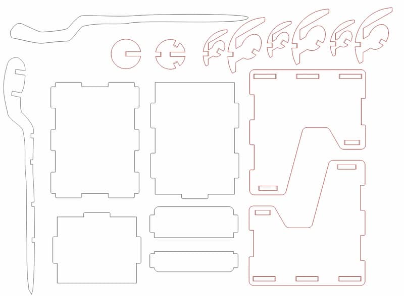
I. Both the close holes and thin concave connection part need to be enlarged.
II. For concave connection joints which is wide and open end, it can be sanded by smooth flat file later, so no adjustment is needed.After all concave connection part is adjust, the dxf file is ready for the CNC machine.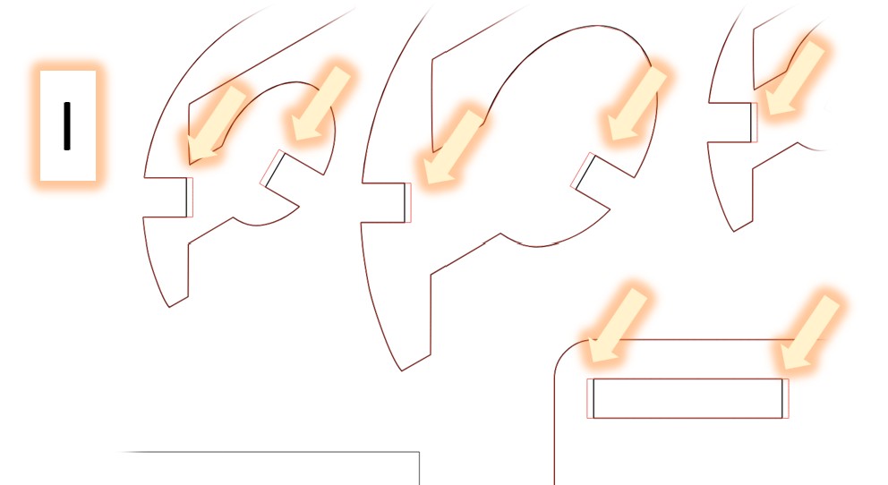
-
Machining
For detail setting, check the group assignment.
In simple, the setting process can be divided into following steps: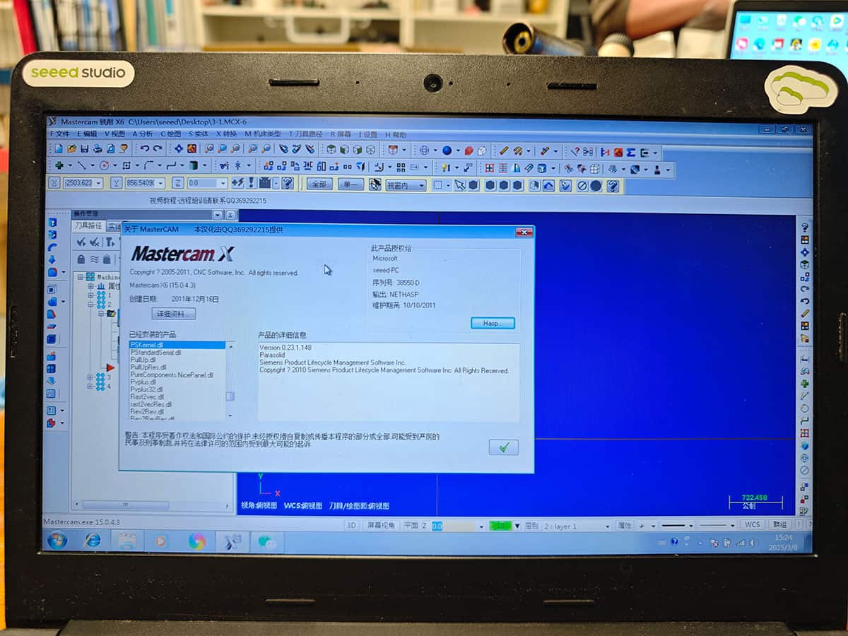
CAM Process
The main purpose of this step is converting the DXF files to
G-Code, which is a language for the machine to read. The software we used is: MasterCAM X6
1. Confirm the cutting method
As the sharp of all the parts we cut this time are prism form, the cutting method is contour milling. 2. Confirm the cutting tool
The cutter we use is the 8mm wood milling bit.3. Confirm the cutting order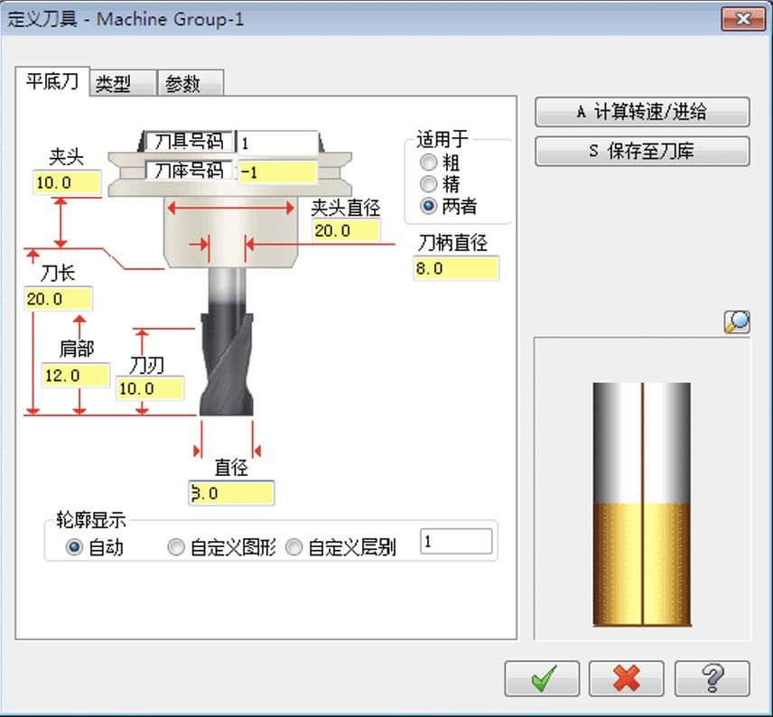
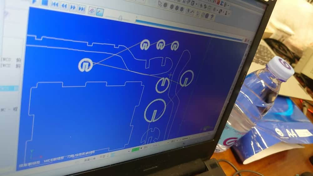
The lines in the dxf can be classify as outline and holes. Holes should be process first, as when the ouline be cut, the board with have to connection to the main board a floating around, course the hole position be crooked.
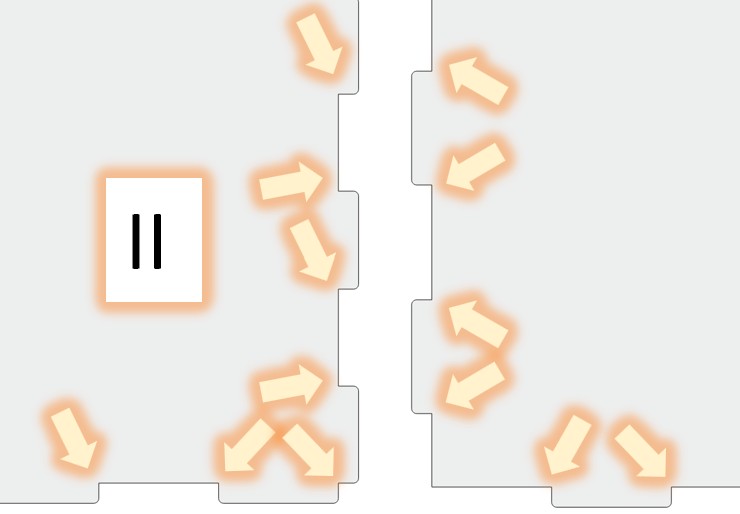
4. Confirm the cutting path direction
For example in the left one, the cutting path is outside of the edge, which is situable for a outline cutiing. The cutting path of the right one is inside the edge, which is situable for a hole cutiing, and become a wrong setting in this case.5. Confirm the cutting simulation After all setting are ready, simulate the cutting path and make sure anything go well.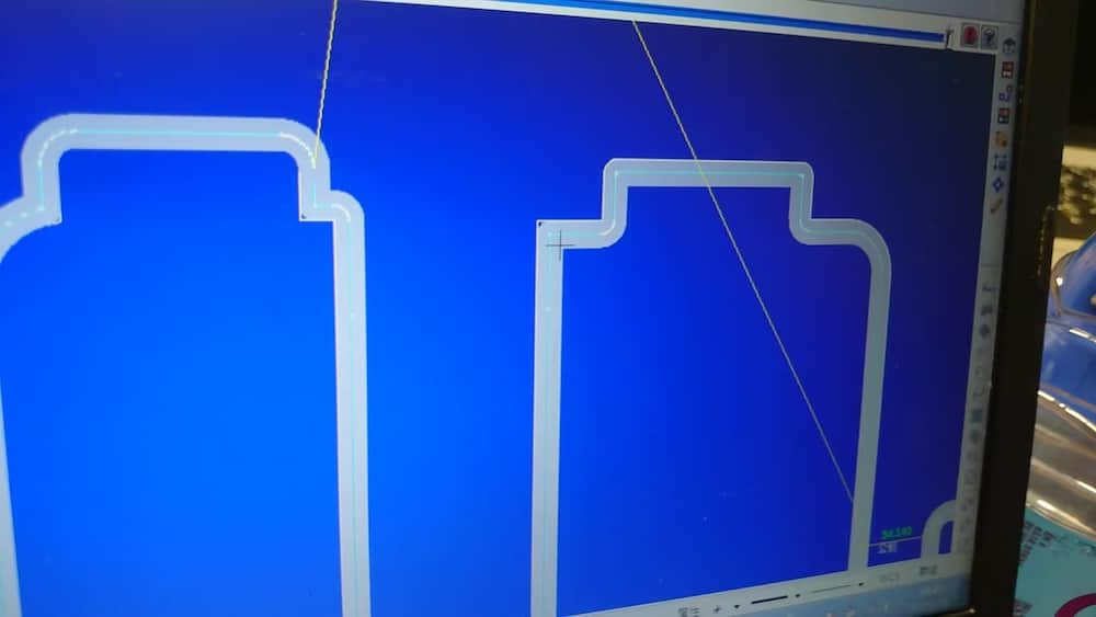
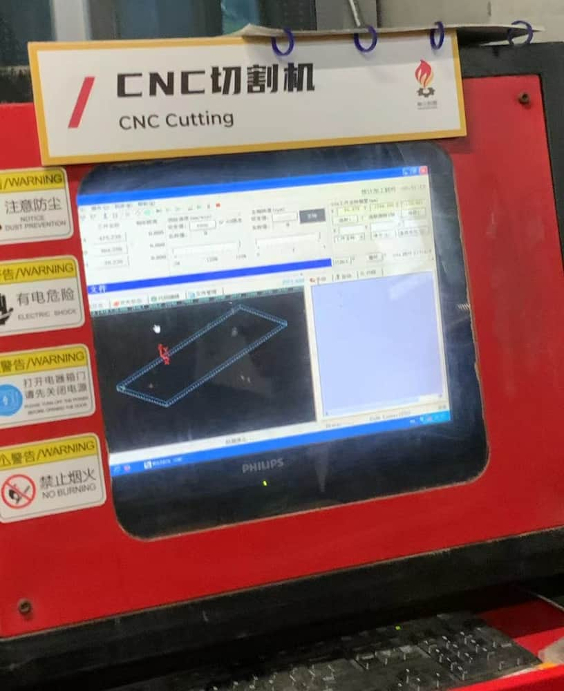
Hardware setting
1. Put the CAM file into the CNC computer After the g-code file is put into the computer, do the simulation to confirm everything is OK.
2. Install the material and verify the XY-axis orginal point
After the high density fiberboard is installed, use the 6 clamps around to fix it.3. Install the cutting tool and verify the Z-axis orginal point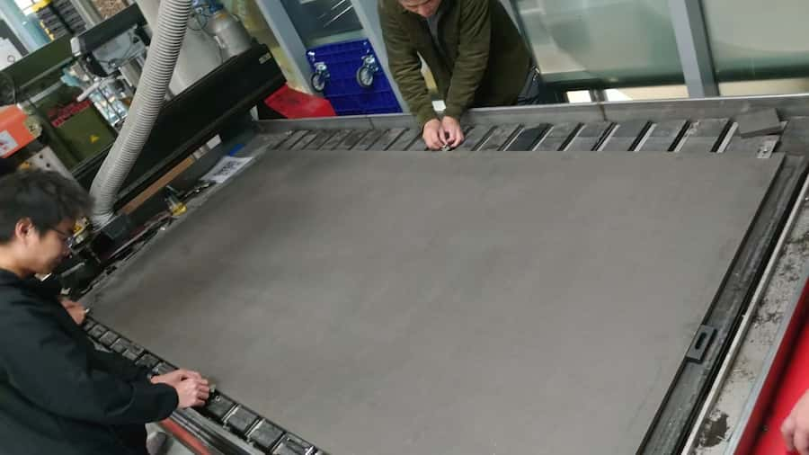
The tool is very sharp, safety gloves should also be worn!4. Make sure the satefy instruction before start cutting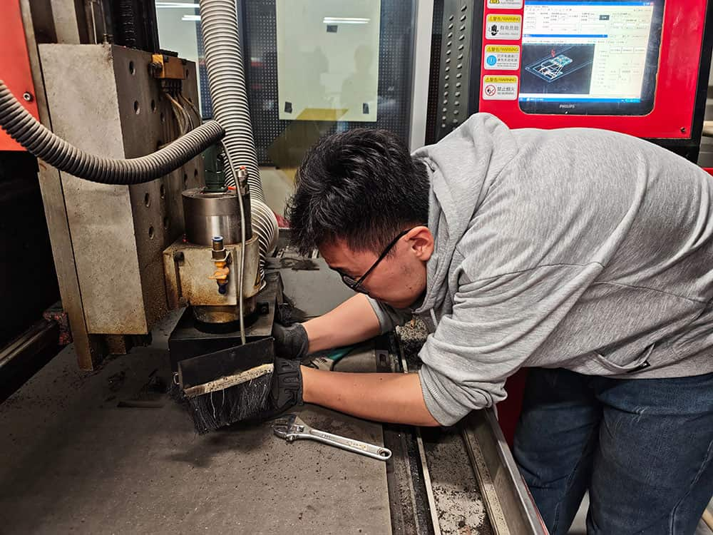
Don't forget to:
-Confirm the location of the emergency stop button
-Open the air dust processor
-Make sure the working area is clear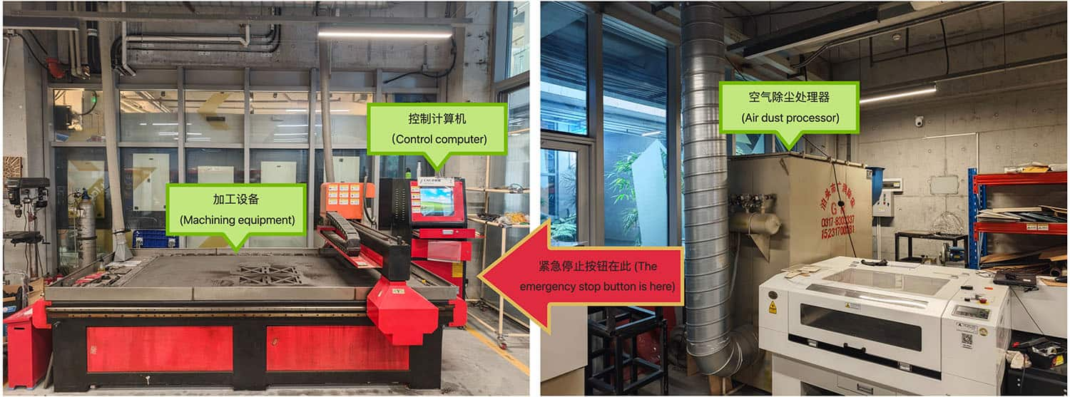
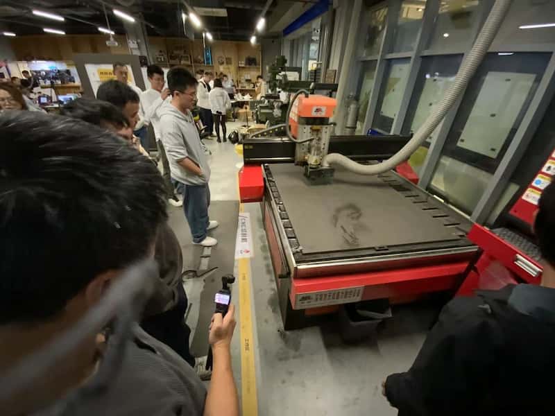
 warning
When the machine is processing, make sure to keep the satefy distance(Don't cross the yellow on the ground)!
Due to the large amount of dust and noise generated during CNC processing, safety goggles , noise-cancelling headphones and masks must be worn.
Also, avoid cut by the sharp edge of the material, safety gloves should also be worn.
-
Assumble
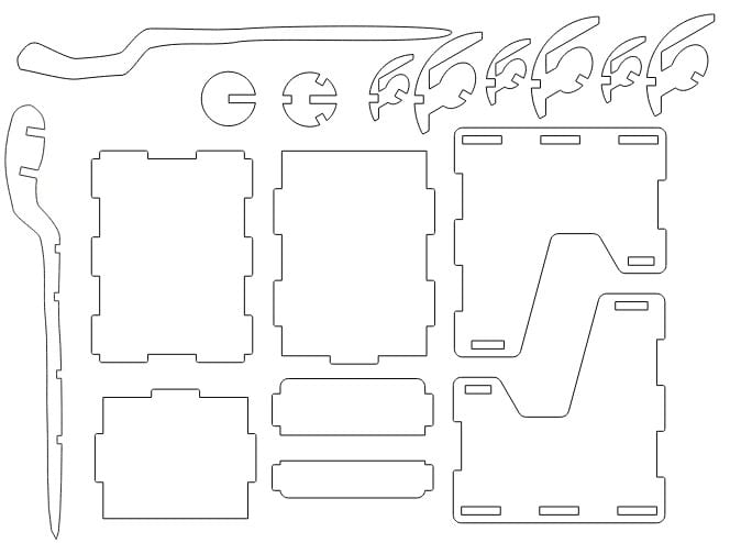
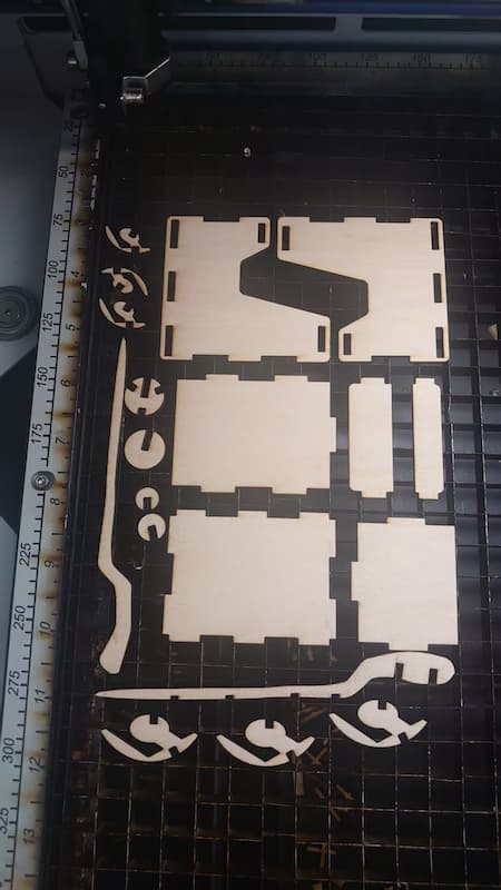
Here are the parts after cutting:
 The game shell
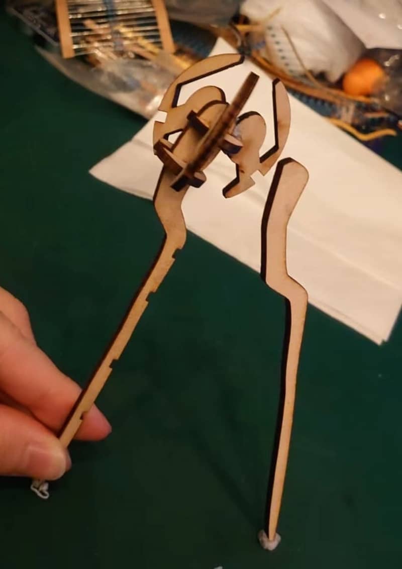 The magic staff
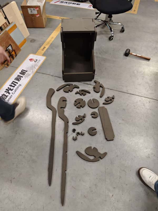
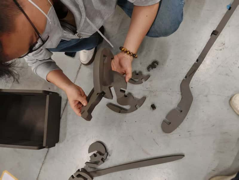
Result
Here are the final models:
No glue connection
The complete model of the game shell, connected without glue
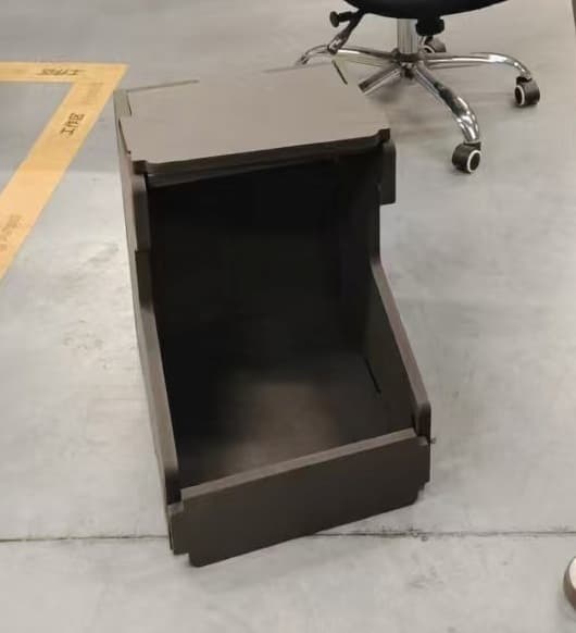 The game shell
Curved surfaces
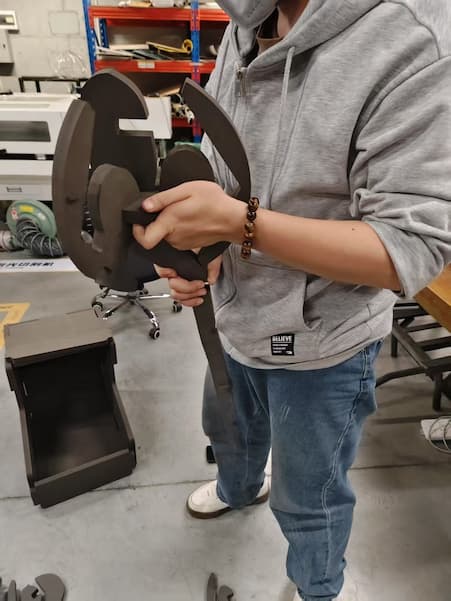
And the magic staff is also connected without glue, also with curved surfaces!
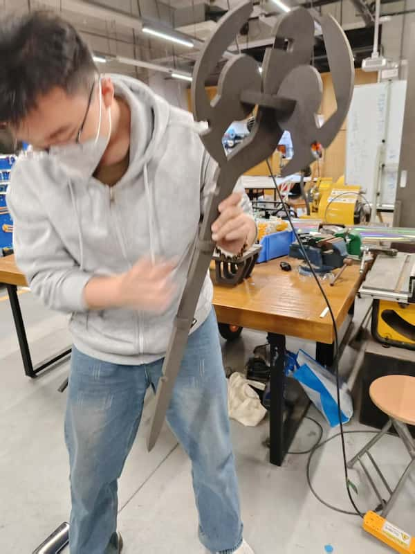 The magic staff