Week 7 Group Assignment: CNC Cutting
On March 8, 2025, members of the Chaihuo group arrived at the Chaihuo Maker Space to prepare for CNC cutting machine training and individual assignment cutting. However, that day Chaihuo Maker Space was simultaneously hosting the 48-hour "Exploring the Future of Embodied Intelligence: 2025 Seeed Embodied AI Hackathon," so the venue was crowded, making it impossible for us to start cutting (due to the significant noise), and we were informed that we could only begin after 8 PM. Therefore, we started with training and various preparatory work. Our instructor Matthew Yu invited Mr. Xu Guoqun (referred to as Engineer Xu below), an experienced structural engineer from Seeed Technology, to serve as our technical guide.
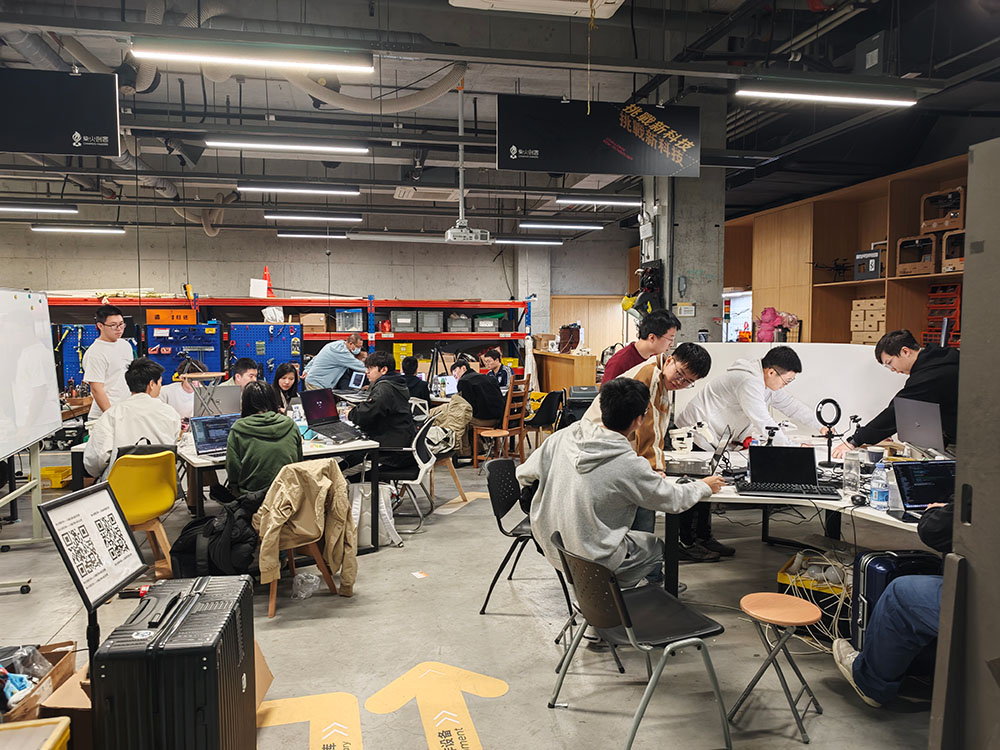
The Chaihuo Maker Space was full of participants for the 2025 Seeed Embodied AI Hackathon this weekend
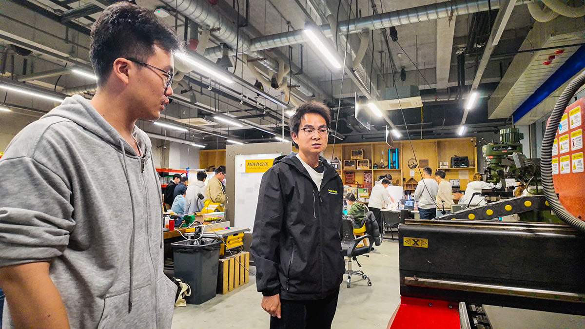
Instructor Matthew Yu (left) with Mr. Xu Guoqun, an experienced structural engineer from Seeed Technology (right)
Safety Training
Before using the CNC cutting machine, we received comprehensive safety training, learning about the machine's basic components and safe operating procedures:
- CNC Machine Components: Our CNC cutting machine consists of three main parts: the control computer, the processing equipment, and the air dust processor.
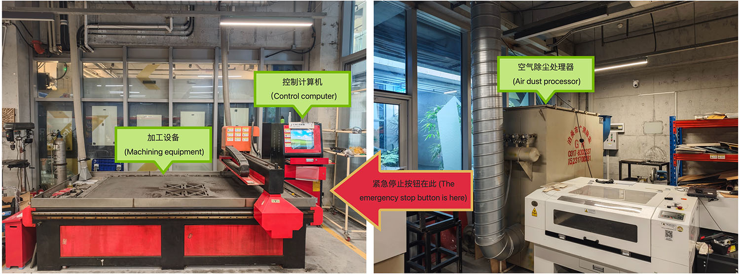
The three main components of the large CNC equipment at Chaihuo Maker Space and the location of the emergency stop button
- Cutting Tool Selection: We used an 8mm wood milling bit, but it's important to note that tool quality affects cutting results. Before operation, we need to check and secure the tool to prevent accidents during processing.
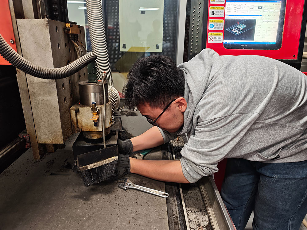
Matthew installing and checking the cutter head
-
Dust Prevention Measures: Since our equipment is located in an urban area, we must use exhaust and dust collection equipment according to municipal air emission requirements. Additionally, the work surface needs to be cleaned with a vacuum cleaner before and after each operation to ensure a clean working environment.
-
Electrical Hazards: During machine operation, it is forbidden to touch the operating surface with hands to avoid injury from tools or splashing objects.
-
Emergency Stop Button: When using such a large machine, everyone needs to know the location of the emergency stop button for immediate stopping in emergencies. Engineer Xu informed us that the emergency stop button is located on the right side of the control computer cabinet, as shown below.
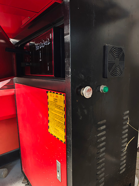
The emergency stop button is located here

From the sign in the image, I extracted and revised the following safety precautions:
Attention
- You are not allowed to operate this machine before training qualified.
- The operator should put on the appropriate working clothes, don't wear the gloves or other ornaments.
- Machine bearer feet must earth the ground and don't take any safety devices down.
- Before starting machine, inspecting Rails as well as Rack and pinion carefully, if there are obstacles, cleaning up without delay. And the object we are working on must be fixed well.
- While working, the cutting tool must be truly locked well and attention the direction of rotation. Don't use the bits which distorted or damaged.
- In the machine operation, the staff shouldn't leave. Don't approach or touch the working spare parts.
- Please do not adjust or repair the machine before the power is off.
- After the work finished, clean the machine carefully and lubricate components.
- Protective Measures: Due to the large amount of dust and noise generated during CNC processing, safety goggles and noise-cancelling headphones must be worn. Also, when cutting wood boards and materials that generate a lot of dust, masks must be worn.
CNC Cutting Machine Specifications and Setup
Equipment Specifications
The main specifications of our lab's CNC cutting machine are as follows:
| Specification | Details |
|---|---|
| Manufacturer | Tiancheng Xinli CNC |
| Model | 3STX-1325A |
| Workbench Size | 1450mm × 2900mm |
| Processing Range | 1300mm × 2500mm |
| Z-axis Travel | 180mm |
| Feed Height | 200mm |
| Positioning Accuracy | ±0.15/300/mm |
| Spindle Speed | 0~24000 (r/min) |
| Engraving Commands | G Code, UPP, mmg, nc |
| Idle Speed | 0~20000mm/minute |
| Processing Speed | 0~15000/minute |
| Resolution | 0.00625/pulse |
| Tool Diameter | 3.175mm, 4mm, 6mm, 8mm, 10mm, 12.7mm |
| Spindle Power | 3KW water-cooled |
| Cooling System | Water pump |
| Actual Weight | 2200kg |
| Machine Power | 380V 50Hz (built-in switching power supply) |
Setting Up the Cutting Machine
- Checking and Cleaning the Table Surface: Before using the equipment, we need to carefully clean the table, first removing debris, wood blocks, and other hard objects that might affect the flatness of the board, then vacuuming the table surface to remove sawdust and small debris.
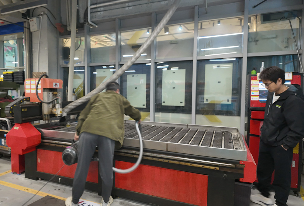
Carefully cleaning the cutting machine table with a vacuum cleaner
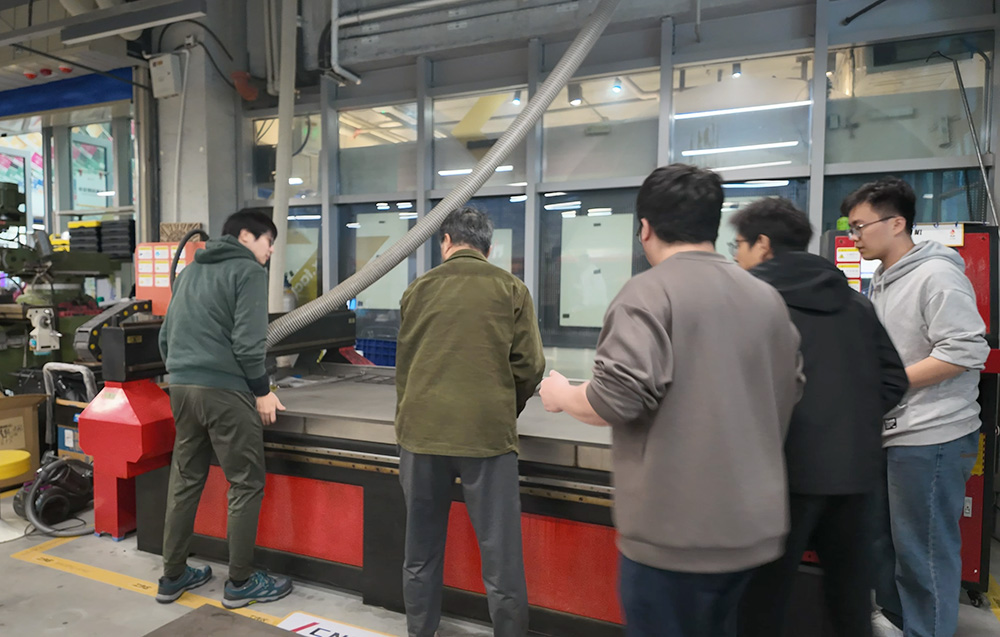
The 1.5*2.4m, 1.8cm thick high-density fiberboard is much heavier than imagined, requiring multiple people to lift it onto the table
- Securing the Processing Material: For this CNC cutting, we used high-density fiberboard (HDF). Due to the limited processing size of each CNC machine, we needed to place the test processing material flat on the processing surface. The board is black-gray, very heavy, requiring 2-3 people to lift. It's best to keep the processing material parallel with the machine's processing direction. Then use bolt fasteners to secure the board, ensuring the metal fastening strips don't intrude too much into the board area.
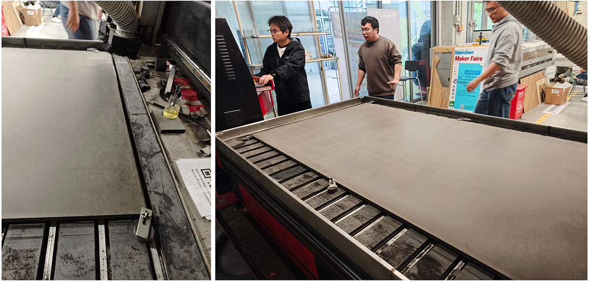
Securing the board at various corners with fasteners, avoiding metal fasteners intruding too much into the board area
- Setting the Processing Origin: Before each processing, we need to check the machine's processing origin and simultaneously check the processing origin set in the processing file. The processing origin contains data for all three axes.
Note: Since our lab's CNC machine had not been used for a long time, the Y-axis limit sensor on the machine bed guide rail had failed, preventing us from using the machine's own zero-point setting tool. We could only manually set and adjust the machine's zero point to ensure the processing dimensions meet our requirements. Special attention to safety is needed at this time.
- G-code Modification: Because our machine doesn't support "automatic return to origin," we need to delete the "automatic return to origin" code from the G-code.
- Speed Modification: Adjust cutting speed according to material characteristics and tool conditions.
- Machine Control Keys:
- F8 - Generate simulated CAM path
- F9 - Start cutting
- F10 - Pause
- F11 - Stop
- Workspace Parameters:
- Board size: 2440mm × 1220mm
- Processable area: 2400mm × 1200mm
Converting DXF Files to G-Code
Engineer Xu guided us on how to use MasterCAM X6 software to convert designed DXF files into G-code. This process was performed on an old Lenovo laptop running Windows 7 that came with the CNC machine. This is a powerful CAD/CAM software mainly used for designing parts and programming CNC machines for manufacturing.
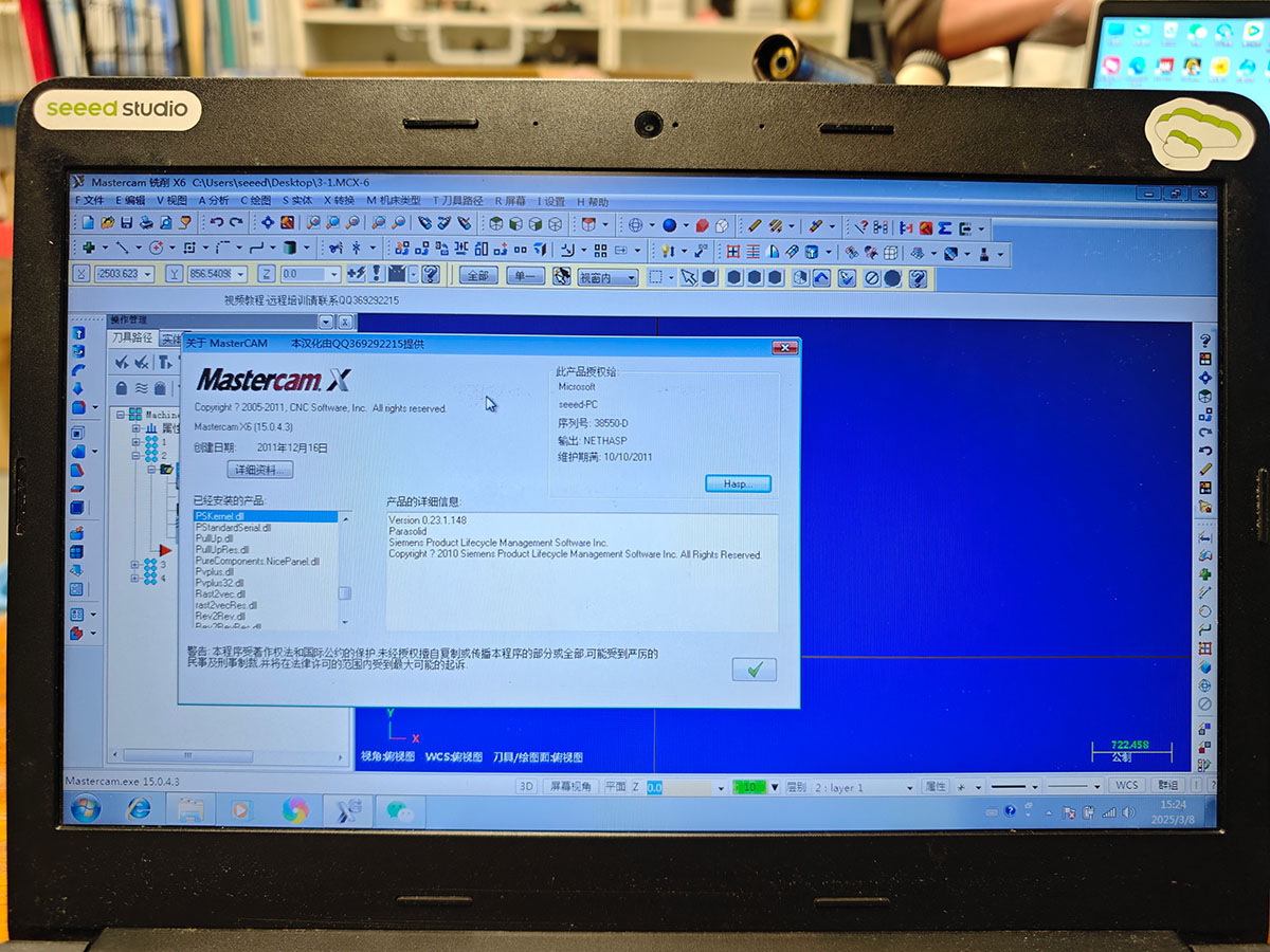
MasterCAM X6 software
MasterCAM Parameter Settings
Engineer Xu Guoqun explained the following parameter settings in detail:
-
Cutting Method Settings:
- Contour milling
- 2D slotting
- Surface milling
- Slot milling
-
Tool Parameter Settings:
- Tool name: Custom
- Tool number: 1
- Tool diameter: 8mm
- Corner radius: 0
- Length: 10mm
- Number of flutes: 4
- Type: Flat end mill
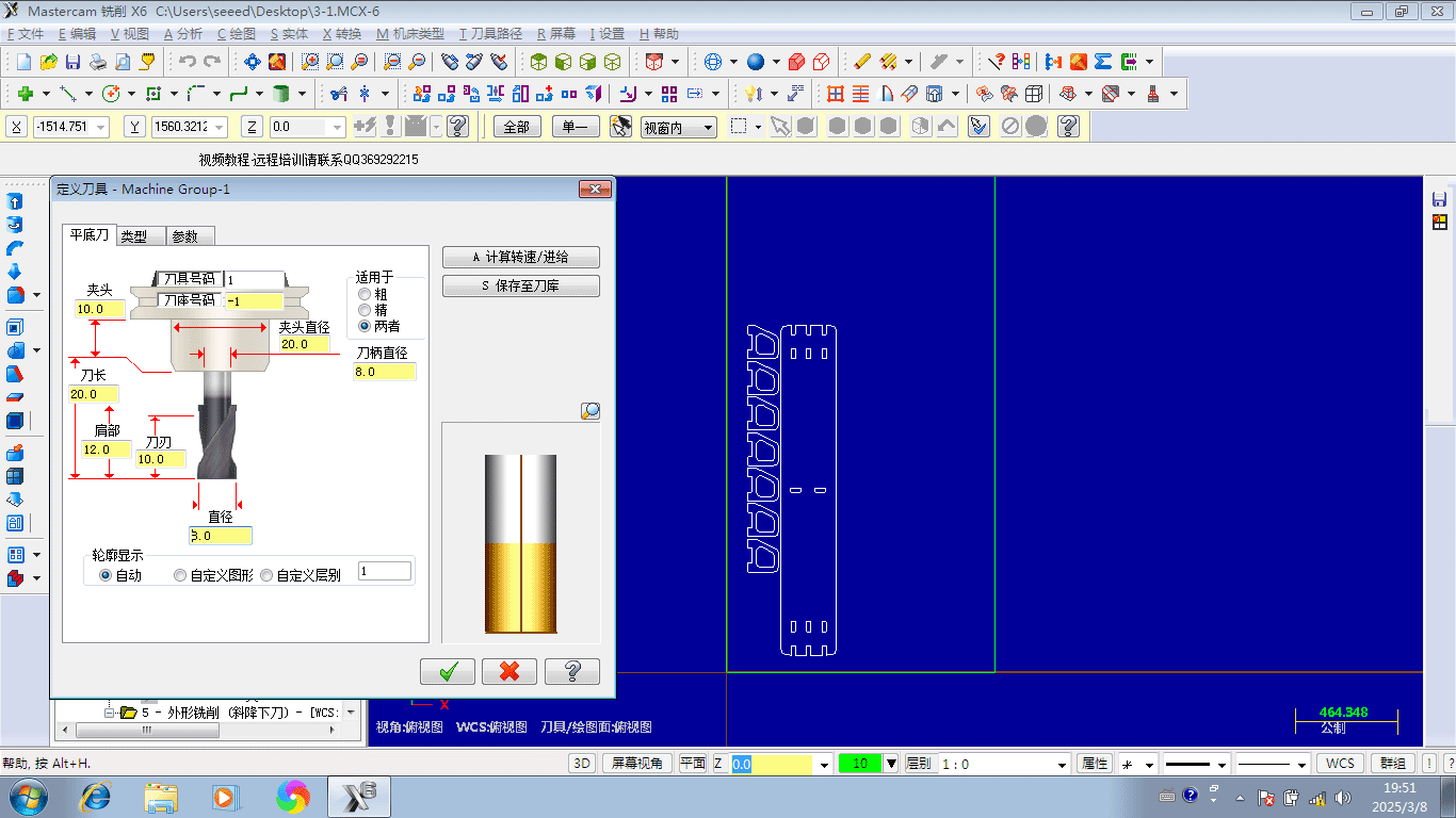
Defining the tool in MasterCAM X6, we used an 8mm diameter flat-bottom cutter
- Spindle Parameter Settings:
- Spindle direction: Clockwise
- Feed rate: 5000
- Spindle speed: 15000rpm
- Cutting speed: 500mm/min
- FPT: 0.0833
- CS: 377.0028
- Cutting Parameter Settings:
- Contour milling method: 2D
- Correction method: Computer
- Correction direction: Right
- Calibration position: Tool tip
- Maximum processing depth: 0.05mm
- Allowance Settings:
- Wall allowance: -0.1mm (Special note: Engineer Xu Guoqun particularly reminded us that for inlaid inner holes, the hole width needs to be increased by 3mm on both sides, otherwise the board material cannot be inserted)
- Bottom allowance: 0mm
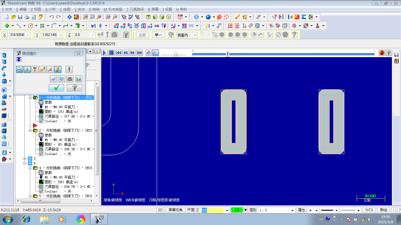
When the tool cuts inner holes that need to be inlaid with board material, because the cutter head rotates, the designed square corners of the inner holes will become rounded after cutting, requiring additional allowance to enable successful insertion of the board material
- General Parameter Settings:
- Origin/Reference point: X, Y, Z axis origins of the machine bed; tool position and coordinates
- Arc filter/tolerance settings: Overall error 0.025mm
- Minimum arc radius: 0.2mm
- Maximum arc radius: 10000mm
G-code Generation Steps
Engineer Xu Guoqun demonstrated the complete process of G-code generation:
- Checking and Repairing CAD Design Files: First, we need to check that the processing line segments in the generated DXF/STEP files are continuous, without breakpoints. Otherwise, we need to repair the file and complete the breakpoints.
- Layout of Processing Design Files: There were 4 people in our group total. Except for my design, which took up relatively little board space, the files of the other 3 members all required an entire board, so the team's individual designs were arranged on 4 boards, in 4 files. We chose a 1.2*2.4m, 18.0-18.5mm thick black high-density wood board (with slight thickness variations) as the processing material. The layout process is time-consuming and requires rich experience. Experienced Engineer Xu helped us complete this step.
- Setting the Drawing Zero Point: After completing the layout, we need to set the processing zero point. Because our machine's processing zero point is in the lower left corner, we need to ensure that the processing range can cover the entire board area, while also testing the installation and positioning of the board.
- Setting the Workpiece Processing Order: Import the files to be processed and arrange them in order. Since the processed board size is 1200mm×2400mm, it is recommended to draw a border first for positioning and placing workpieces. When arranging the processing order, we follow the principle of "inside before outside, small before large." "Inside before outside" means processing the inner holes of the workpiece that need to be emptied first, i.e., cutting all small holes on the entire board first, then cutting the outer contours from small to large. The main purpose of this arrangement is to avoid cutting large parts first, causing them to lose fixed support, and subsequently causing position deviation and inaccurate processing when cutting small inner holes, as the workpiece cannot be firmly fixed. A reasonable processing order ensures that each part maintains precise positioning until all necessary internal cutting work is completed.
- Previewing the Tool Path: After setting the processing order, we can generate the tool path. At this point, we can see on the image that our workpieces are processed in the order we arranged, from the first workpiece to the last, and we can clearly see the starting point and travel path of the tool being processed.
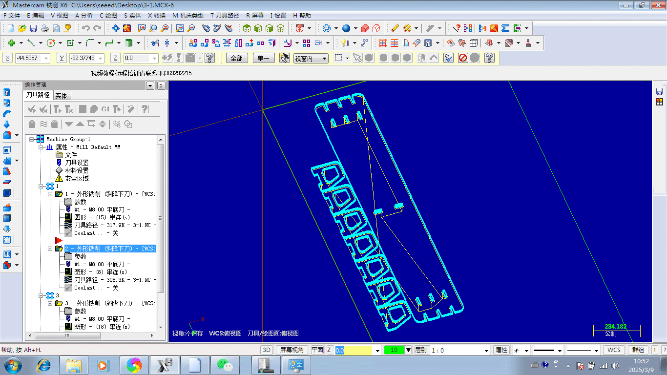
Previewing the cutting path in MasterCAM X6 software
During the cutting process, pressing the F8 key also allows you to view the tool path, as shown below.
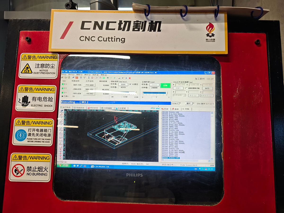
During the cutting process, pressing the F8 key displays the tool path
-
Final Confirmation Step: The most important step is to zoom in on the pattern to see that our tool path must surround the periphery of the workpiece being processed, as the tool path is based on the center axis of the tool.
-
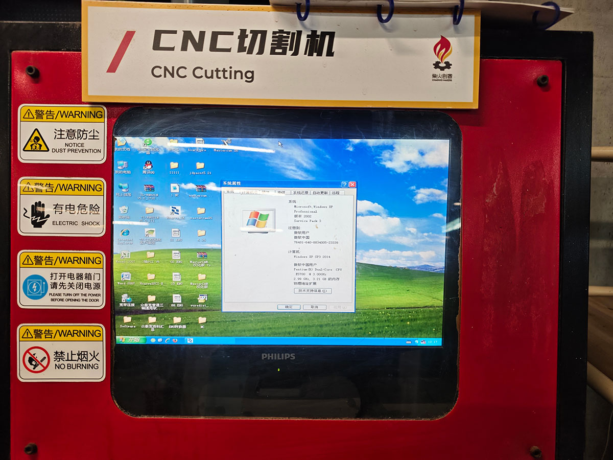
Generating G-code: After confirming everything is correct, generate the final G-code file. The final G-code is copied to a USB drive, then transferred to the CNC cutting machine's control computer. That was an even older Windows XP computer.
Cutting Precautions
At 8 PM, we were finally allowed to turn on the cutting machine. The enormous noise made us keep our distance.
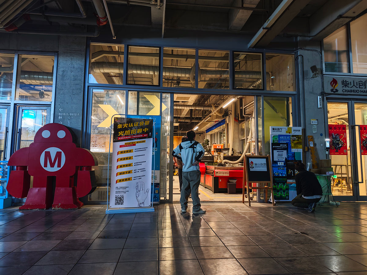
The loud noise of the CNC cutting machine at work is impressive
Based on Engineer Xu Guoqun's guidance and our practical experience, there are several important precautions:
- Processing Rules: CNC machines can only process external right angles, not internal right angles. This is unavoidable due to the processing principle. Therefore, when designing, avoid designing internal right angles or drilling and cutting internal right angles.
- Inner Hole Size Adjustment: For inner holes that need to be inlaid, Engineer Xu Guoqun especially emphasized that the hole width needs to be increased by 3mm on both sides, otherwise the board material cannot be inserted.
- Processing Errors: CNC processing errors are relatively small. When our designed processing width was 18.5mm, the final processed product was almost 18.1mm. This error is within the acceptable range of our design.
- Tool Quality: We experienced unexpected issues during cutting – the newly purchased 8mm tool was too soft and kept breaking. Instructor Matthew changed tools 3 times until the 4th attempt using an old tool finally succeeded in cutting smoothly. This reminds us of the importance of tool quality for processing results.
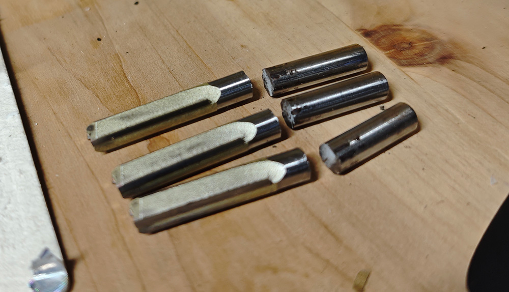
The broken cutter head during cutting. We suspect the purchased cutter was suitable for cutting wood but not for higher-density boards
- Control and Intervention During Processing: Engineer Xu required us to carefully observe during the cutting process and press F10 to pause promptly in case of unexpected situations. Besides accidents like broken needles, it's best to press the pause button promptly when cutting parts that need to be excavated, when the excavated part is about to separate from the main body, raise the cutter head and remove it, reducing the chance of accidents caused by these already unfixed structures being cut again.
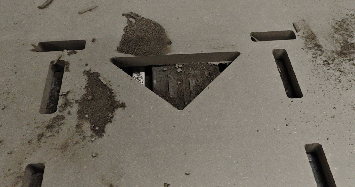
Movable parts produced during the cutting process should be removed promptly
Group Results Showcase
After several hours, around 1 AM, we finally completed all the assignment cutting work

The first completed cut was Hongtai Liu's bookshelf. Looking at the tools scattered on the floor, we knew assembly wouldn't be easy, mainly because fine tolerances made structures requiring numerous connections difficult to assemble, but it was eventually assembled
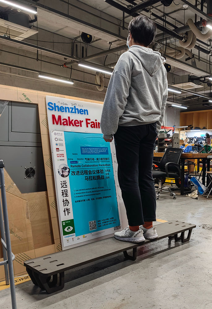
My cut monitor stand has a simple structure, making it easy to assemble. I tested its support capability, and it's very sturdy
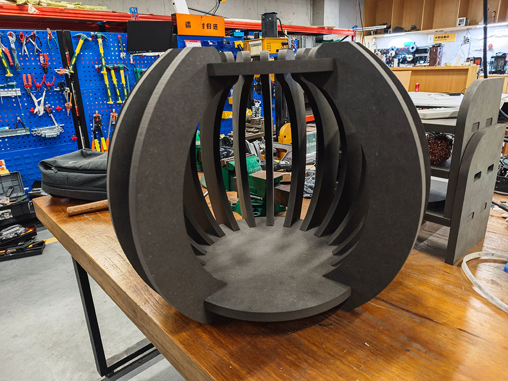
Chon Kit Kuok's cat house was also easy to assemble. It looks great, but we don't know if cats will like it
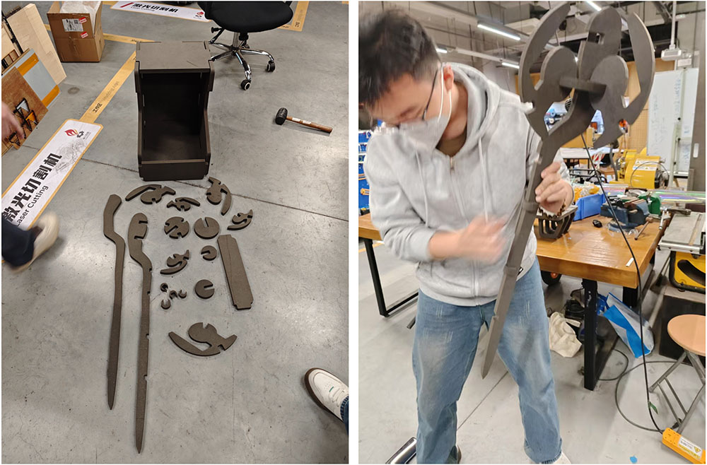
Long Wai Chan's work had complex parts. At first, we couldn't figure out what these strange parts were, but later found out they were magic wands!