3D Print
The assignment of the week is to design and 3D print an object that could not be made subtractively.
My idea is to design a one-piece molding parts. One-piece molding in 3D printing refers to the process of creating an entire object as a single, continuous piece rather than assembling multiple parts, which can't be made subtractively.
Draft Design
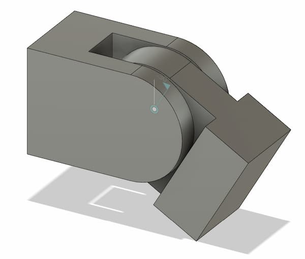
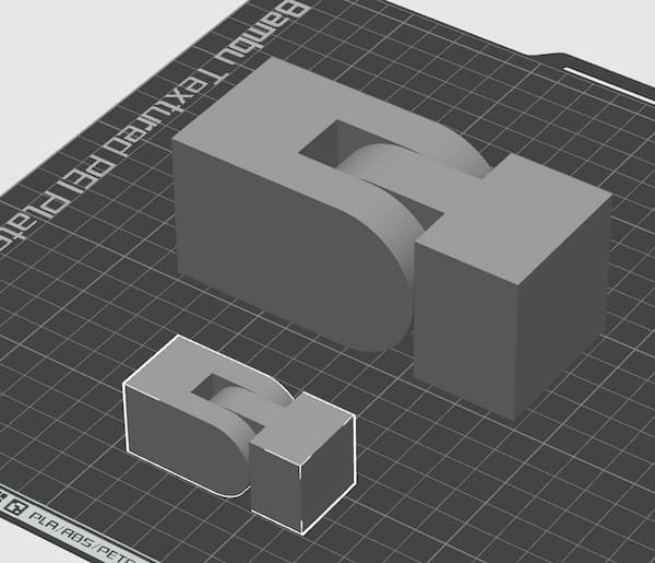
My first idea is to design a one-piece joint component like this:
Design in fusion360
Design process
First start the design from the sketch.
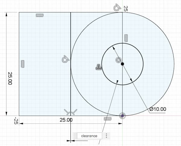
As I want the clearance be adjustable in the further design, I set it as parameter
clearance and set it as 0.5mm for draft.

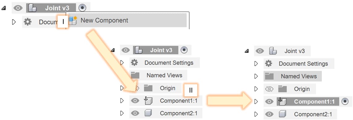
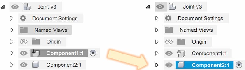
New Component.II. The following step will occurs inside component 1, so make sure you choose the component 1 by click it. There will be a dot on the right if you do it correctly.
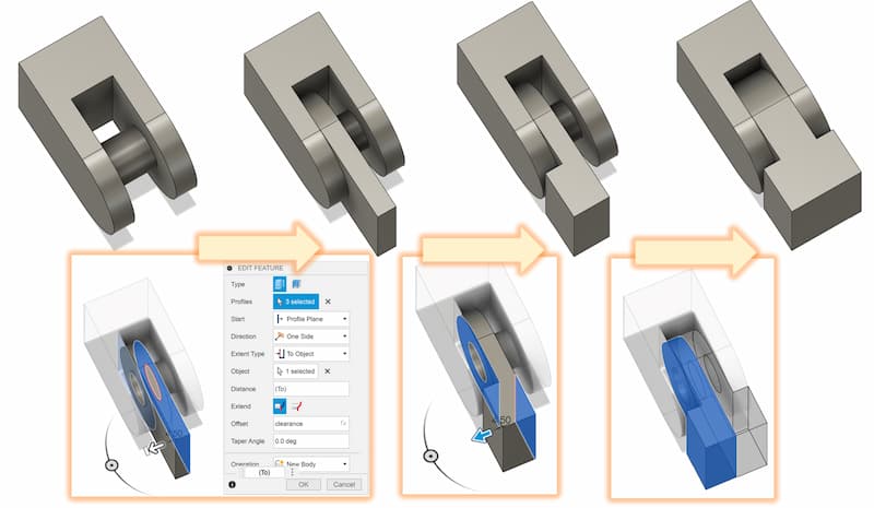
extrude to extrude the half body
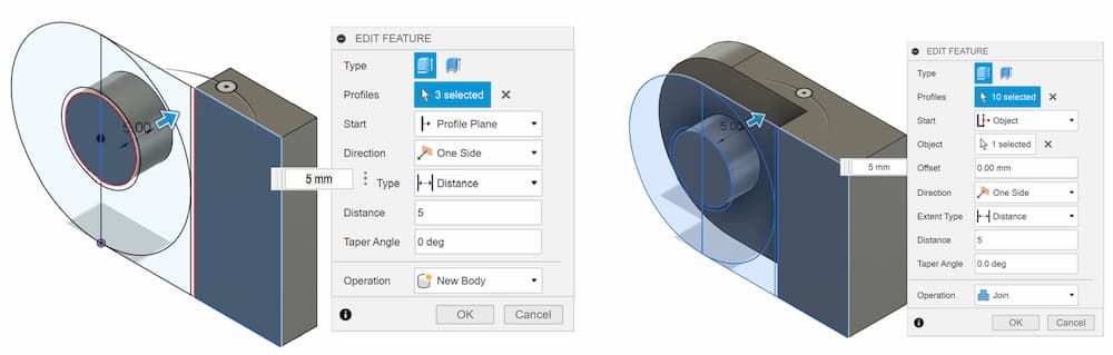
mirror to mirro the rest of the body. Now we finish the component 1.
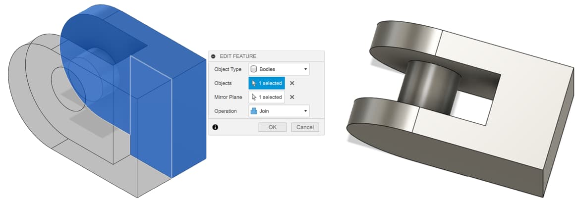
extrude and mirror to form the body of component 2.
3D Printing
After the stl file is generated from fusion360, the next step is print it out.
Print process
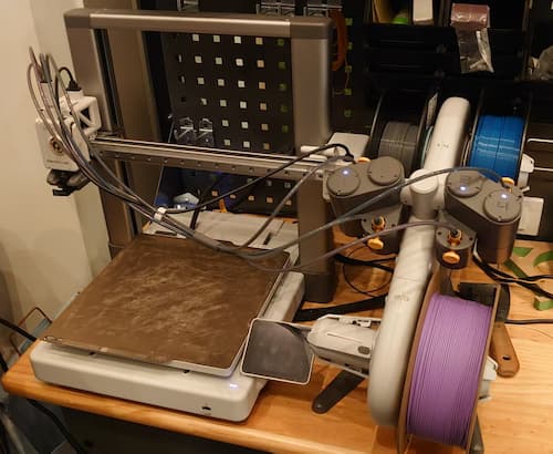
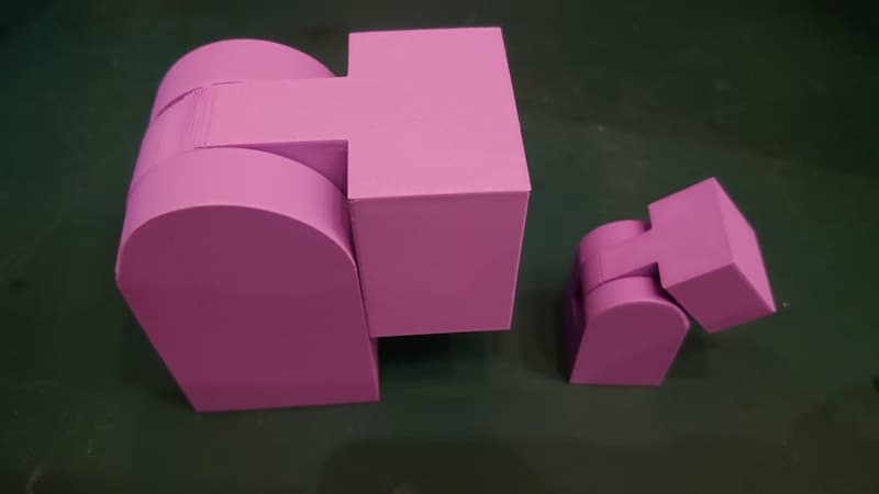
I use Bambu Lab A1 as the printing machine and use the BambuStudio as the slicer.
The result:
Advanced Design
From the draft design, both 0.5mm clearance and 0.25mm clearance are moveable, where 0.5mm clearance can't hold still in special angle but 0.25mm can.
So I want to test the limit of the clearance which can move freely or holding still.
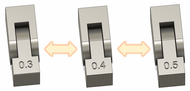
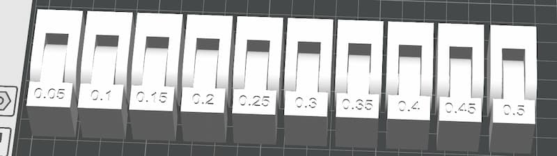
In order to achieve this goal, I want to print the same model from 0.05mm clearance to 0.5mm, test it with every 0.05mm step.
In order to classic the clearance of the model, I add a mark with the clearnce on the model.

Add-in: ParametricText
In Fusion 360, an "add-in" is a custom extension or plugin that enhances the software's functionality. These add-ins can automate repetitive tasks, introduce new tools, or integrate with other software and services.
One of them is ParametricText tool, which allow the text change with the parameter.
Download and Install add-in
Downloading the add-in
First we need to download the add-in from AUTODESK App Store.
Add-in: https://apps.autodesk.com/FUSION/en/Detail/Index?id=2114937992453312456
I. Remember to choose the operating system based on your computer
II. Click Download.
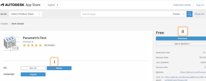
ParametricText_win64.msi.Installing the add-in
Detail instrustion of adding add-in
- Create a top level folder including the msi file with exactly same name, and paster the folder into the path:
C:\Users\...\AppData\Roaming\Autodesk\Autodesk Fusion 360\API\AddIns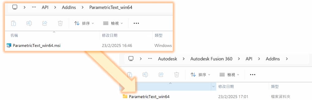
- Go back to fusion360, press hot key
sand searchScripts and Add-ins.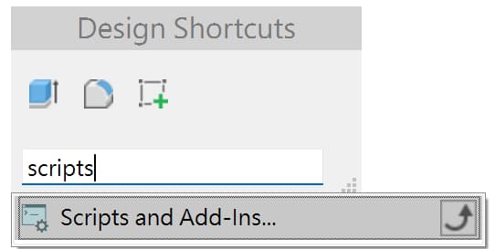
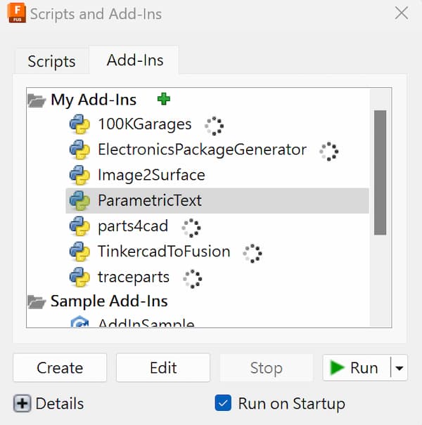
- Confirm the 'ParametricText' is installed.
Set the text as parameter
- Write a text in a sketch with 'Text'
- Search for the
Change Text Parameters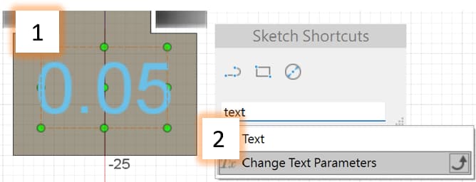
- Press the
+sign at the left bottom, it will create a new bar - click the text you want to set as parameter
- the bar name will change
- Enter the parameter you set.
For example, I first set a parameter call
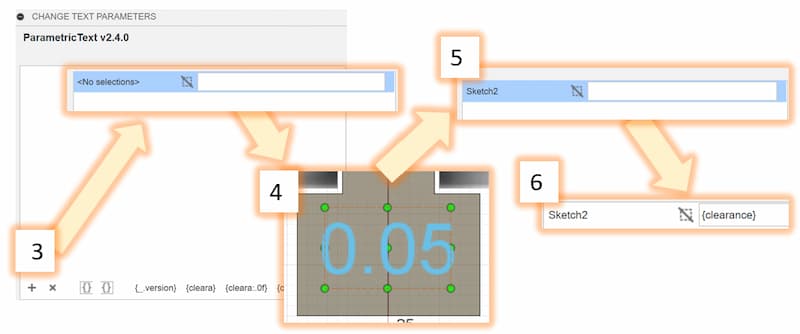
clearanceinchange parameters, so I will enter{clearance}in bar in6.above
Now the text will change as the dimension when you change the parameter.
3D Printing
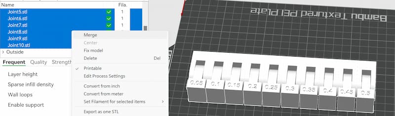
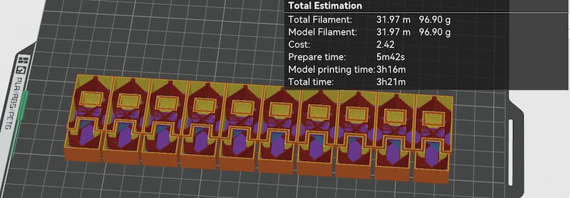
Download the stl form fusion 360, import them to the BambuStudio and slicer it!
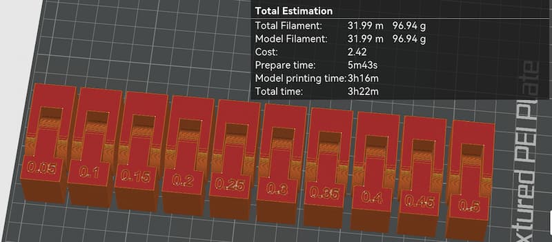
Place the parts as close as together can usually save printing time, but compare to the following setting, the printing time doesn;t reduce much.
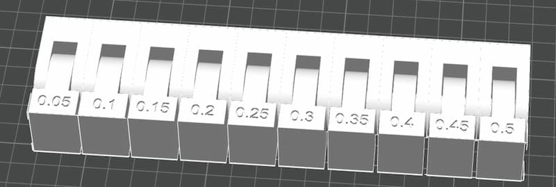

Merge.
The final result:
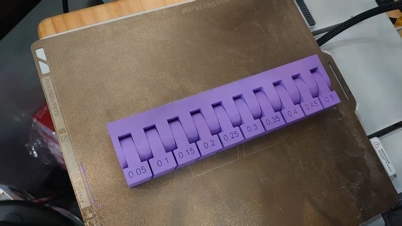
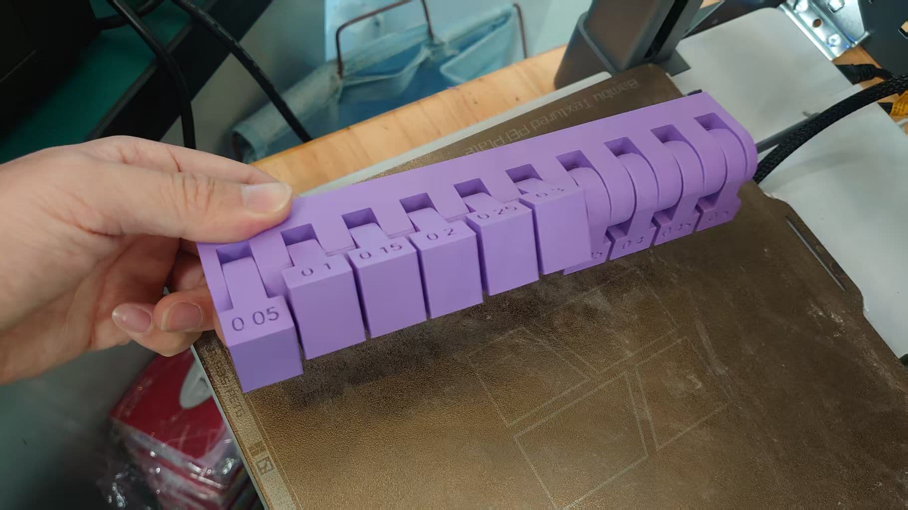
With 0.05mm clearance, the parts can't move
With 0.1~0.3mm clearance, the parts can move and the friction is strong to "hold" the parts
With clearance > 0.3mm, the parts can move freely and friction isn't strong enough to "hold" the parts.