System Integration
This weeks individual assignment:
- design and document the system integration for your final project
This weeks learnings:
This week, I've learned to appreciate clearly defined tasks and expectations even more. Otherwise, I've been able to bring together a lot of thoughts and ideas, some of which I'd already developed in previous weeks. Accordingly, this week's learning is quite manageable for me, which is certainly pleasant.
electronics
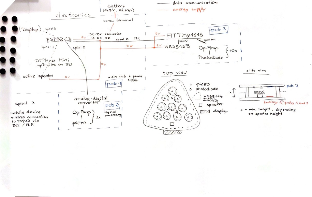
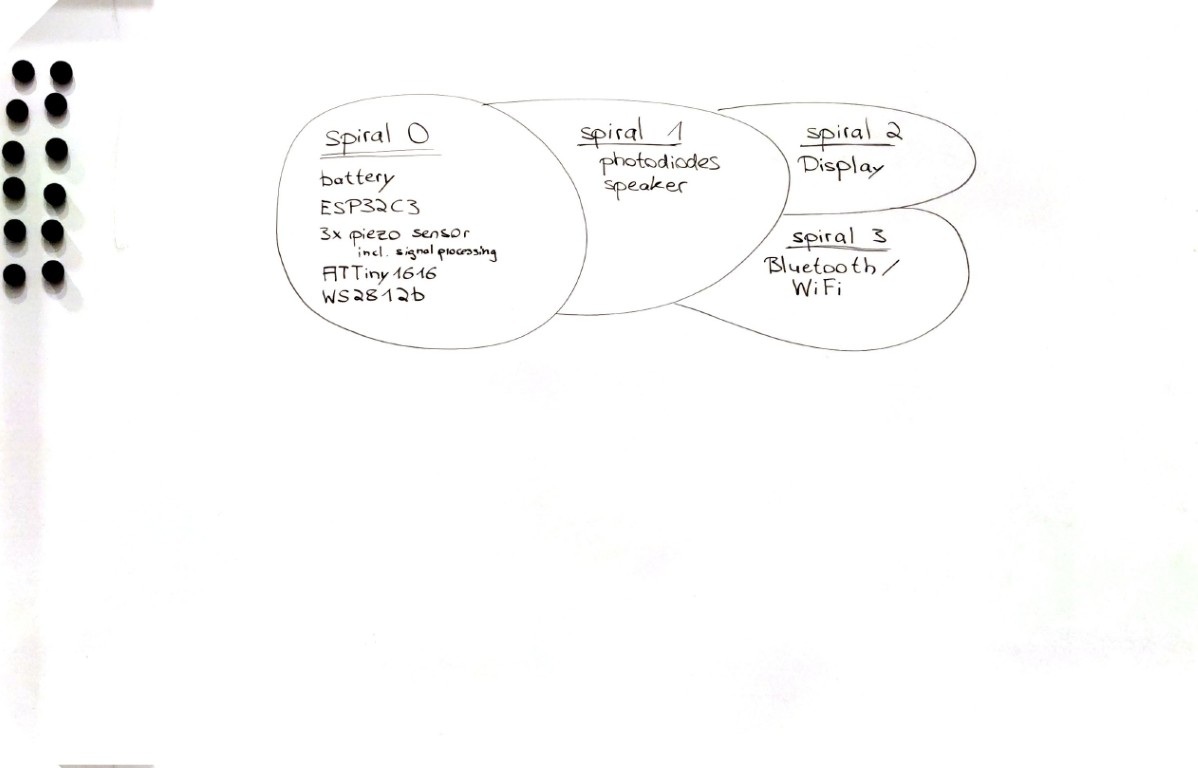
In the case of my final project, I find the electronics quite complex, as the final stage combines the mobile power supply, signal processing, wireless communication and control, and the wired communication of multiple microcontrollers. Therefore, this week I focused primarily on thinking through meaningful spirals in the spirit of spiral design.The easiest way to express my thoughts is probably through my wild whiteboard writing.
If we go further backwards, we end up at pcb2, which only handles signal processing of the AC voltages output by the piezo sensors and digitizes them, then passes them on via cable to the ESP32C3 or pcb1. Here, I have to absorb voltages that could damage pins. These are primarily the negative voltages that the piezos can output and voltages greater than 5 V. To do this, I have to scale the voltage range reached in the real application so that I can best represent it with the available 5 V. To do this, I have to finalize my setup next week and measure values. Based on this, I will dimension a suitable voltage divider with resistors. Since I will also need the negative half-wave and the zero crossings of my signal, I have to apply an additional +2.5 V as an offset. I may also use an operational amplifier here. I can absorb negative voltages with a Schottky diode; for voltages above 5 V, thanks to Digikey, I already own a suitable Zener diode. Nevertheless, this part is the one that's causing me the most headaches, partly because it's unclear how reliably I can detect what's happening above the board with my piezo sensors. Either way, this will be part of my Spiral 0, i.e., my defined list of requirements – I don't necessarily consider reliability a factor here.
PCB1 will be by far the most important and, above all, the one where most of the action happens. I'll use it to power all the components and, using the ESP32C3, bring together all the functionalities, including Bluetooth communication (spiral 3!). I already have the battery ready; it's designed for about four hours of operation with the 100 LEDs estimated there, based on the measured power consumption in the group assignment for the output week. Contrary to what I wrote on the whiteboard, a screw terminal wouldn't be compatible at all, because the connections for charging the battery are different. I still need to identify these and get a suitable socket for mounting them on the PCB. I also already have a DC-DC converter that can output up to 3 A at 5 V; that seems to be the maximum of what can be mapped onto a PCB. However, I don't want any additional power, so if in doubt, I'll also design and connect the LEDs so that I don't exceed 3 A (~40 mA per LED, depending on the light color/intensity). Another major consumer would be a speaker, and I've opted for an active speaker (Spiral 1), which should be ready for pickup tomorrow. Its size will determine the internal height of my construction or housing. Spiral 2 would also integrate a display, but I'm having trouble with this, given the application scenario and water resistance. Overall, I'm leaning toward a GUI rather than an app, which I'm currently considering for Spiral 3—but it could easily replace the display. Important information about my scribble: I've only drawn active components, of course; a full circuit would be too detailed here. However, initial plans for this already exist, and if all goes well, I'll mill it during Wildcard Week.
Also shown on the whiteboard are the locations where I would mount each component. The placement of the piezos can already be seen in some pictures in the documentation of my final. The photodiodes would be positioned centrally under the cups, possibly surrounded by LED rings. LEDs would be mounted all around the perimeter, providing indirect illumination from the inside of the housing, similar to the beer pong table I built before with much simpler – not consciously controllable – LEDs. Regarding the height, I would of course have to mount the piezo sensors and photodiodes below the upper plate. I would also mount the circuit board for signal processing for the piezo sensors there to minimize cable runs and thus potential interference. Along vertical supports or pillars, I would run the cables at approximately 90° to the lower plate. All other components would then be mounted there with 3D-printed brackets so that they can still be easily removed. Overall, my plan, also considering access to the battery and general repairability, is to screw the bottom plate in place and have the screw heads facing downwards. I'd also add anti-slip feet to the bottom of the entire structure, both to prevent slipping, of course, and to create a gap between the wood and the floor in case someone spills a precious drink. The wood would then provide a certain amount of protection and distance – in addition to the post-treatment. With a bit of luck, this could even improve the vibration and resonance behavior, which could have a (positive) effect on both the speaker and the piezo sensor readings.
To keep the electronics from ending up so dry, I hope you enjoy my next work of art. In short, it's all about the art form of my spiral design.
housing / product
As I've already prepared and partly described above, I'll be building the body of my final project primarily out of wood. Partly because I like the material, but the other way around, and I probably shouldn't document this on a publicly accessible website, you can put screws anywhere and don't need to plan and prepare as much. To better transmit and absorb vibrations, I'll be switching from a 12 mm thick board to a 9 mm thick board. I'll connect both wooden boards with a spacer in a way that hasn't yet been determined. All sorts of materials are currently being considered for this, perhaps using a more engineering-friendly material than wood, such as plastic or metal. I'll definitely use standard parts for the most part.For the ten inserts on which the cups will later stand, I'll make casts with epoxy resin, allowing for mounting options for the photodiodes and potential LEDs. I'm a bit undecided about the border, which I could, in the simplest case, make out of acrylic glass and illuminate indirectly. Since I won't be able to get the bending radii right, my only option here, according to current planning, is to cast it.
As with the electronics, I will be continuously documenting my work on the final part, meaning updates will be posted here whenever there is something relevant to share with the world.
First Update: (documented on 01/06/2025)
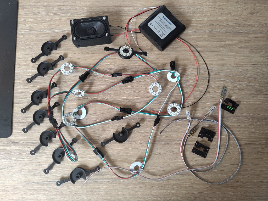
Of course, I had to think of something to accommodate my electronics in my build. Unfortunately, there aren't many standard options, but that's okay, because the designs are relatively easy and quick to implement with a 3D printer.With this in mind, I approached the project and, in addition to the tests I documented with these parts as part of my final project, developed corresponding designs and further developed them in an iterative process.
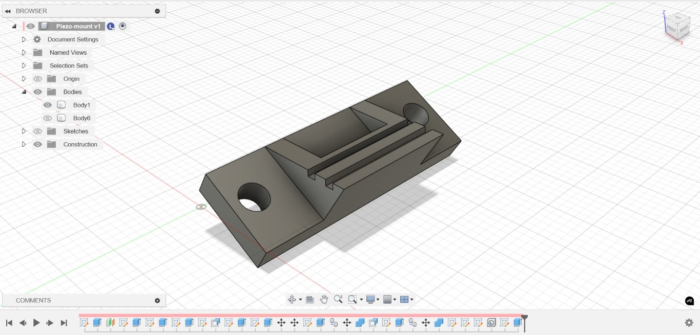
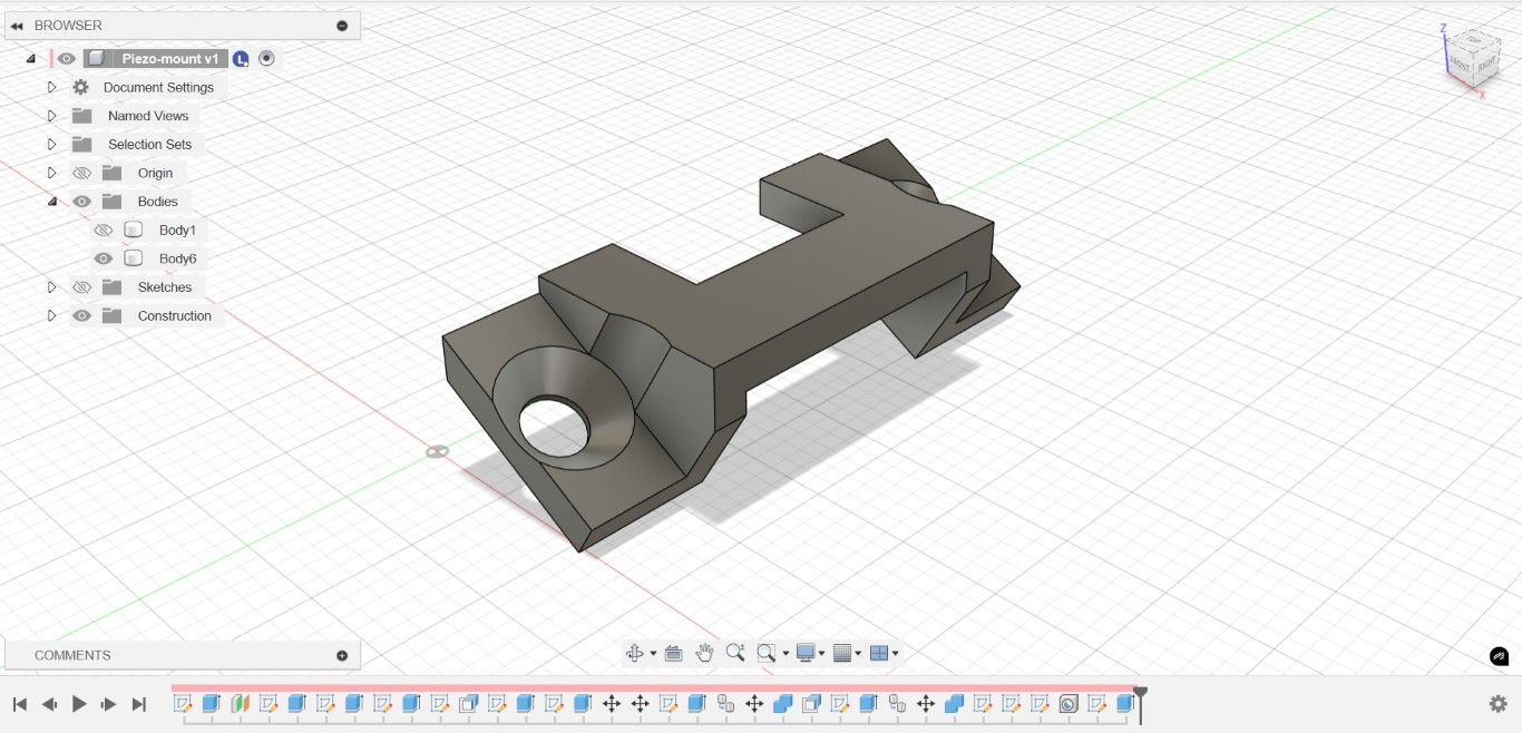
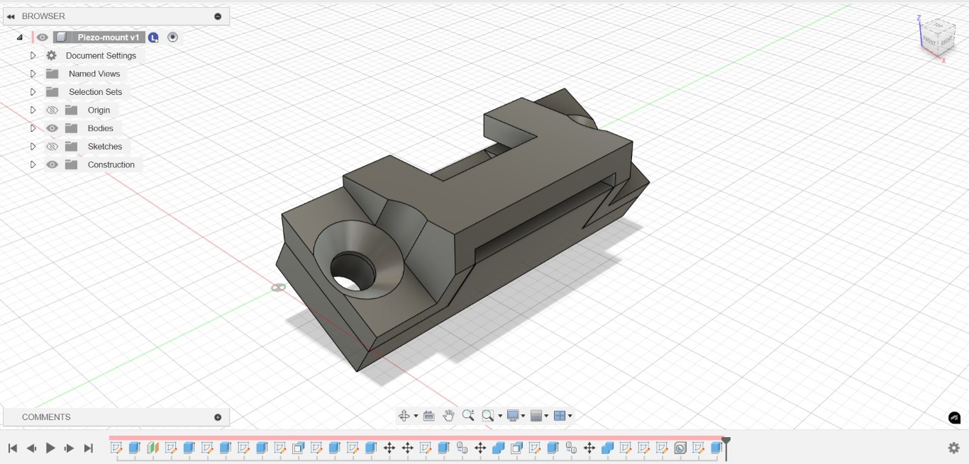
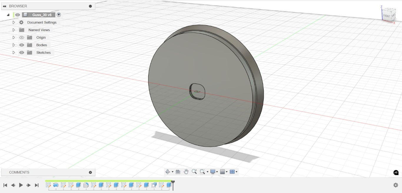
The result of this process was the following 3D designs:
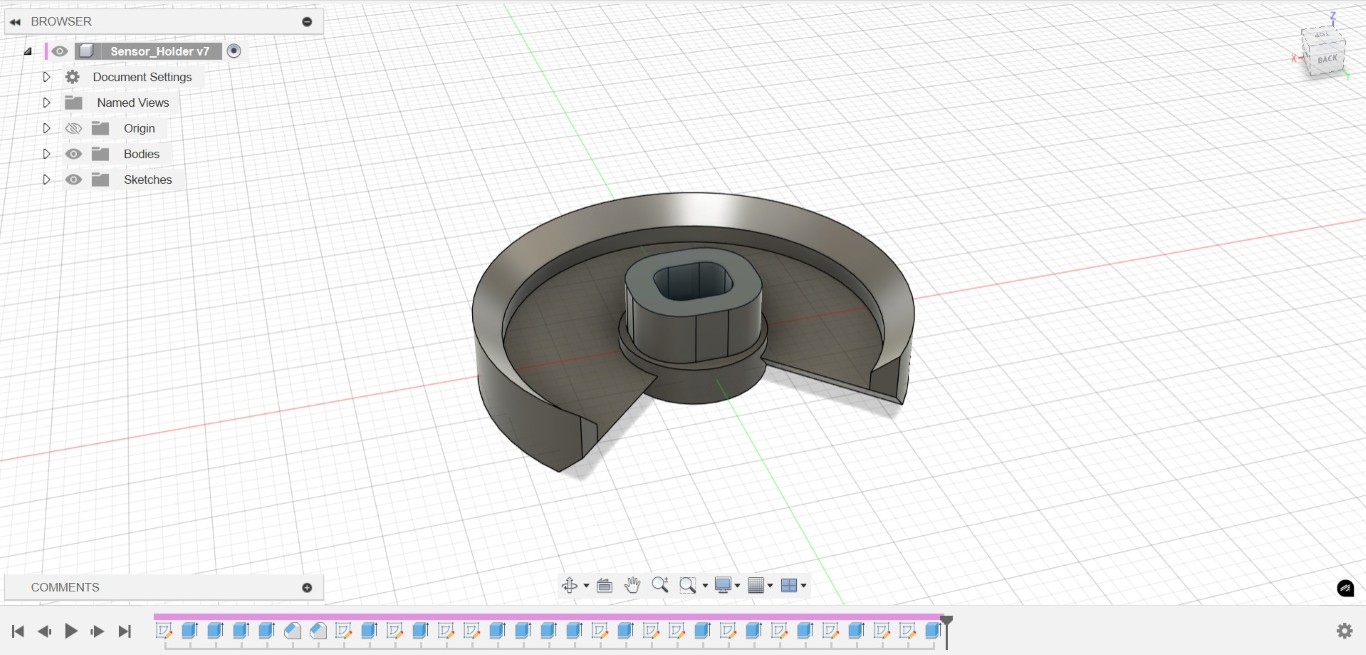
Here's just the positive part for my epoxy resin inserts, as seen in the final. The only important thing was the fit in the center, so I could center my mounts there in the next step.
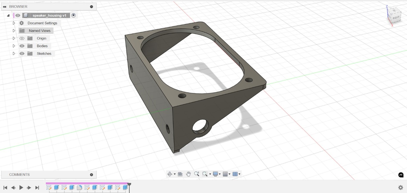
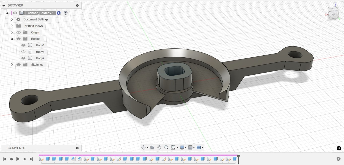
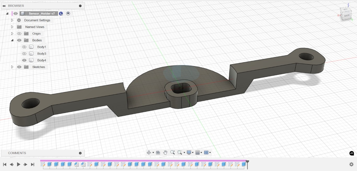
To prevent excessive clamping of the sensitive sensors, the two longitudinal cutouts on the plate serve as buffers for inserting standard household rubber bands.