wildcard week
This weeks individual assignment:
- design and produce something with a digital process not covered in another assignment
This weeks learnings:
This week was also a mixed bag. I enjoyed what I was doing, but didn't learn anything particularly new. I haven't welded in a long time, so I took this week as an opportunity to brush up on my skills. A lot of it revolved around metalworking, which I've tended to neglect before.
Pouring aid
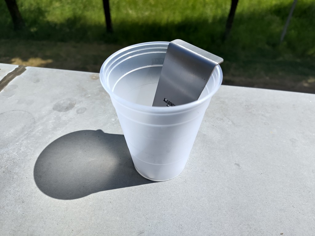
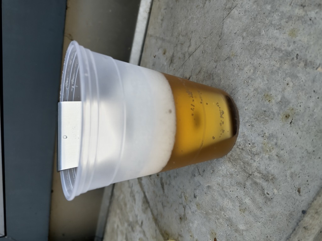
During some tests with the photodiodes, which I plan to include as redundancy to detect when a ball is in the cup, I noticed that the foam that forms when pouring the beer into the cups could be a problem.In search of something simple that would allow me to devote more time to the Final Project and my weight bench from week seven, I came up with a pouring aid for my wildcard that I could, or could, make from food-safe stainless steel I still had. For this, I took the cups from my Final Project and created a 25° angled edge that the drink can flow down when pouring, so that overall there is less turbulence and therefore less foam. The design process in Fusion was incredibly quick and is based on practical tests and measurements that I carried out, as shown in the series of images.
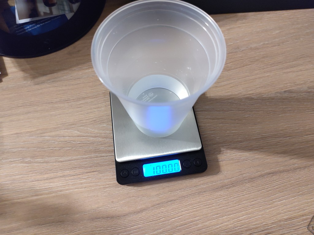
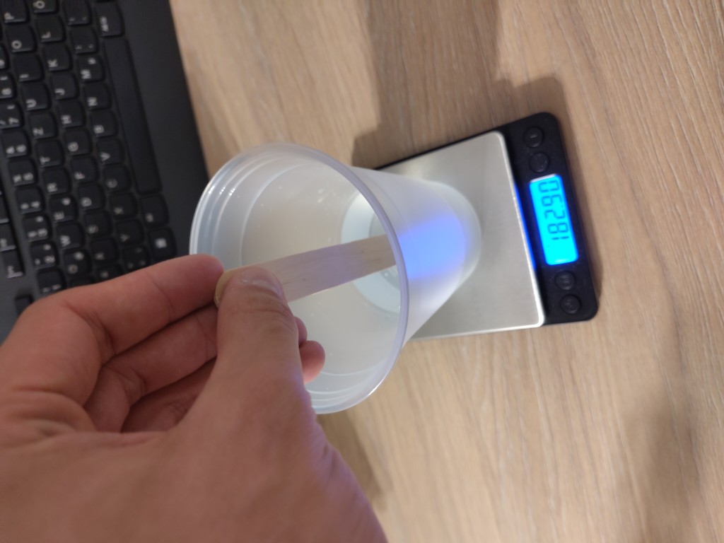
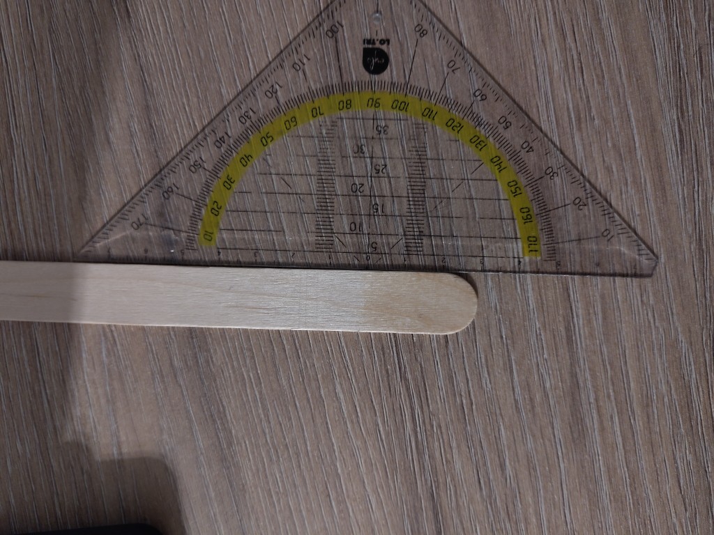
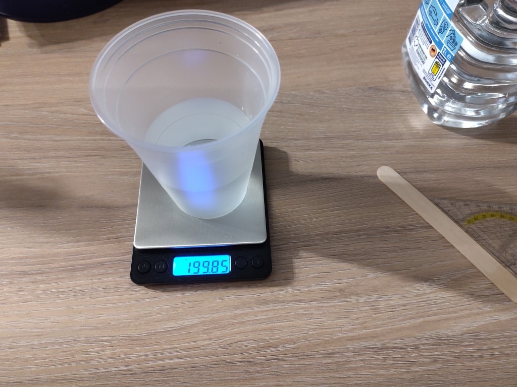
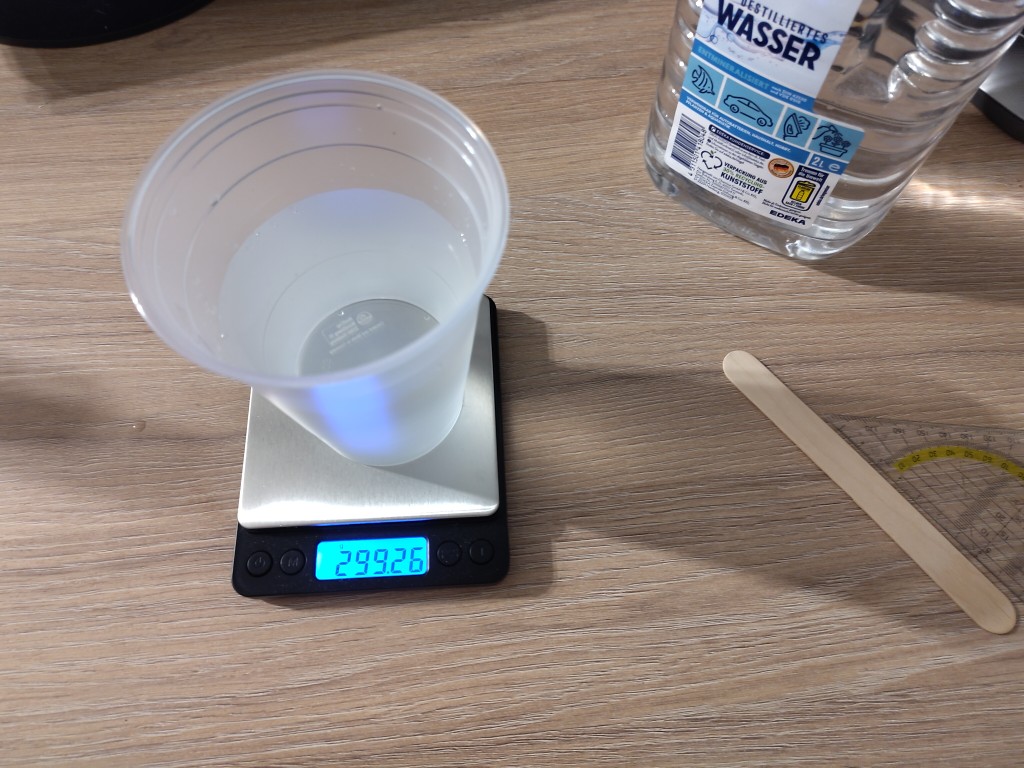
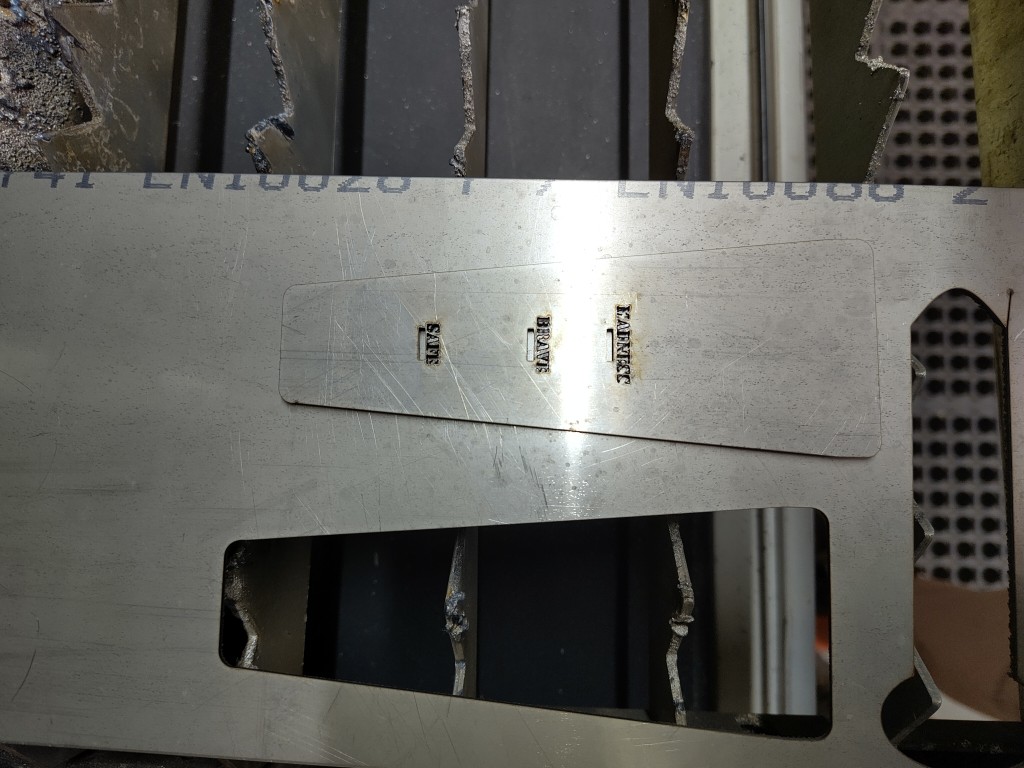
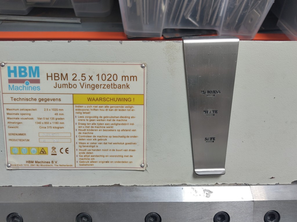
My goal was, and still is, to incorporate three calibration marks for 100 ml, 200 ml, and 300 ml, labeled "safe," "brave," and "madness," respectively. The measurements yielded the absolute heights, which I then converted to the lengths at 25° and then applied. Here's a video of my design:
Important Note: Choose a font suitable for laser cutting, so that, for example, the inner parts of "a" or "e" don't fall out. I chose the "Stencil" font, which works well.
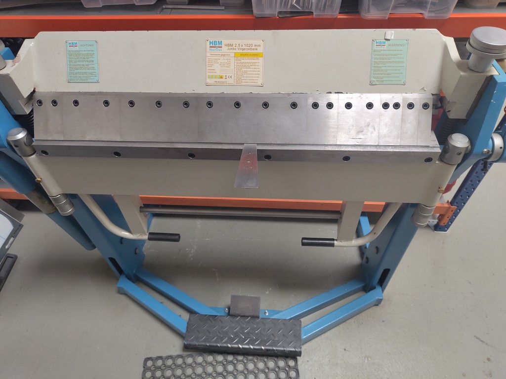
I created the surface as a sketch and exported it as a .dxf. Then I grabbed my 2 mm thick stainless steel and went to the metal laser cutter. Once there, I processed and laser-cut my material – similar to Machine Building Week. You can get an idea how in the following slideshow.
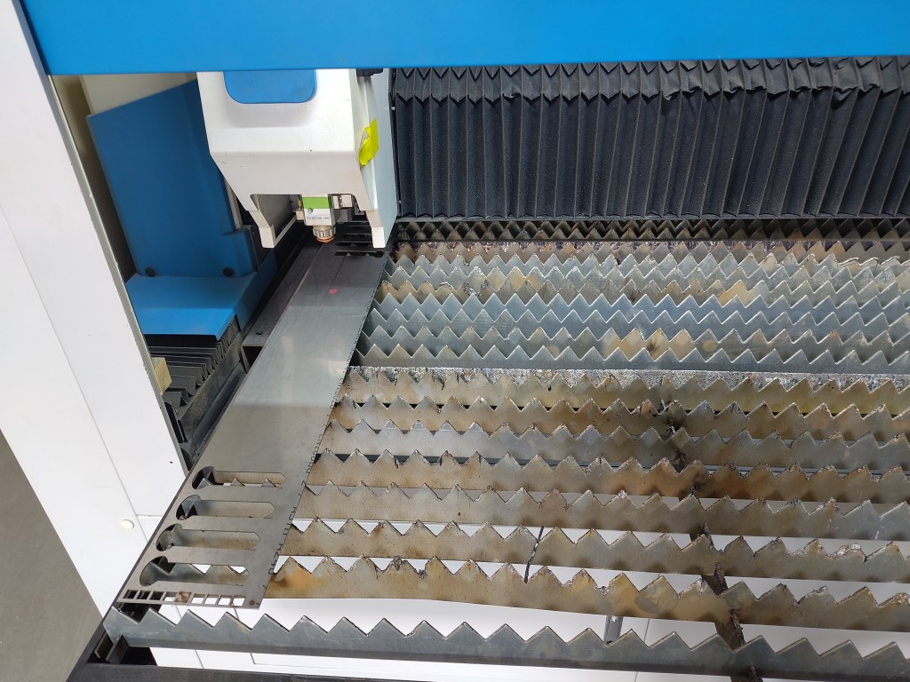
1 / 16
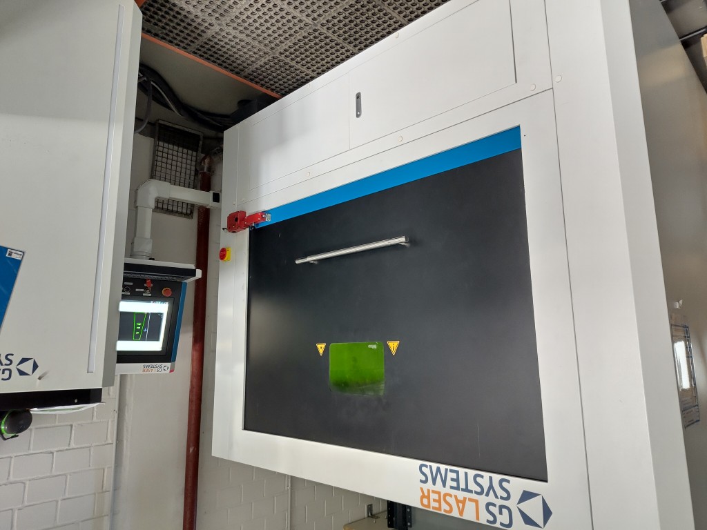
this is the small handy machine
2 / 16
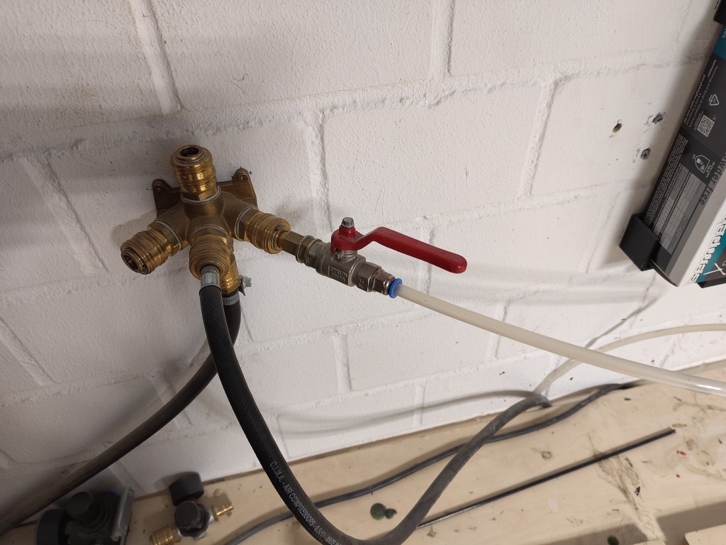
first I turned on the compressed air
3 / 16
then I inserted the stainless steel plate
4 / 16
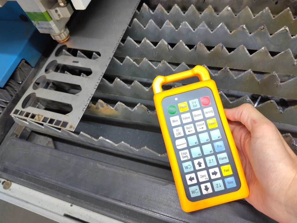
and focused the laser via remote control
5 / 16
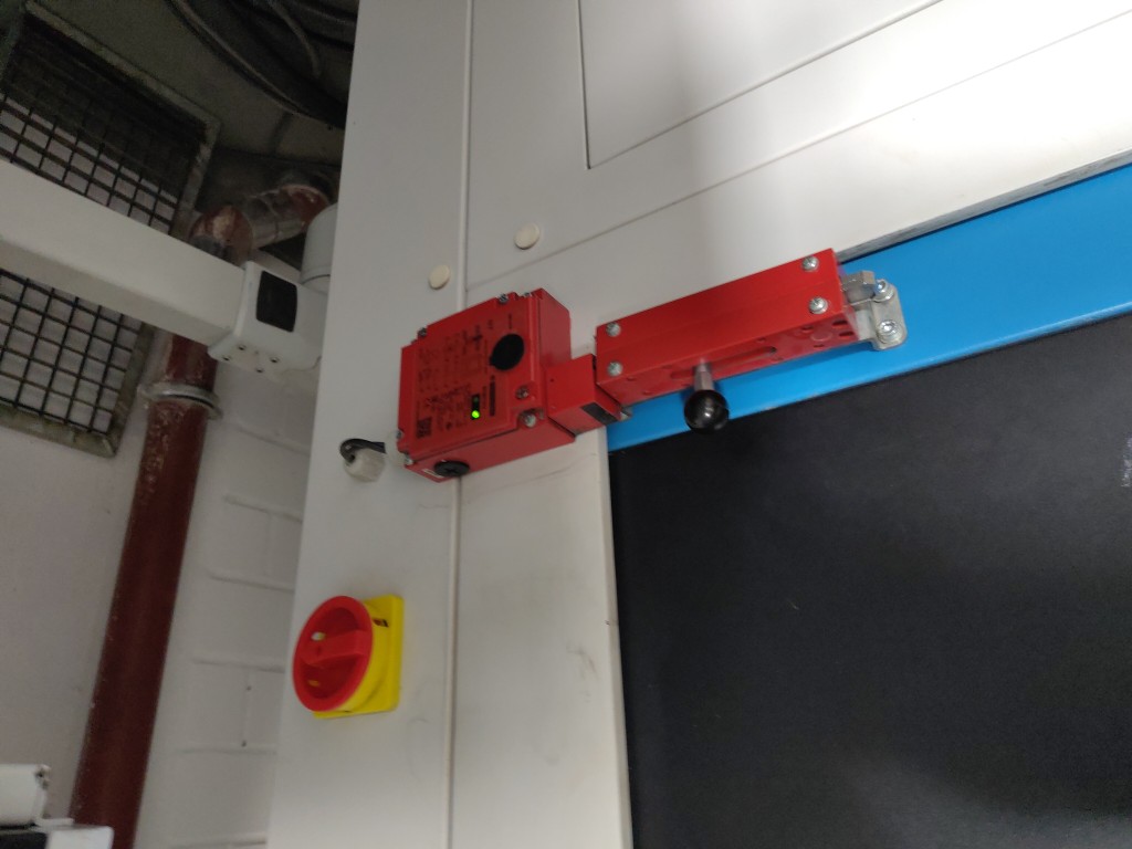
then I closed and locked the machine
6 / 16
and opened the following test file
7 / 16
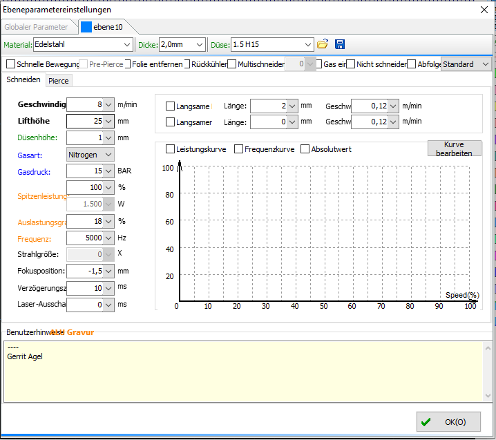
adjusted the cutting settings to my material*
8 / 16
and tried out the settings first on small test files
9 / 16
after the test was good I then opened my .dxf file created in Fusion with this result
10 / 16
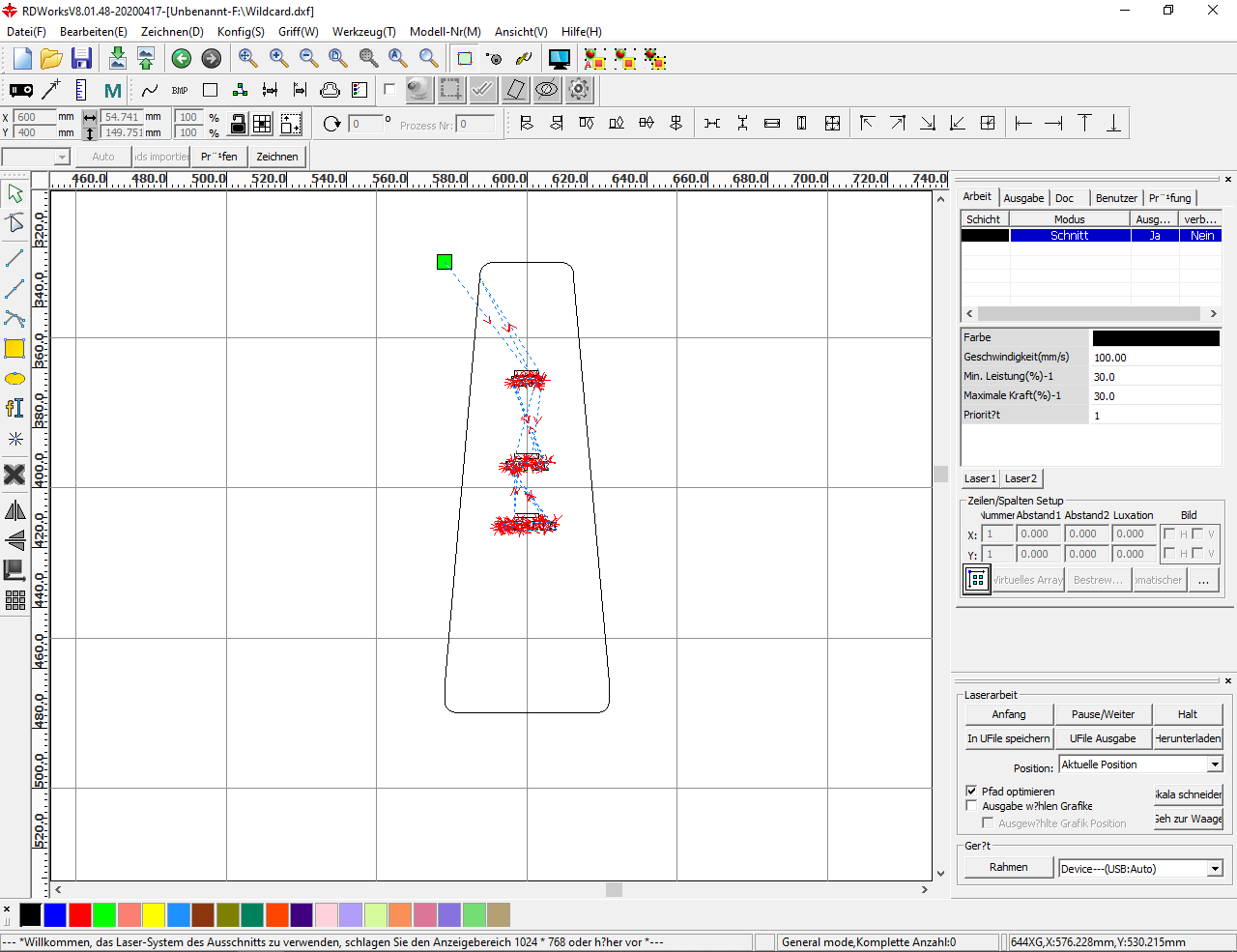
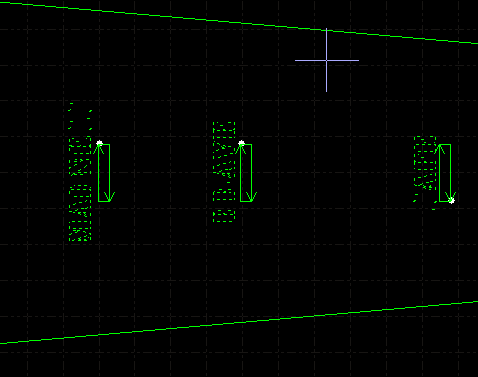
of course, it couldn't stay like that, so I loaded the file into RDWorks
11 / 16
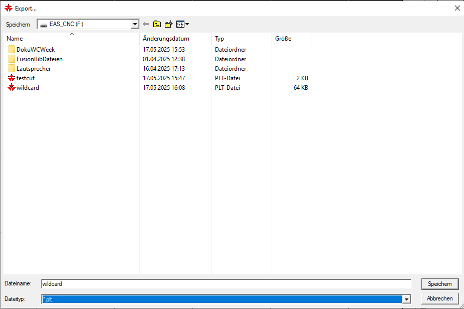
and saved it as a .plt file
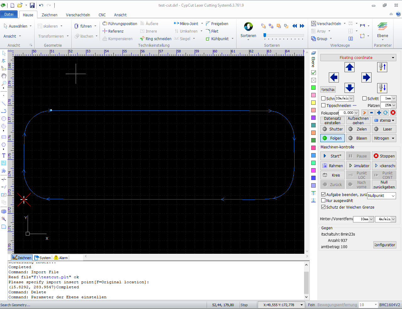
12 / 16
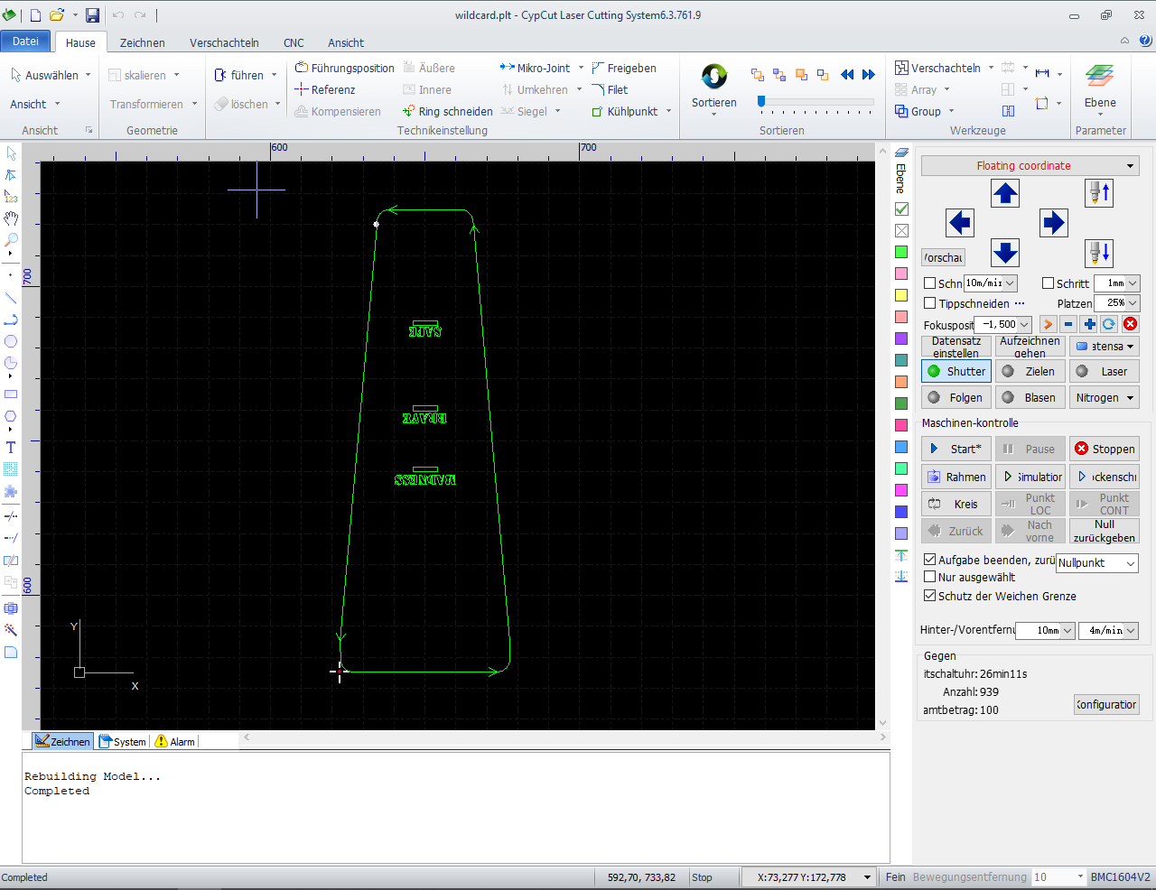
which I then opened in CypCut, already looking much better
13 / 16
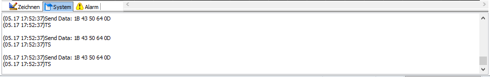
So good that I went back to the old settings and was able to laser the part after setting the origin and focusing it on the material using the remote control. You always receive a similar output from the machine as a transmission confirmation, and then you can start the laser job.
14 / 16
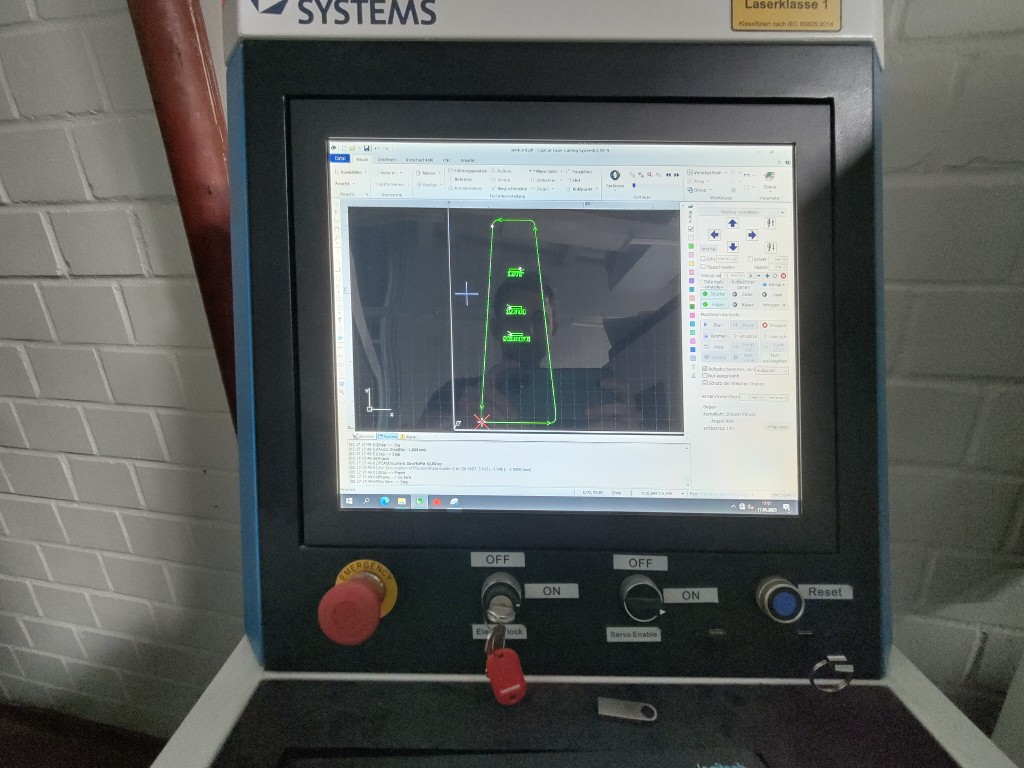
then I lasered my original part
15 / 16
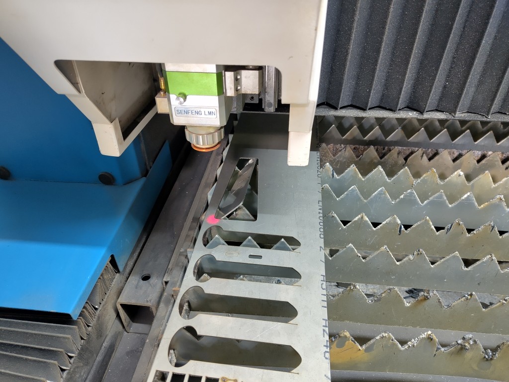
with the following result
16 / 16
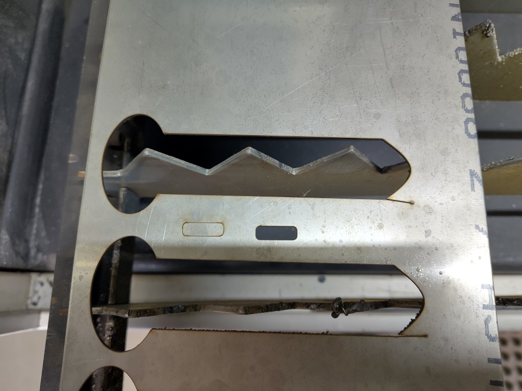
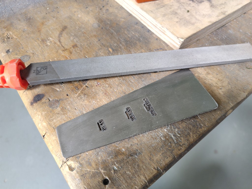
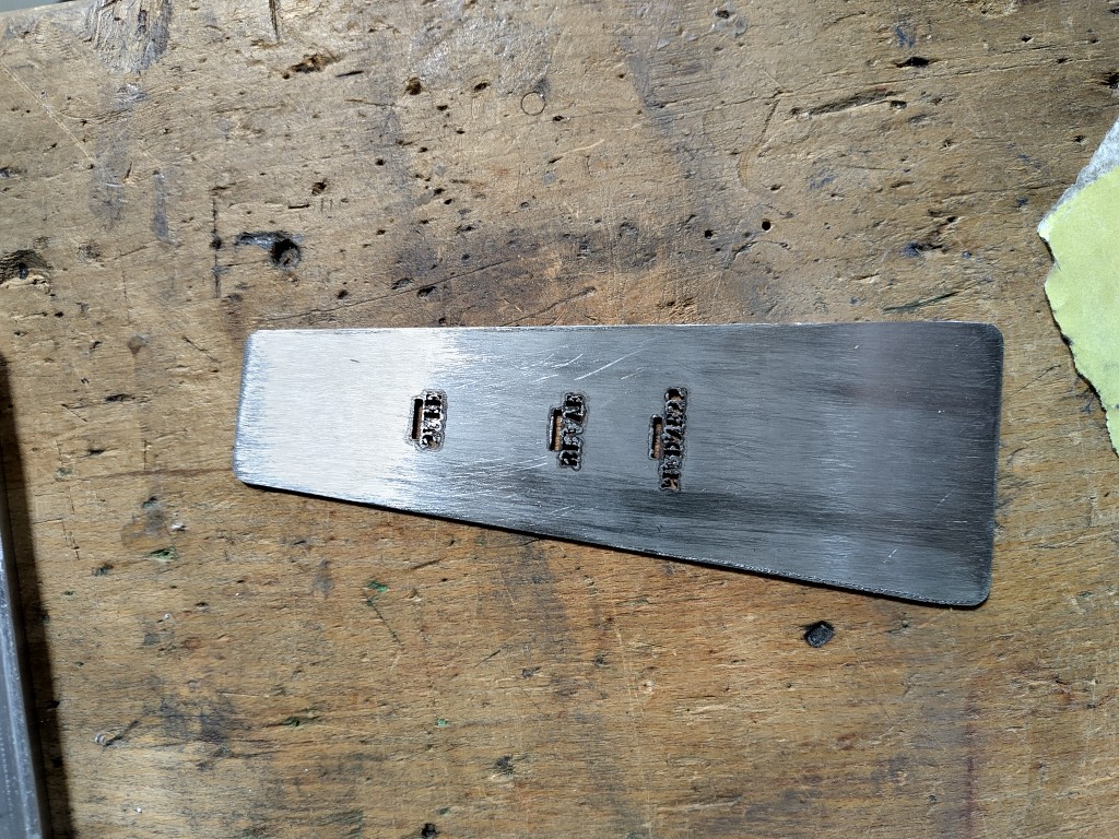
*Speed: 8m/min, Gas pressure: 15 bar, Power: 1500 W, Frequency: 5000 Hz After laser-cutting, I filed off the resulting burrs and sanded my entire part lengthwise by hand to achieve a uniform appearance – at least if you factor in the larger scratches. Once I was satisfied, I scribed and bent it according to my calculations. The result of this process was the following:
1 / 12
here you can clearly see the burrs that need to be filed away
2 / 12
3 / 12
here you can see the surface impairment caused by filing
4 / 12
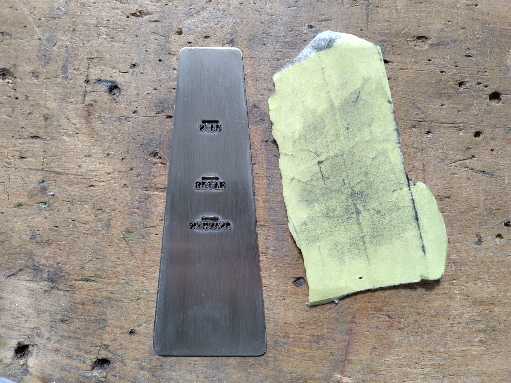
therefore I reworked with 240 grit sandpaper
5 / 12
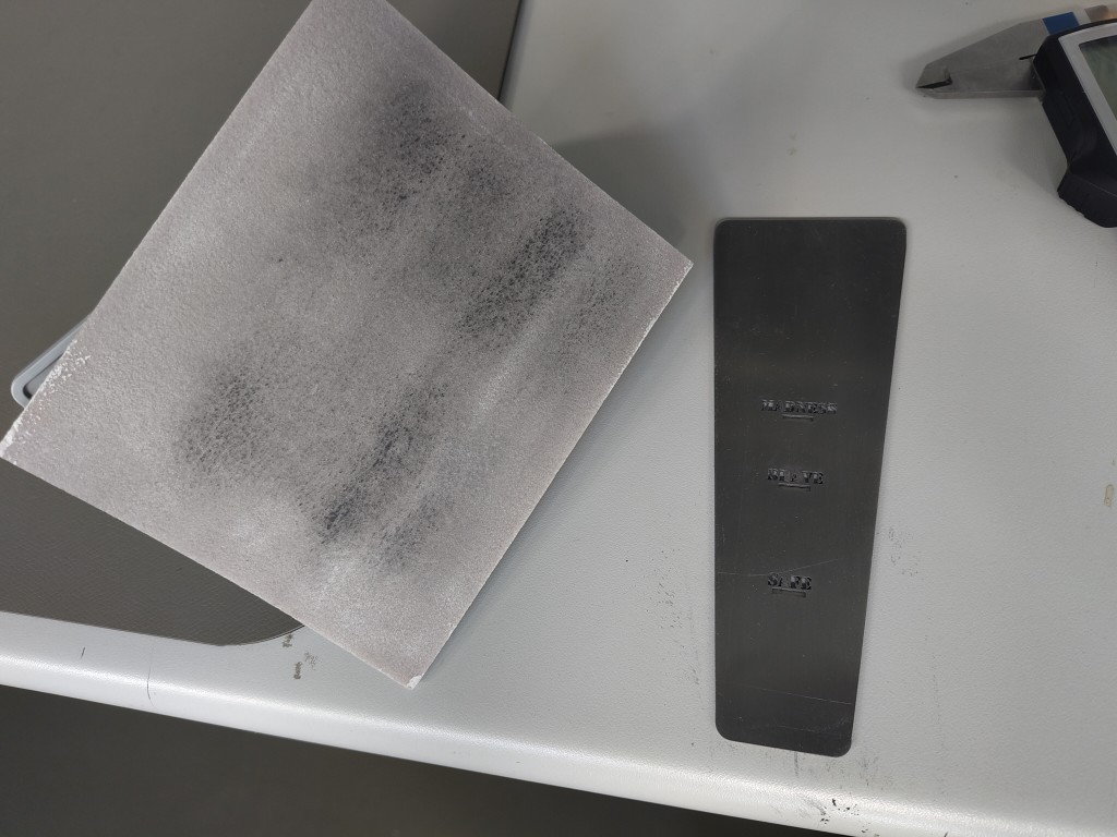
only to realize that I want it even finer. Without wanting to advertise, I can truly recommend the 3M sanding pads — they made a significant difference for me at the FabAcademy.
6 / 12
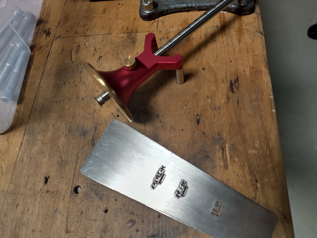
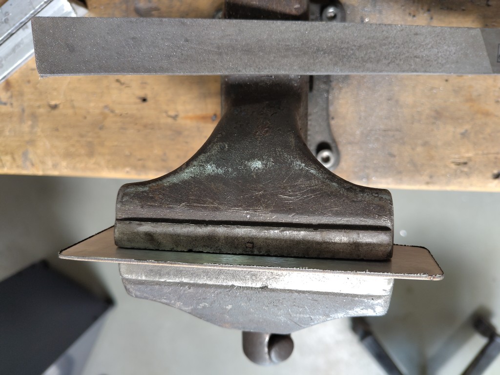
then I drew the bending lines according to the lines in my fusion360-file
7 / 12
and clamped along these
8 / 12
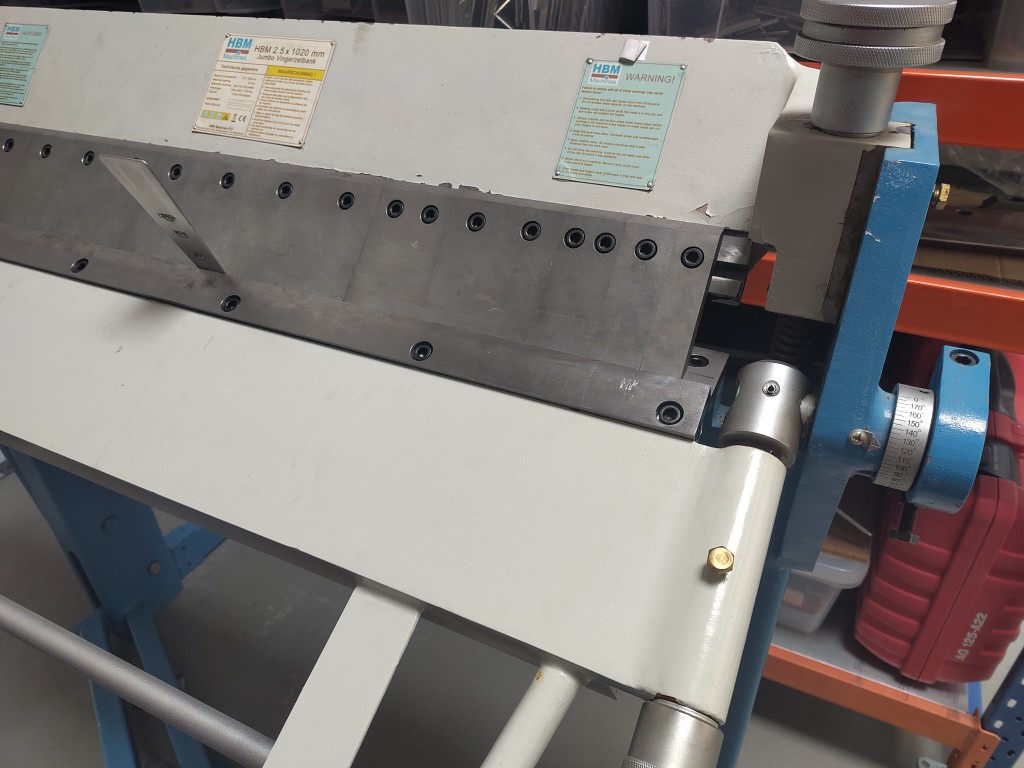
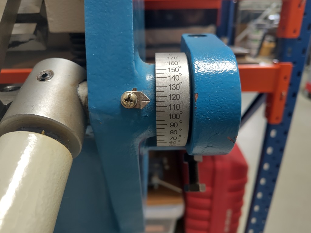
to bend a 115 ° angle
9 / 12
10 / 12
what I repeated on the other side
11 / 12
with this result
12 / 12
or more importantly: this result
Overall, the pouring aid works well. You still have to be a bit careful when pouring, but with a little practice, you can significantly reduce the amount of foam. Since Julian designed and manufactured a bottle opener this week, it made sense to combine our projects. So, cheers, Julian!
As you can probably see from the video, I was very impressed at that moment by how badly my pouring aid was working. Fortunately, the whole thing works better, in the video it must be due to the strong wind, which hopefully can be clearly seen. Julian and I were only able to stand safely thanks to our concrete shoes. To show that it works, I therefore use the Video Assistant Referee in a sporting sense:
Even if it looks staged, it is real. For the majority of the German population, i would like to point out at this point: not a drop was spilled when pouring! Many thanks to Kerstin for filming!
Since I technically already used and learned about the metal laser cutter during Machine Building Week, I'll list some more things I did this week here.
Continuation of week seven (Computer-Controlled Machining)
Maybe my weight bench from Week 7 still rings a bell, but if not, it might be worth going back a bit. To recap: This is where I ended the week.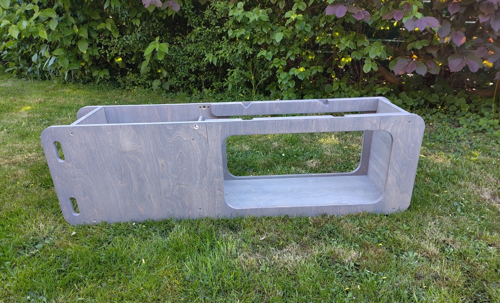
| quantity | material | dimensions |
|---|---|---|
| 1 | steel round bar | 300 (length) x 12 mm (diameter) |
| 2 | safety split pin | for diameter 12 mm |
| 2 | round steel tube | 270 (length) x 16 mm (diameter), wall thickness 2 mm |
| 2 | square steel tube | 600 x 25 x 25 mm, wall thickness 1.5 mm |
| 2 | square steel tube | 300 x 20 x 20 mm, wall thickness 1.5 mm |
| 2 | fitting screw | 8 x 50 mm straight, then 11 mm x M6 |
| 6 | steel washer | 6.3 mm |
| 2 | steel washer | 8.5 mm |
| 2 | plastic washer | 8.5 mm |
| 2 | lock nut | M6 |
| 4 | sleeve nut | max. 12 mm length, 8 mm diameter, M6 |
| 4 | machine screws | M6 x 35 mm |
| 6 | stainless steel screws | 4,5 x 45 mm |
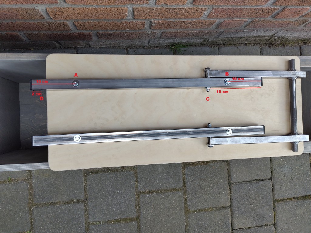
Hole C is 10 mm from the bottom and 15 cm from the top. The hole diameter depends on the fitting screw and is 8 mm or 8.5 mm in my case, respectively. Hole D is aligned with the left end and is 20 mm from it. To the bottom, it is 10 mm from the edge, with a hole diameter of 12.5 mm, due to the 12 mm thick steel axle. All measurements mentioned here refer to the centers of the respective holes.
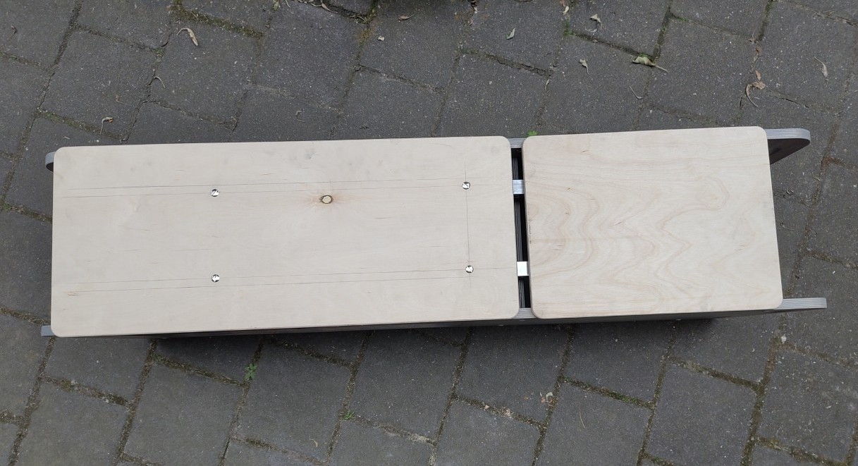
After I had drilled all the holes, it was time to transfer the holes to my wooden board. For this, I also used the marking gauge, without which I would have been completely lost in the FabAcademy. What an invention, what a tool! The holes in the wood only need to be large enough for the diameter of the sleeve nuts, which in my case was 7 mm. However, it was important to countersink the upper part of the hole so that the wider head of the nut would disappear into the wood. After that, I had to shorten my screws by hand with a hacksaw because the hardware store assumed that no one would need M6x35 mm screws. Unfortunately, the hardware store was wrong. But that didn't stop me, so I used the shortened screws to attach my boards. This worked wonderfully, but then I realized I had other mistakes in my thinking. My board was too long and, at too large an angle, was creating tension on the base. The following image probably best illustrates the problem:
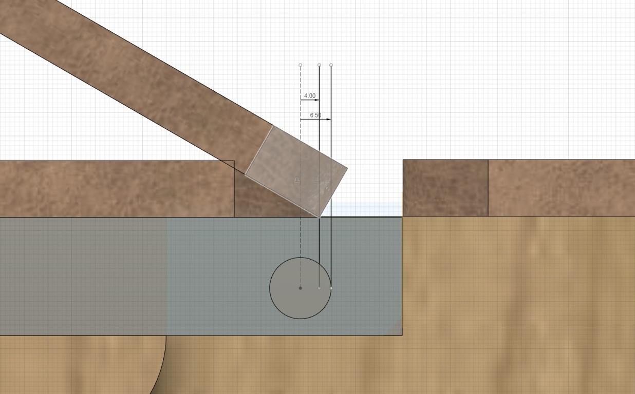
For a brief moment, I considered grinding a Swiss edge onto my board, but then decided against it due to stability and aesthetics. So, all I could do was redistribute the lengths and mill them again, with the following result, here already mounted. CAD models of these, which can be used for manufacturing using a CNC, can be downloaded below.
Here, too, I added the holes and the appropriate countersinks, and was already so much further along that my weight bench had suddenly improved its mobility far more than would have been possible with months or even years of training.
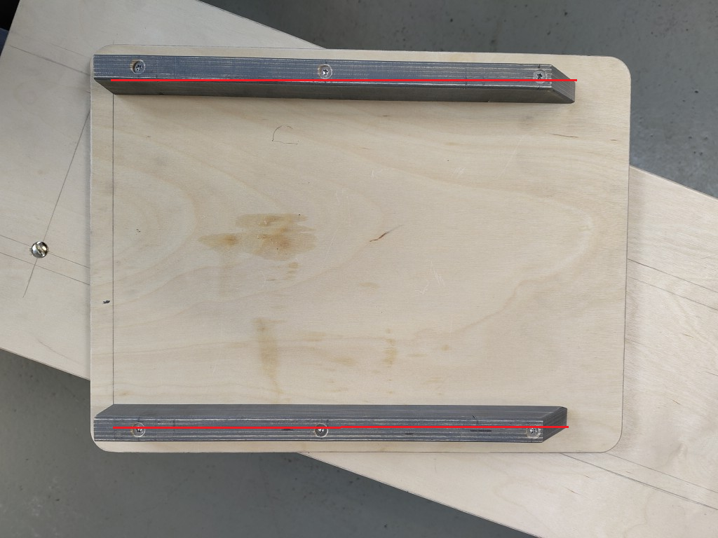
So, at this point, all that remained to be done was the seat and the padding on both surfaces. The seat was a quick job. Contrary to the original design, I used the existing wood and converted the 45° angle into a 90° angle to create a firm stop in that direction of movement, preventing slippage. To do this, I pre-drilled both boards to the appropriate size and then used the appropriate screws with the following result. The vertical parallel line has a distance of 18 mm from the edge, although a little play here is fine; 19 or 20 mm will also work. The same applies to the marked lines (trace in red) along which the two screwed-on pieces of wood are aligned.
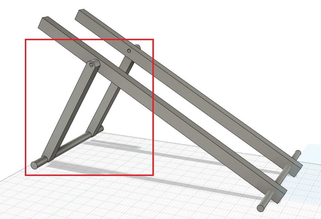
In order to be able to set up the backrest, I then had to tackle the more complicated parts, which in my case consisted of the movable angle support, which looks like this in CAD. The CAD model is available for download in my Computer Controlled Machining Week.
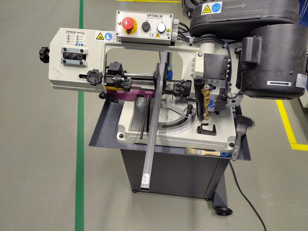
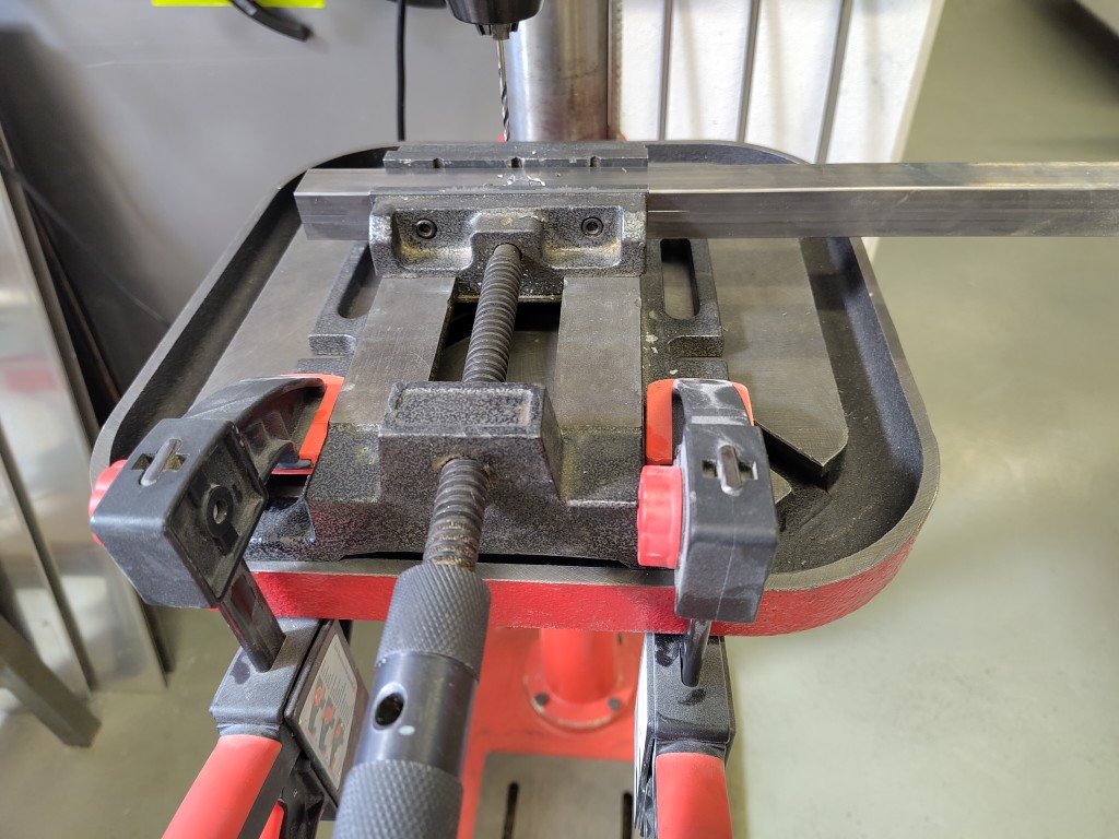
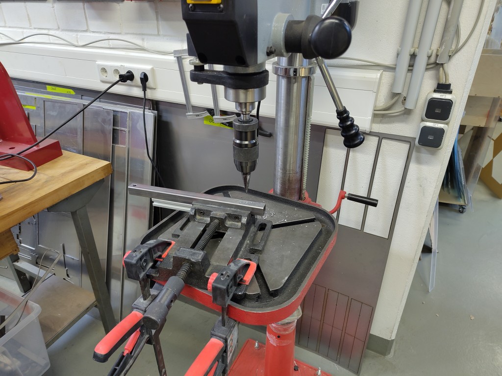
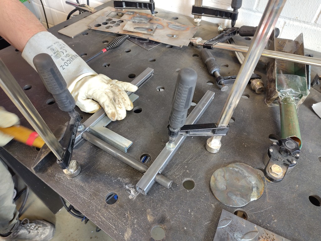
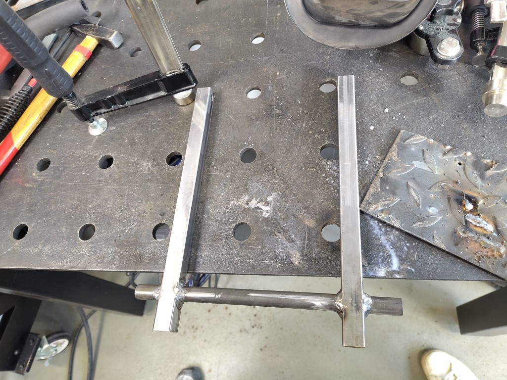
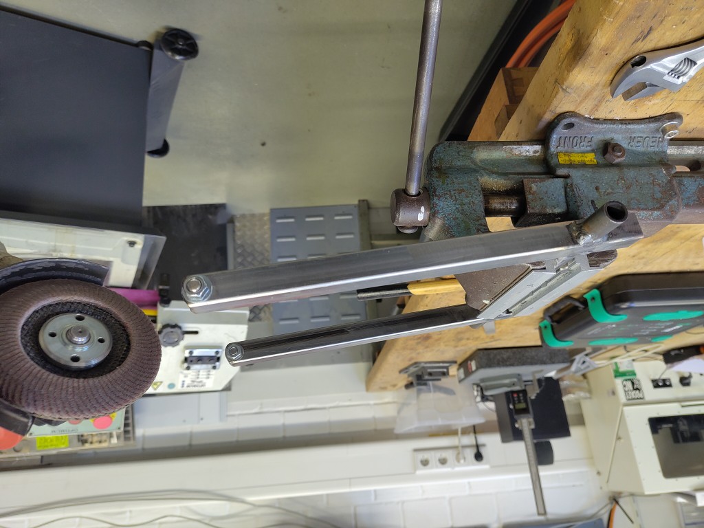
To do this, I sawed both the round steel tube and the two square tubes (20 x 20 mm) to length of 27.6 (round steel tube) and about 30 cm (square tubes). The exact dimensions of the square tubes aren't important yet, just so we have enough meat to drill into. What's more important later is the dimensional accuracy of the hole spacing, for which I recommend taking a look at my Fusion file from Computer Controlled Machining week! I then marked the holes and the upper curve and pre-drilled the holes in the square tubes to 3.5 mm, then adjusted them to their original dimensions. For the fitting screw, this was 8.5 mm, although 8 mm would probably have been sufficient. On the underside, I drilled out to 16 mm using a step drill to allow the round tube to pass through. After that, it was time to weld. Markus from the team gave me a lot of help and provided absolutely essential technical input, particularly with the angles created by the different weld points. For welding, we clamped the tube as shown; Markus also carried out the welding itself, so I only supervised at this point, even though I have welded before. Finally, the curve had to be added to the metal, which we achieved using the angle grinder. The markings weren't sufficient, so we ended up attaching a screw and washers on each side to work along with the grinding wheel. The last picture shows the result in the uninstalled state.
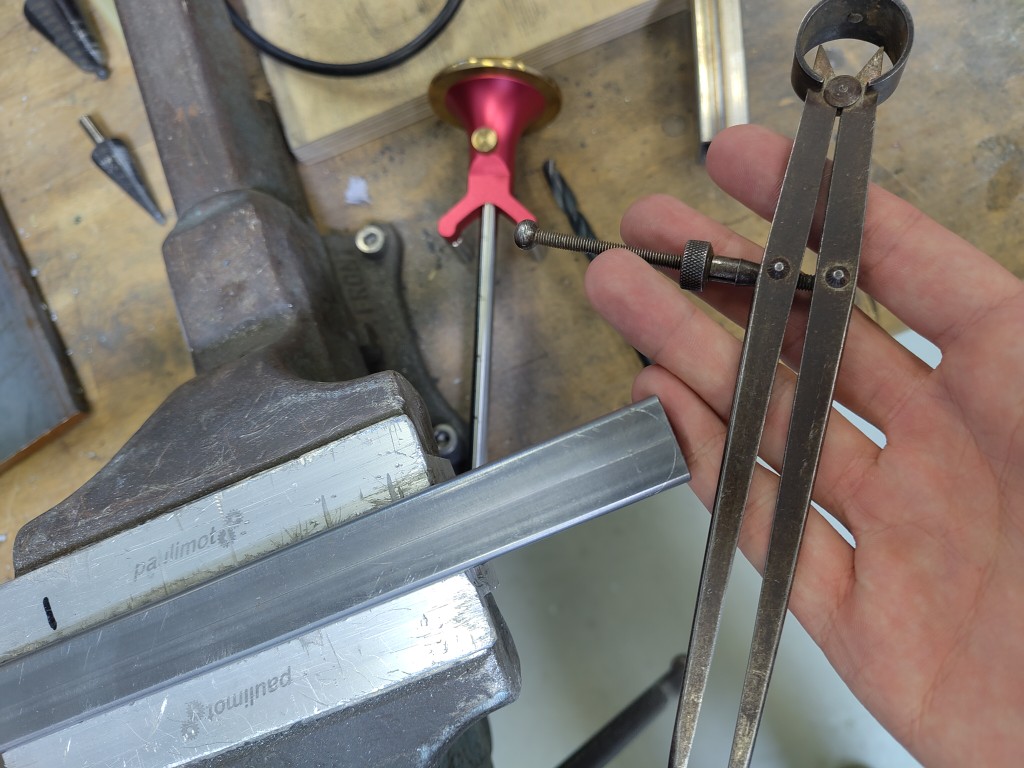
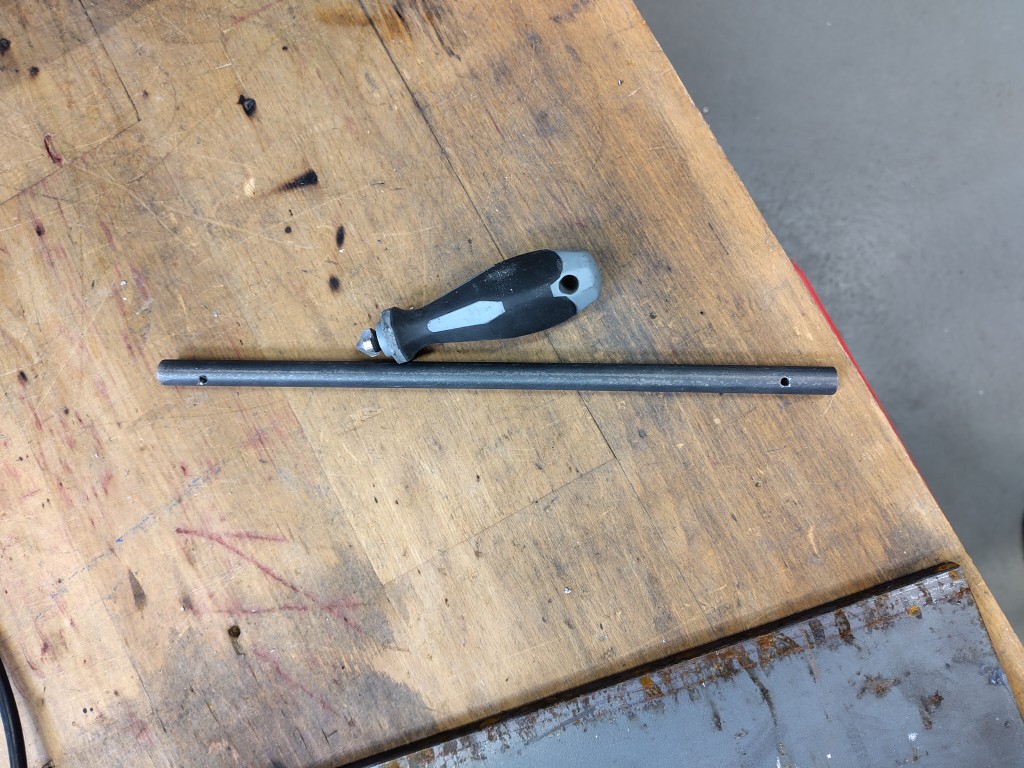
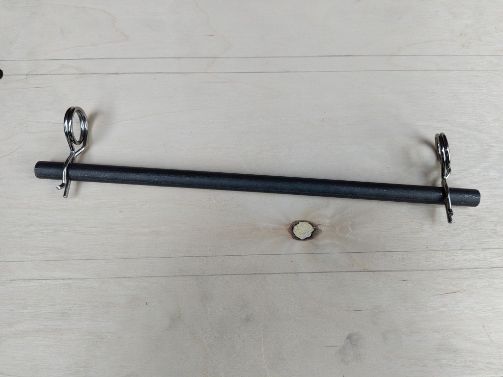
To prevent the lower pivot axis from slipping regularly or, in the worst case, from slipping away completely, I drilled two holes in it, deburred them and then inserted spring pins. The distance between the drill holes and the ends is about 2 cm each, although an exact measurement is not important here, since, as described, it is only a matter of preventing the axle from slipping out.
I had already realized that my cutout for the non-inclined position with a continuous round steel tube would be problematic, to put it mildly. Because I didn't want to resort to small pieces of tube due to the lever, I repaired the cutout using a custom template and my hand-held router. Apart from the fact that I had to apply hard wax oil again, this is what the whole thing looks like.

All that was left to do after that was to laser-cut the PU foam, cover it with fleece, and then stretch the synthetic leather over it. For aesthetic reasons, I then covered the backs with black fabric. Here, too, the process is hidden in the following slideshow:
With all this work, the result and thus my hero of this week was the following:
Just to show that the bench is trustworthy. Here it is loaded with about 150 kilos. One of the moments where I personally felt the least pressure at FabAcademy. Maybe next year you will!