My final project
Initial thoughts - Week 1
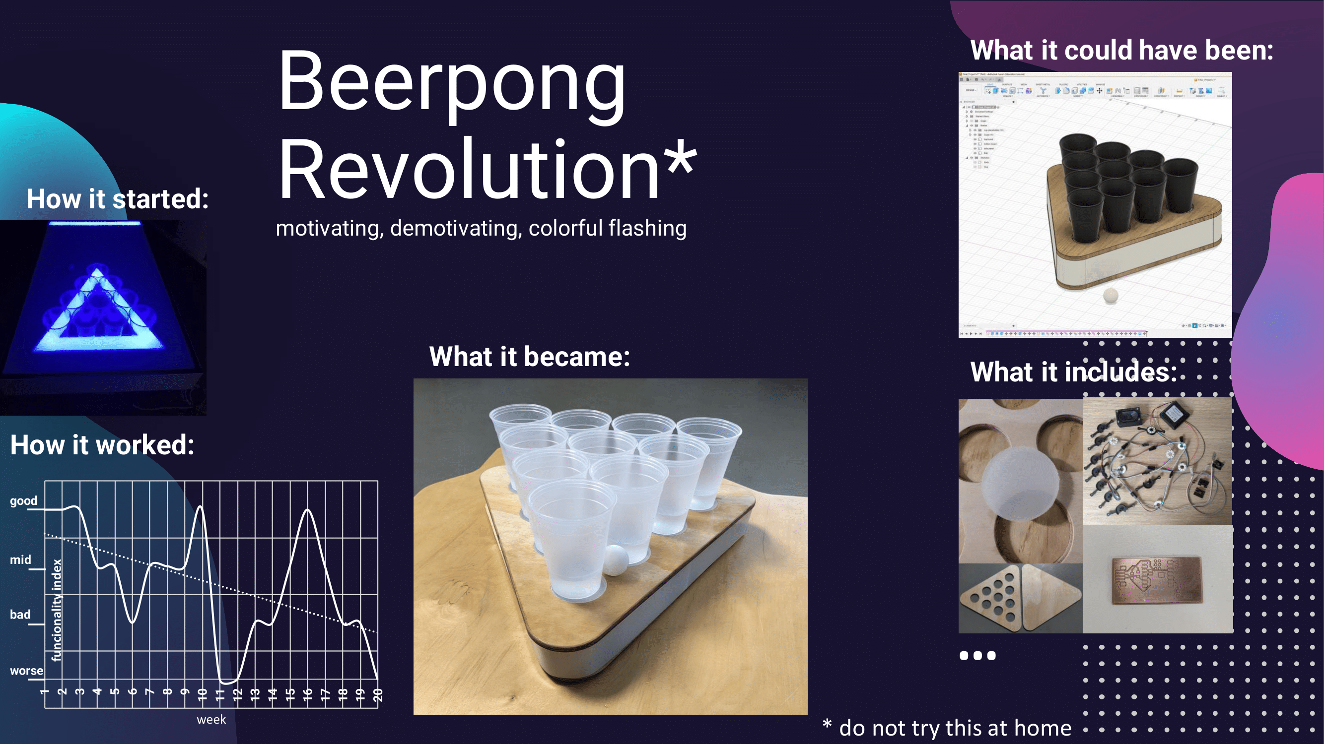
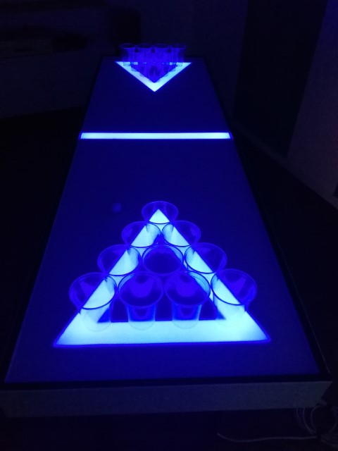
A few years ago, I built a Beerpong table that is illuminated with LEDs and changes color when the ball ticks. The whole thing was more of a coincidence, however, because I didn't program or install any controllers or anything similar, but instead used the music function of the party LEDs.
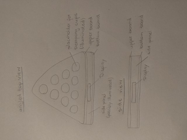
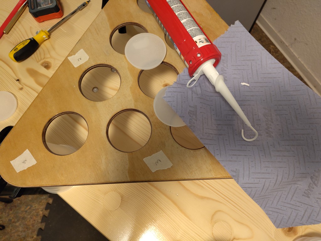
Since then, I've wanted to make the whole thing better and more portable and smaller. So for the final project, I'm concentrating on the hit surface, which has space for ten cups and can be placed modularly on any table. The cups are to be illuminated from below, which is why there are
placeholders on the top board, which will probably be cast from semi-transparent Epoyid resin later on. Below the top board, I would like to attach vibration sensors to try to detect when a cup is hit and then play various light animations. I might want to use a display to motivate or
demotivate the team behind their cups and add different features later on.
All in all, it will be a triangular structure made of two wooden boards and side panels with a cavity that I want to use for light installations and the installation of the electronics. This would allow us to play Beerpong in style at Fab25 and afterwards, of course.
Computer Aided Design - Week 2
Because I would otherwise find it odd to only show content about file compression in the Computer Aided Design Week tab, most of the work this week can be found there. I just want to give you a quick update here in the form of a video that I created in Fusion 360 and edited with kdenlive. It shows the design process and, at the end, an animation that is intended to illustrate a successful throw in beer pong. The choppy course of the ball is not really intentional. I have to simulate the ball's trajectory using a sequence of different positions, so this is a movement sampled in this way, and I would have had to invest a lot of time in making it look smooth for the eye. Unfortunately, I didn't have the time at the moment - perhaps there will be an update here in the future. Grab something to eat and make sure you have enough to drink and enjoy the next eighteen seconds. This is the current status of my final project after week 2.
Computer Controlled Machining - Week 7
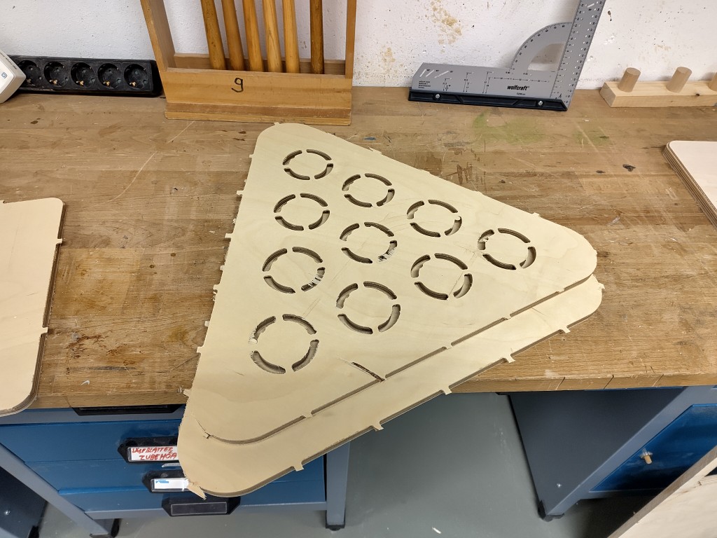
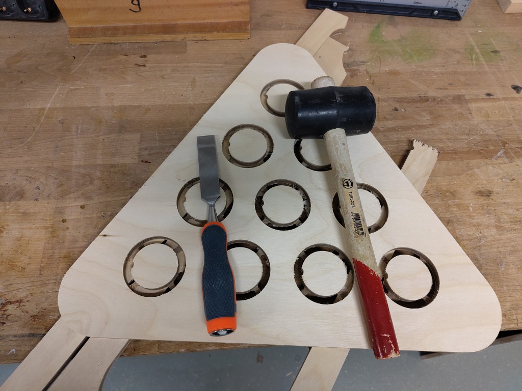
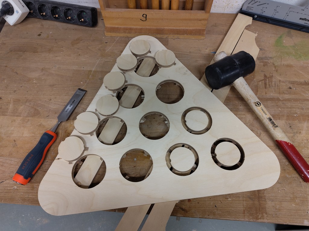
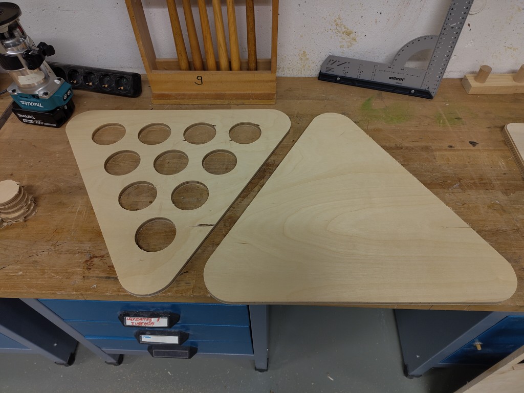
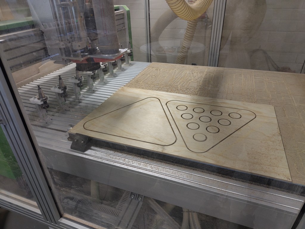
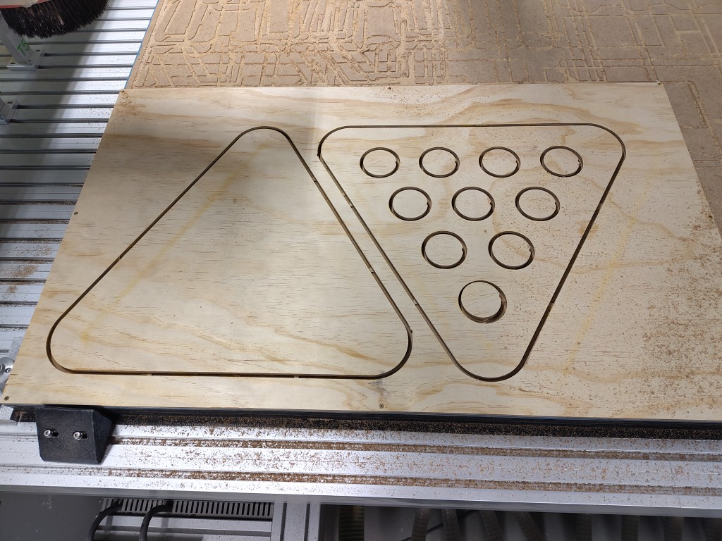
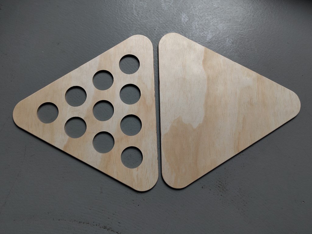
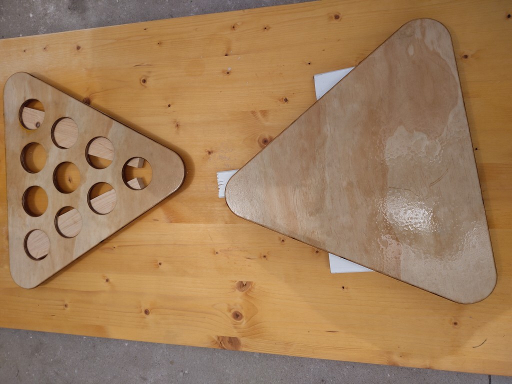
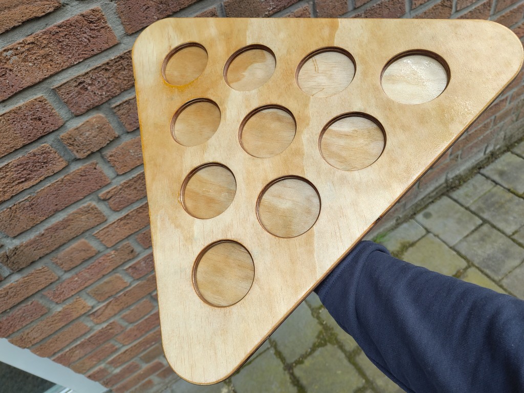
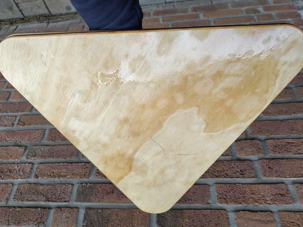
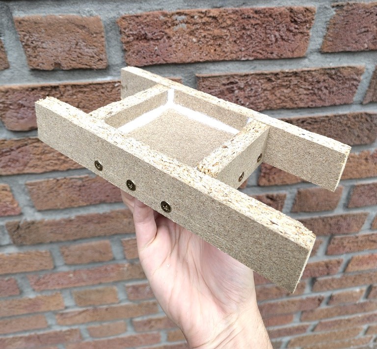
As described in my assignment for the corresponding week, I mounted my own milling cutters on the machine. To work as efficiently as possible and avoid duplicating the work, I milled the upper and lower plates for the prototype of my final project in addition to the parts for this week. I used a 12 mm plate for this, and in the Fusion setup I first machined the 2D contours with the 8 mm roughing cutter and then finished them with 6 mm. To be on the safe side, I installed retaining bars in each case, which I later cleanly milled away with the hand-held router. I then slightly rounded the edges with another cutter in the same way, with the following result.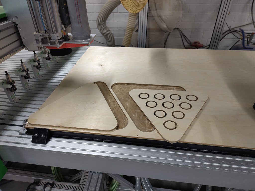
By manufacturing the parts this week, I hope to be able to better estimate how many LEDs I'll need later, which will allow me to dimension my mobile power supply and other components on the PCB based on that. It also gives me the opportunity to use sensors to test my ability to detect hits in cups.
Input Devices - Week 9
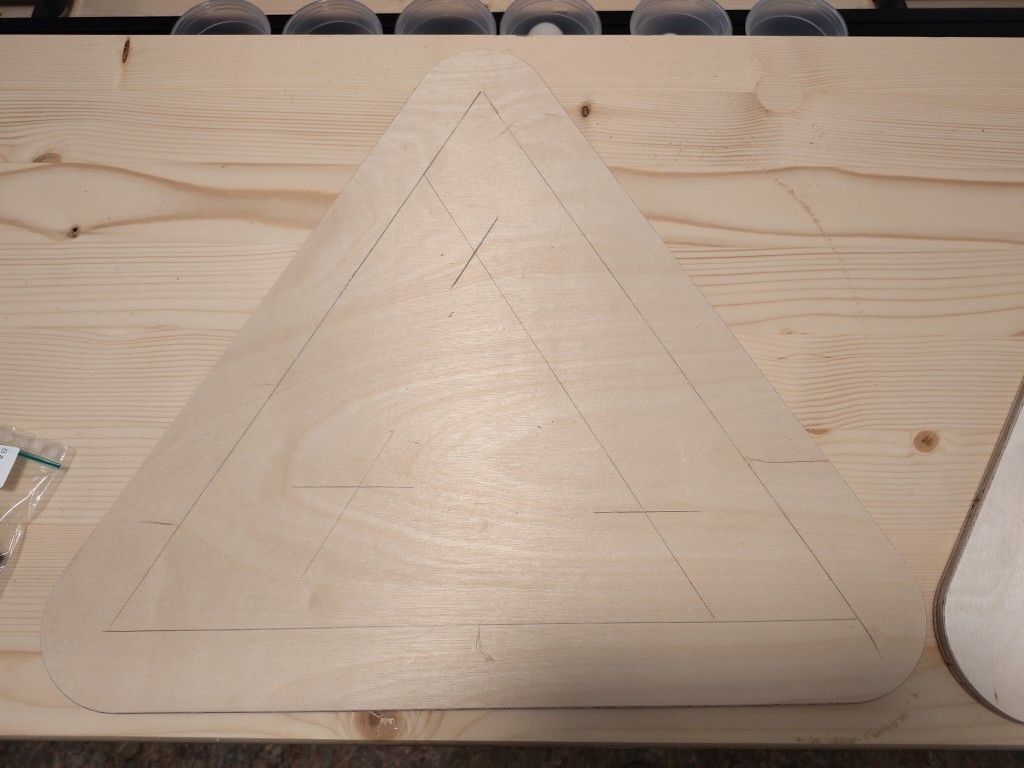
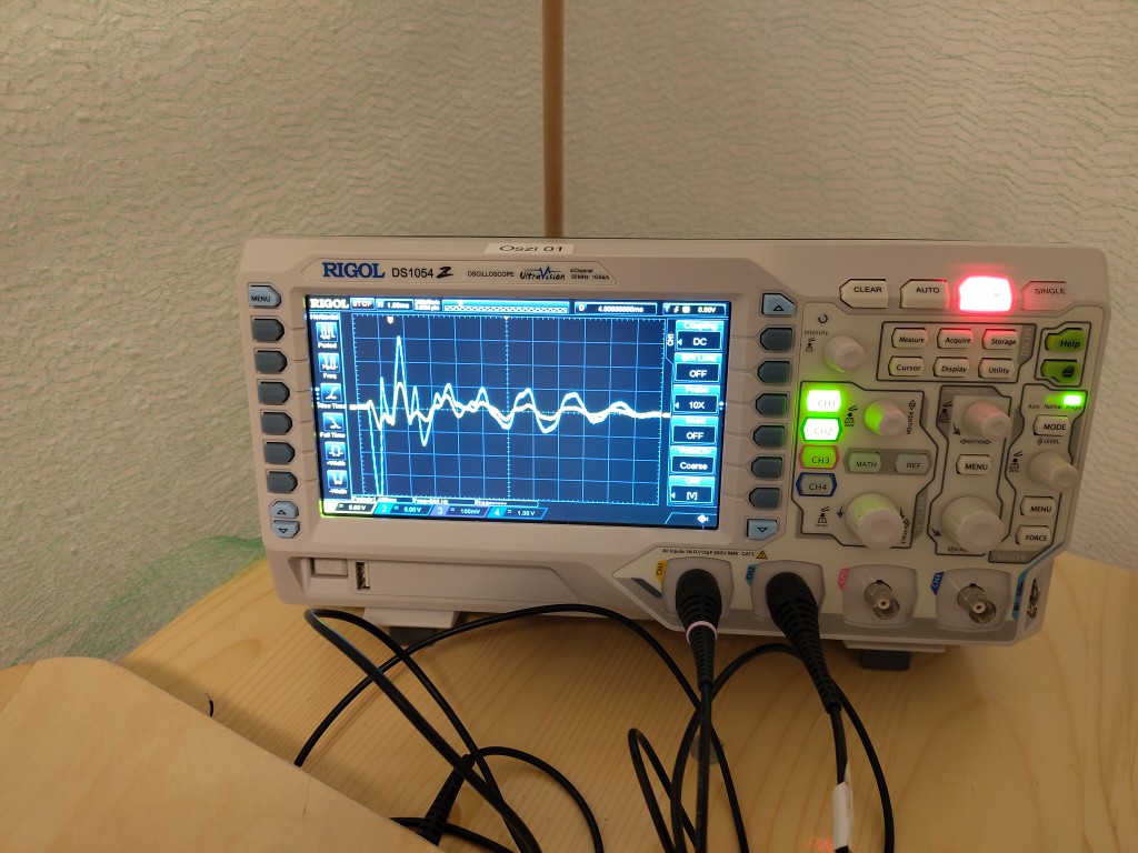
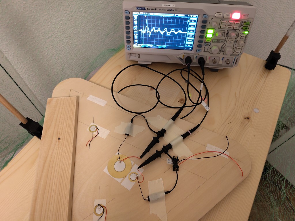
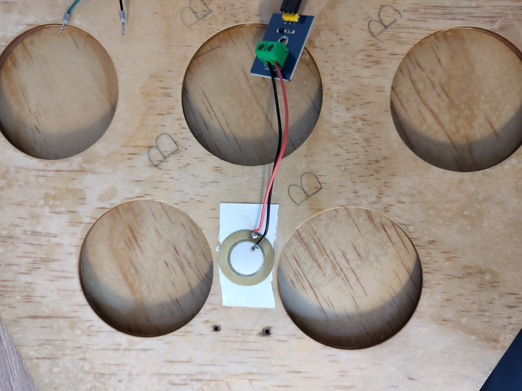
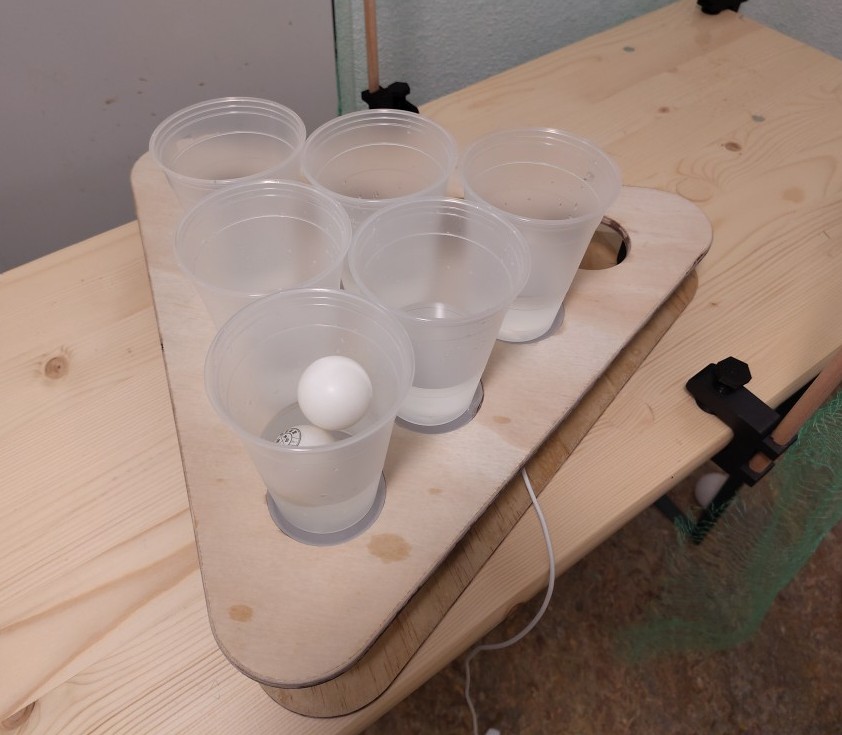
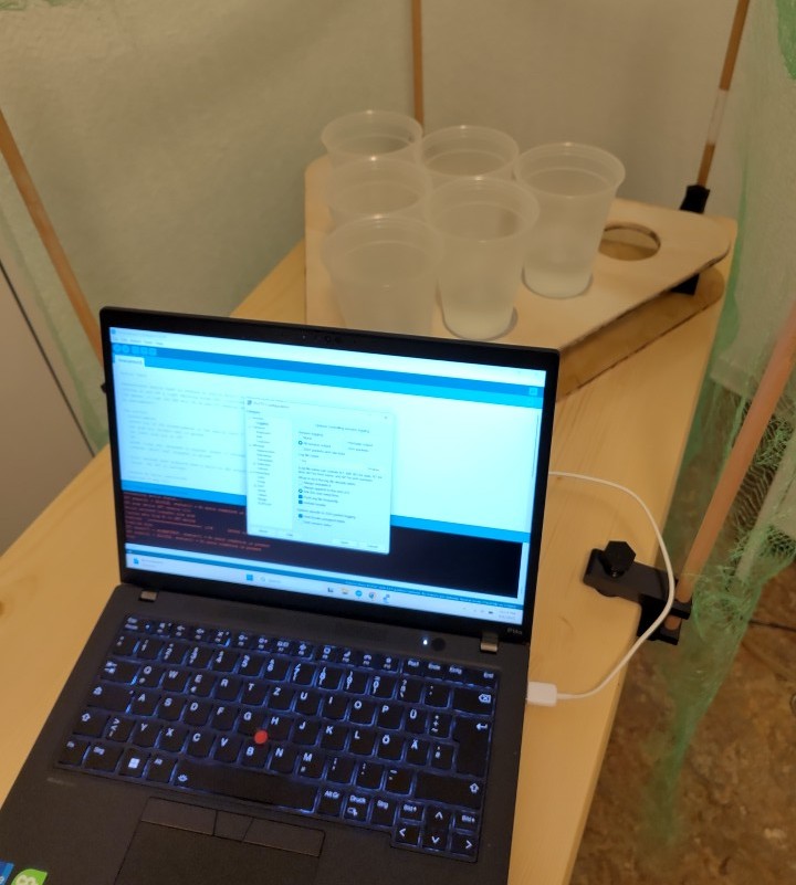
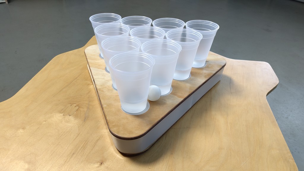
This week, I used the group assignment to validate my proposed measurement principle. Ideally, I would like to implement hit detection based on vibrations. To potentially detect the cup being hit, I need to be able to triangulate between measurement signals. To do this, I need to accommodate at least three sensors, which is why I marked three points on the bottom plate that would be suitable for mounting. I attached the sensors to these points using double-sided tape and connected them to the oscilloscope as shown in the group assignment. Then I turned the setup over and placed the cups on top to make test throws. I didn't use the actual top plate for this because of the holes.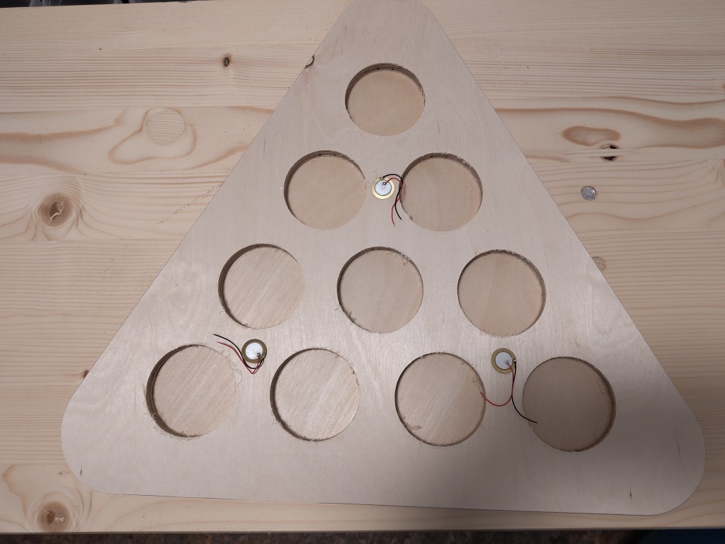
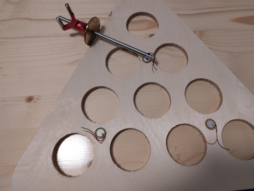
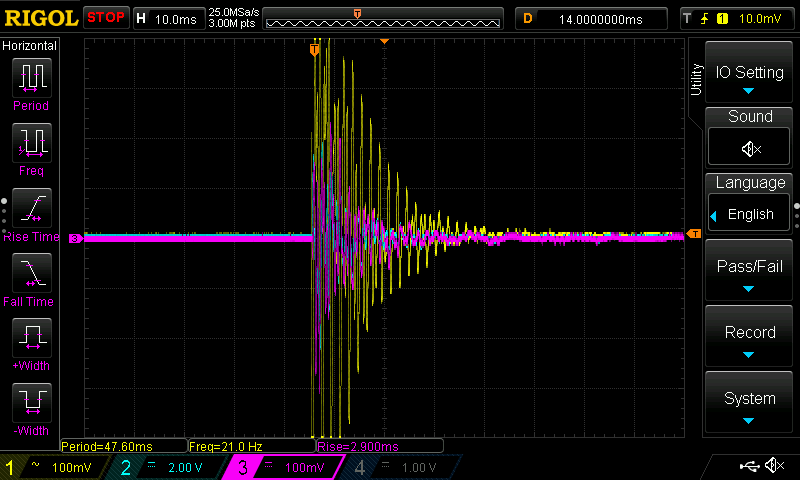
True to my theory, a throw onto the rim of the cup should result in a stronger vibration than hitting the cups filled with water for the test. This was also the case in practice. There is a problem with throws that hit the water without touching the cup; these did not show any significant deflection on the oscilloscope that could be analyzed later. So, my system currently seems to be blind to these types of throws. Another theory, which has been confirmed in practice, is that the vibration frequency is dampened and thus slowed down when the ball hits the cup, i.e., when it comes into contact with the water. Here are some measurements. Unfortunately, the three identical sensors have different sensitivities; please note the box widths below for the measured values.
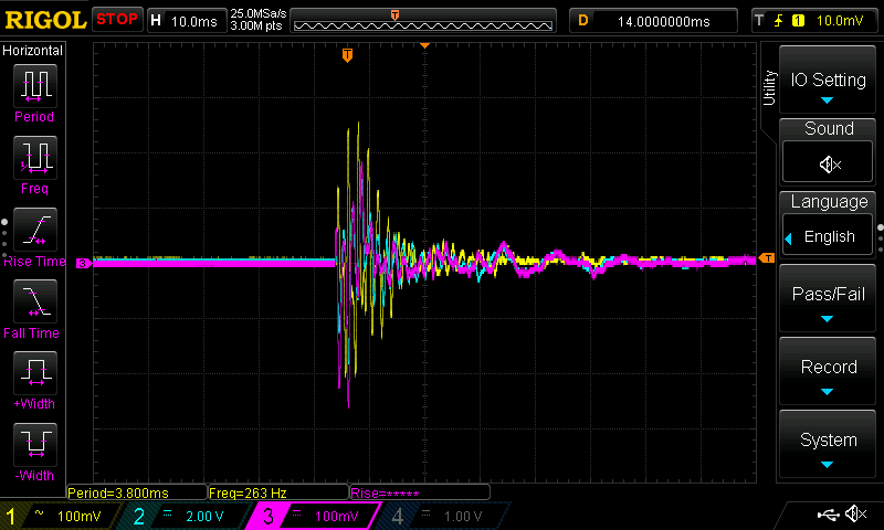
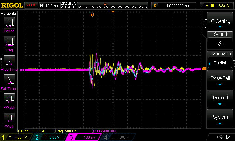
The package from Digikey, which with any luck will reach me before the end of this century, contains vibration sensors that deliver an output voltage of up to 80 V. The sensors used for the tests delivered values of up to 5 V, depending on the vibration, so I hope this will increase the sensitivity and allow me to improve the results. I'm also considering using thinner wood and mounting it in a way that allows it to move slightly, if possible, to better transmit the vibrations to the sensors. I also want to test light sensors as a redundancy, since the cups will later be placed on translucent material and ideally also need to be illuminated from below. To have this option, I bought some transparent cups a few weeks ago. That's all the testing for now.
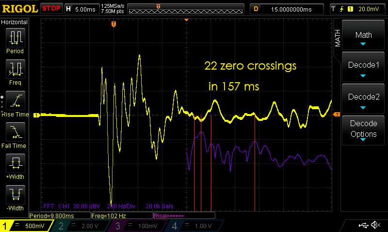
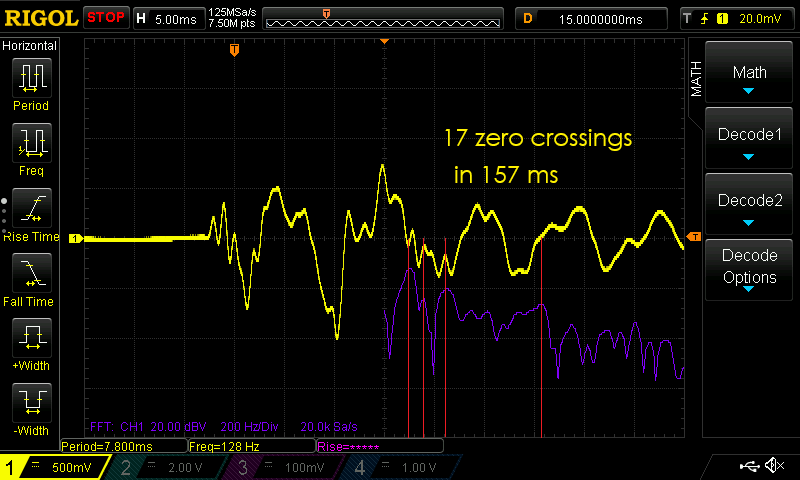
In addition to the pure amplitude of the signals, I want to use frequency analysis to draw more precise conclusions about the type of hit. To do this, I use the Fast Fourier Transform (FFT) to decompose the time signal into its frequency components. Different types of hits—such as a ball hitting the table or directly into the water—hopefully produce characteristic frequency patterns. Edge hits might exhibit higher frequency components, while a ball falling into the water should cause a more low-frequency oscillation. By analyzing the frequency spectrum, I can define thresholds for different hit types and thus improve detection accuracy. The FFT decomposes the complex signal into its individual frequency components and shows which frequencies are contained in the signal and how strongly they are represented. The result is a frequency spectrum—a kind of "fingerprint" of the hit. The combination of amplitude and frequency analysis offers me, in the best case, a more robust differentiation option than measuring the amplitude alone.
Further work - Week 10
Since I had more or less finalized my measurement setup, I tested the new sensors after they arrived. At the same time, I tested the oscilloscope's Fast Fourier function. Given the results shown below, I may have to look for other solutions or keep the Fast Fourier analysis very specific. Another source of error that I could actually get is the sampling rate, which in my case will be significantly lower than 20,000 samples per second. In its current form, the signal might not be informative as a supplement, which is probably due to its brevity. There's both a short-term FFT and the option to evaluate the zero-crossing rate, but I can't test either of these with the oscilloscope—so I'll have to postpone further work on this. I'm confident I can solve this, but I'm sure I'll have to spend a lot of time and do a lot of testing.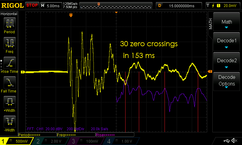
Midterm - Week 12
This week, we were tasked with further planning our final, listing and planning outstanding work. I've compiled the entire process in a table format for your convenience.| task | progress | planning |
|---|---|---|
| Procurement of components | 95 % | Week 20 |
| Testing of components, individual control | 70 % | Week 15 |
| Validate and improve hit detection | 50 % | Week 20 |
| Design and manufacturing of the circuit boards | 30 % | Week 18 |
| Bringing together all technical components in the spirit of the spiral design | 20 % | Week 18 |
| Re-milling of the top and bottom plates (from thinner material for better vibration transfer) | 0 % | Week 15 |
| Training for the Fab25 | 0 % | Week 20-24 |
| Assembly of the housing with all the bells and whistles | 0 % | Week 18 |
Further developments - Week 13
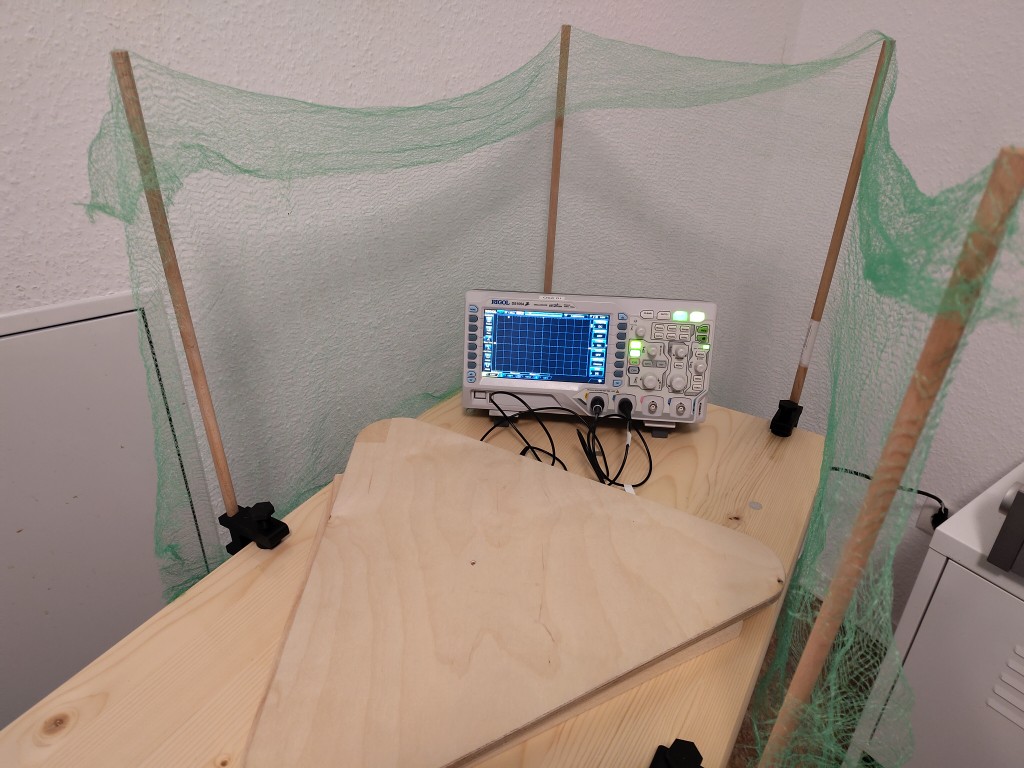
You can probably imagine that during testing, a ball might occasionally bounce or even bounce off the edge of the cup. This naturally adds up with the increasing number of tests, so, frustrated, I finally decided to create a better test environment. Therefore, I present this wonderful, not yet fully assembled safety net. The context in which I initially used it was to test how different sized piezo sensors behave in terms of signal output. All of this can be seen in the entertaining slide show. The result wasn't entirely satisfactory; my favorite is still a different sensor.The clamps for the round bars are a custom design that you can download below.
Re-Milling my plates - Week 14
One result of the previous tests was that I had indulged in the not illogical illusion that a thinner board would be more advantageous. For this reason, I milled both wooden boards again from 9 mm thick plywood.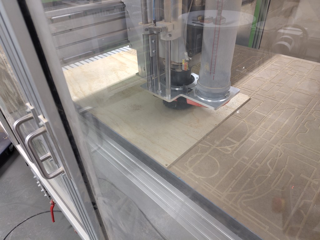
During post-processing, I rounded off the edges with a hand router and then sanded everything finely. Unfortunately, I don't have any dedicated images.
Procrastination - Week 16
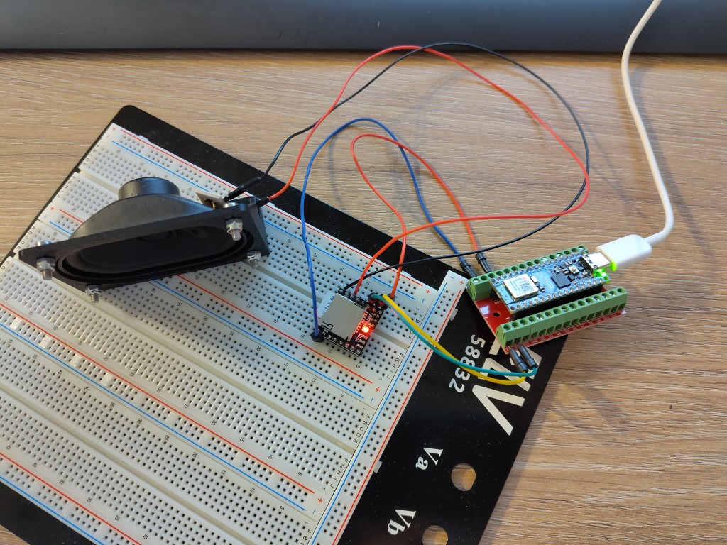
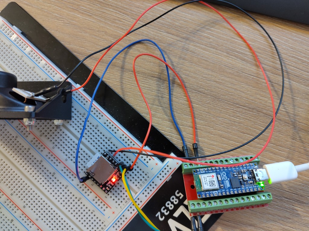
For me personally, week 16 was a job creation measure. I was forced to give myself the time to think about all the possible features my final project could have. That wasn't good.Even though I set it on Spiral 3, the idea of integrating music hasn't left me since. So I've been exploring the topic, grabbed a DF Player Mini, and gotten some suitable passive speakers. You can see it here, all the time; I'm not mentioning how many hours of other kinds of procrastination I've invested. Here's the origin of the theme song, which Kerstin, in her role as a DJ, inspired me to use while working together.
Of course, in order to fit the speaker into my setup, I needed a mount, which I quickly designed and printed.

Finishing the top - Week 17 & 18
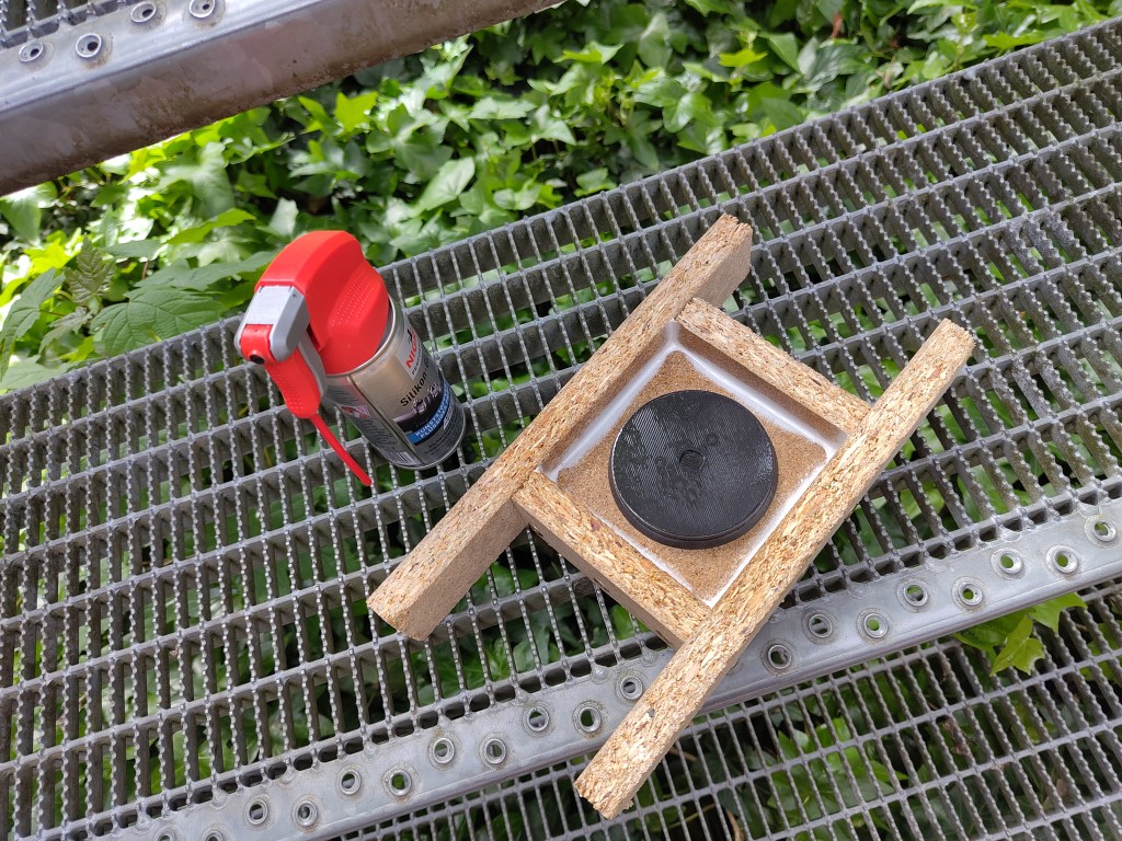
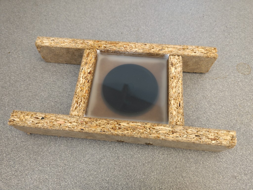
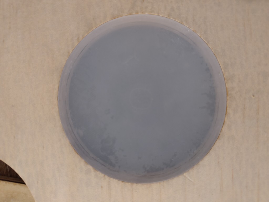
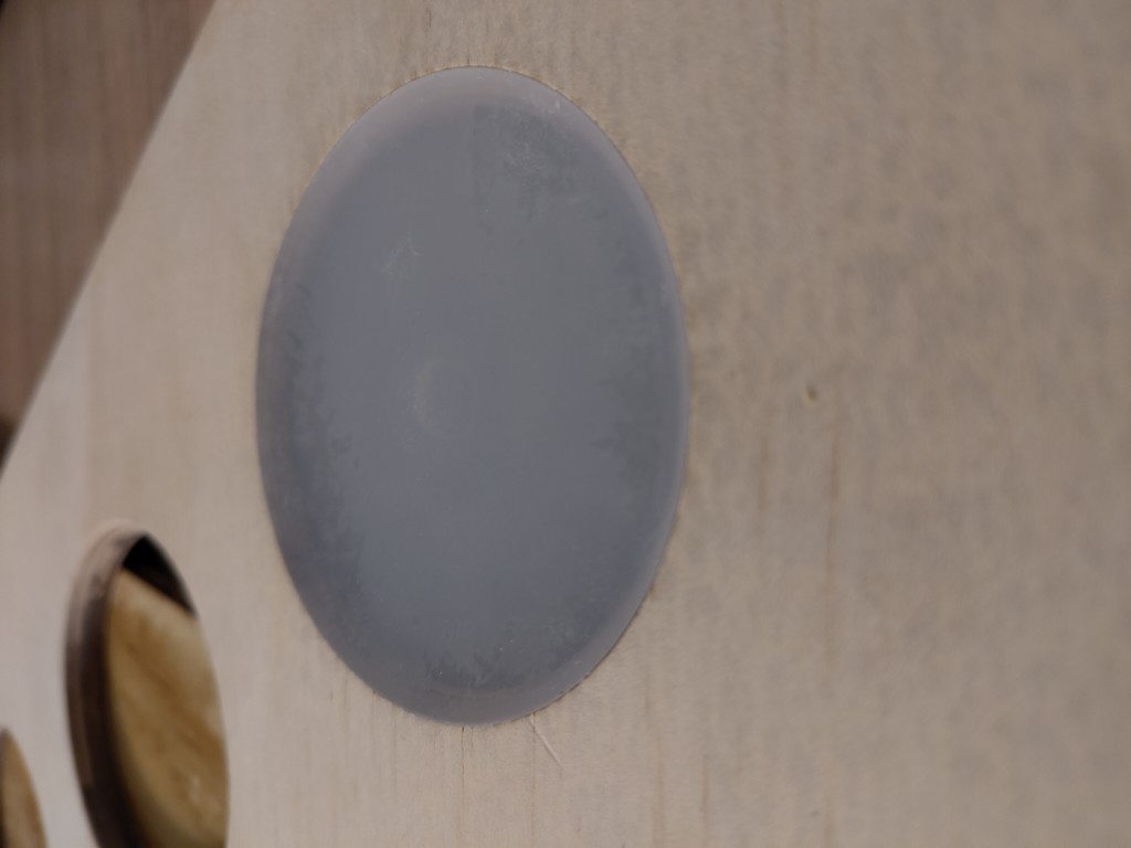
As you can see, I'm having trouble testing my application scenario with the top plate due to the cutouts. So, the next step was to think about how to fill them. I quickly turned to epoxy resin, but I didn't want to simply pour the plate, potentially allowing me to replace parts later without having to replace the entire top plate. So I thought about casting inserts that I could place into my cutouts. To ensure that they hold, and to improve the casting process, I need bevels, which is why I came up with the following design for the inserts.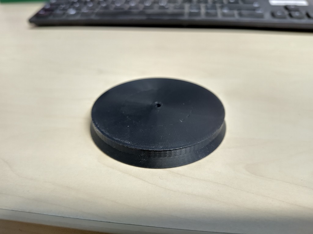
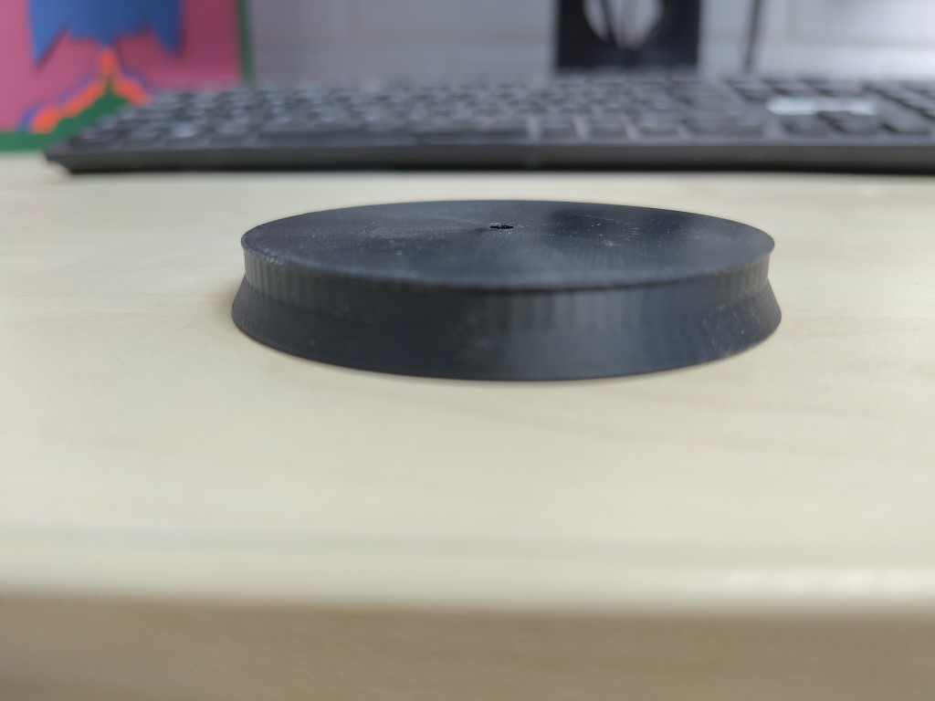
You can still see a hole in the middle. At this point, I was still optimistic about getting my system to work with photodiodes. Later, I realized that wasn't the case. I also tried IR photodetectors, which were equally unsuccessful. This led me back to my first solution, the photoresistor, and forced me to switch to a new design. This ultimately led me to the following design: the 3D print corresponds to the positive part that I will later cast from epoxy resin.
How did I get there?
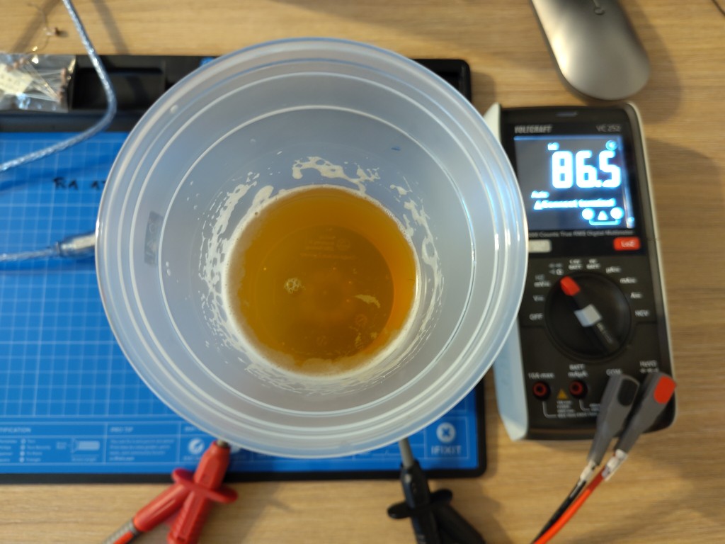
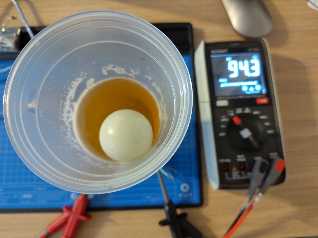
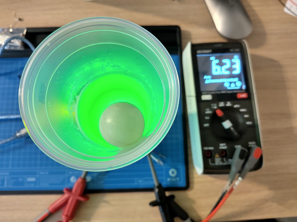
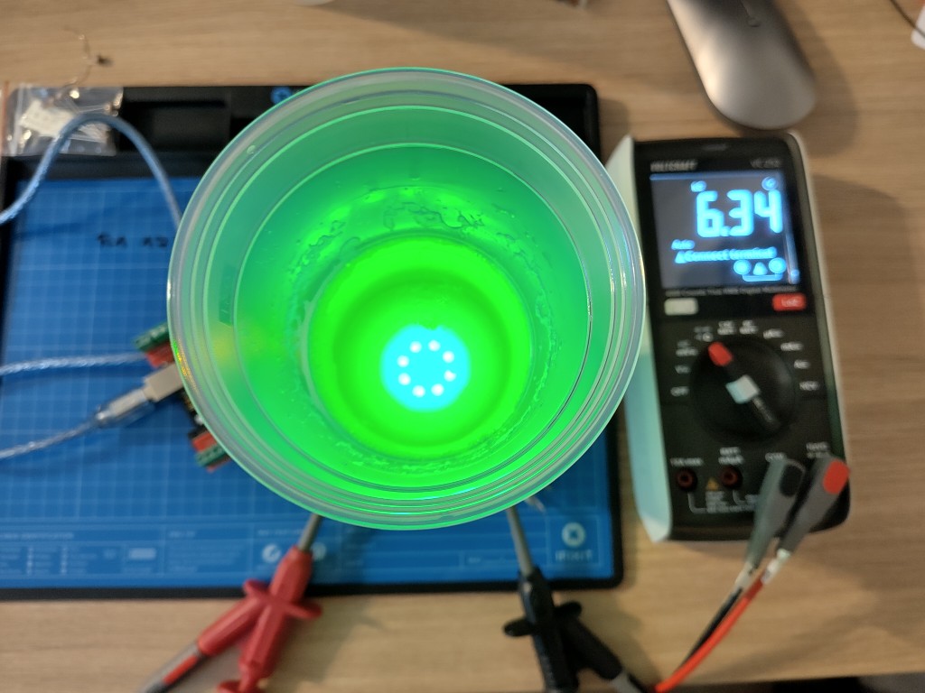
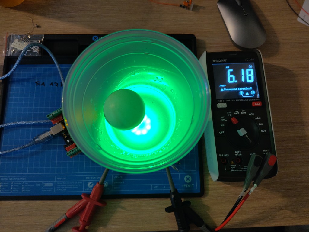
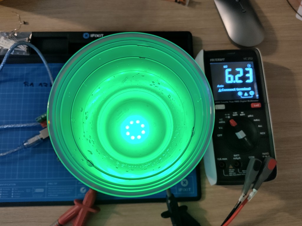
As mentioned, I conducted extensive breadboard tests with my sensors before finalizing or manufacturing them. These were very frustrating tests for a long time. Because frustration doesn't take photos, there's a small gap here as well. The photodiode I used for testing only generated an extremely small photocurrent and reacted particularly to strong brightness, not, as in my case, to a slight change in brightness caused by a ball falling into the cup. The IR decoder sounded promising, but unfortunately, the vast majority of the radiation was already reflected by the underside of the cup, so I couldn't achieve any measurable difference with the ball. Measuring with IR would have freed me from the ambient light variable, which would have been nice.Now you're reading this because I've chosen the photoresistor. It's cheap, after all. I experimented with it a bit. To stay in the style of my very early beer pong table, I'd like to illuminate the cups from below. For this, I had also acquired LED rings in advance, which are also of the WS2812b type. To see how they work and behave, I built a simple test scenario using 3D printing and performed the following test.
This meant I knew what fit I needed on my future underside so I could continue with the casting.
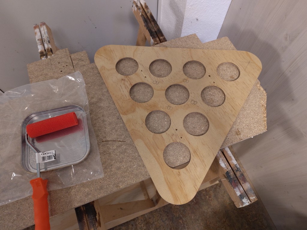
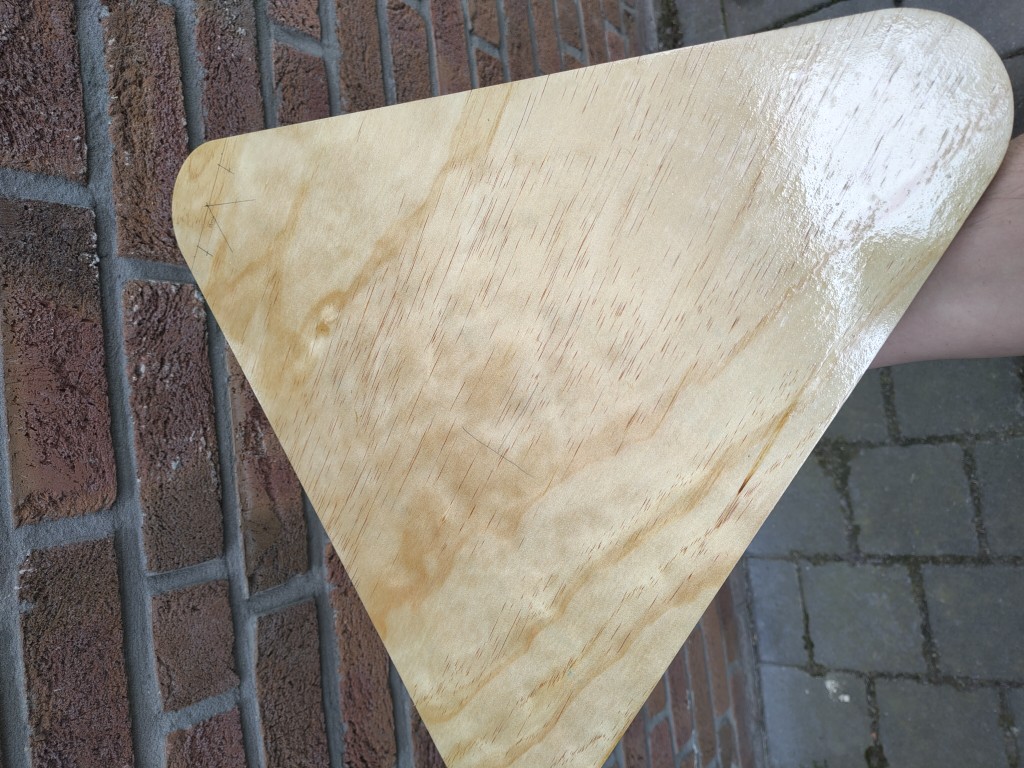
In addition to the inserts, I obviously also need to finish my milled wood, so I decided to use epoxy resin here as well, so I could possibly bond the plate and inserts with it later. I tested the interior surfaces to see how the standard dosage of color for the epoxy resin works. You can see that I have a little white in there, which doesn't match what I want to achieve on the top, so I adjusted the dosage accordingly without any effect
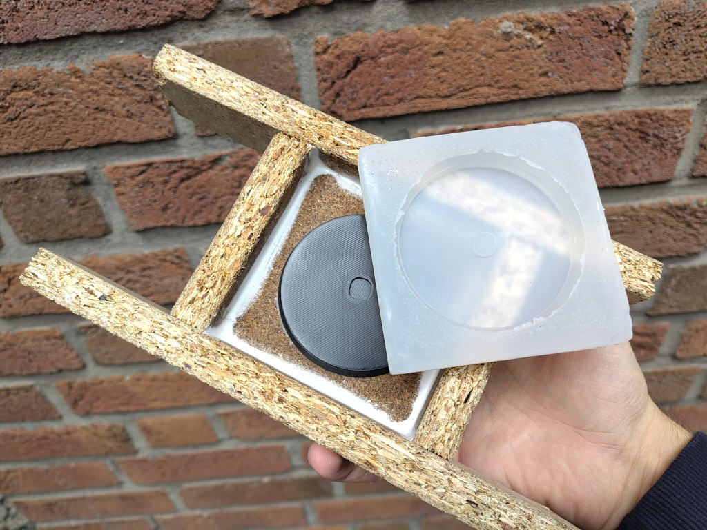
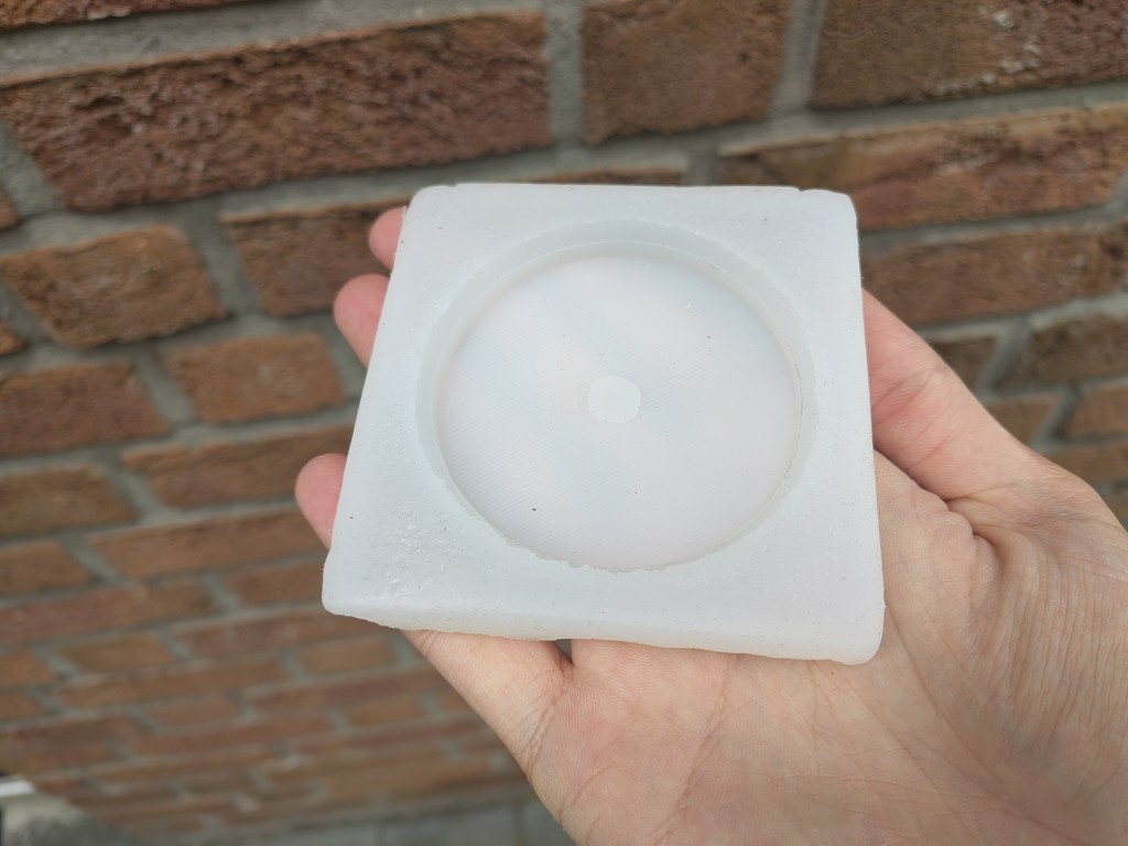
Molding and Casting - Week 18 & 19
Here's just a brief overview of the mold making process, based on the slideshow below. Unfortunately, because I didn't have any non-food-grade silicone available in the lab, I had to use some of my food-grade material for the mold. However, considering I only needed about 80 ml for the mold, the whole thing is more than manageable.
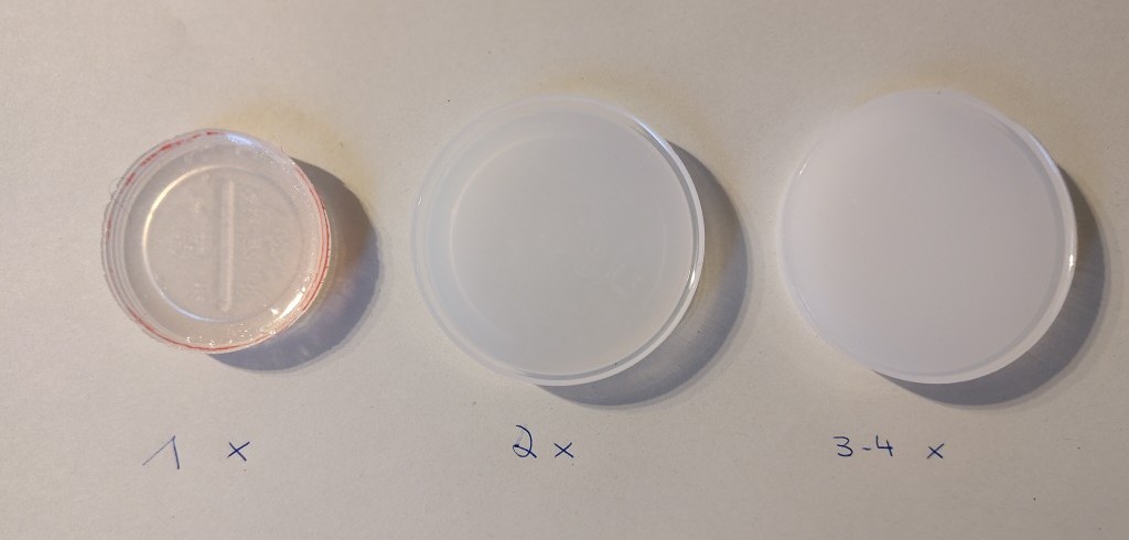
I conducted various tests with the epoxy resin. Because I wanted to make the epoxy resin milky white, I also ordered a matching liquid UV white colorant. From left to right, I made three test pours in plastic cups. On the left is the recommended dosage, in the middle is double the dosage, and on the right, given that I later reduced the dosage to smaller quantities, I used something between three and four times the amount of colorant.
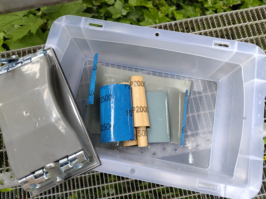
Unfortunately, the epoxy resin castings have become unsightly curled at the edges due to adhesion. The following slideshow shows the wet sanding that all casts had to undergo. I gradually worked my way up to 7000 grit.
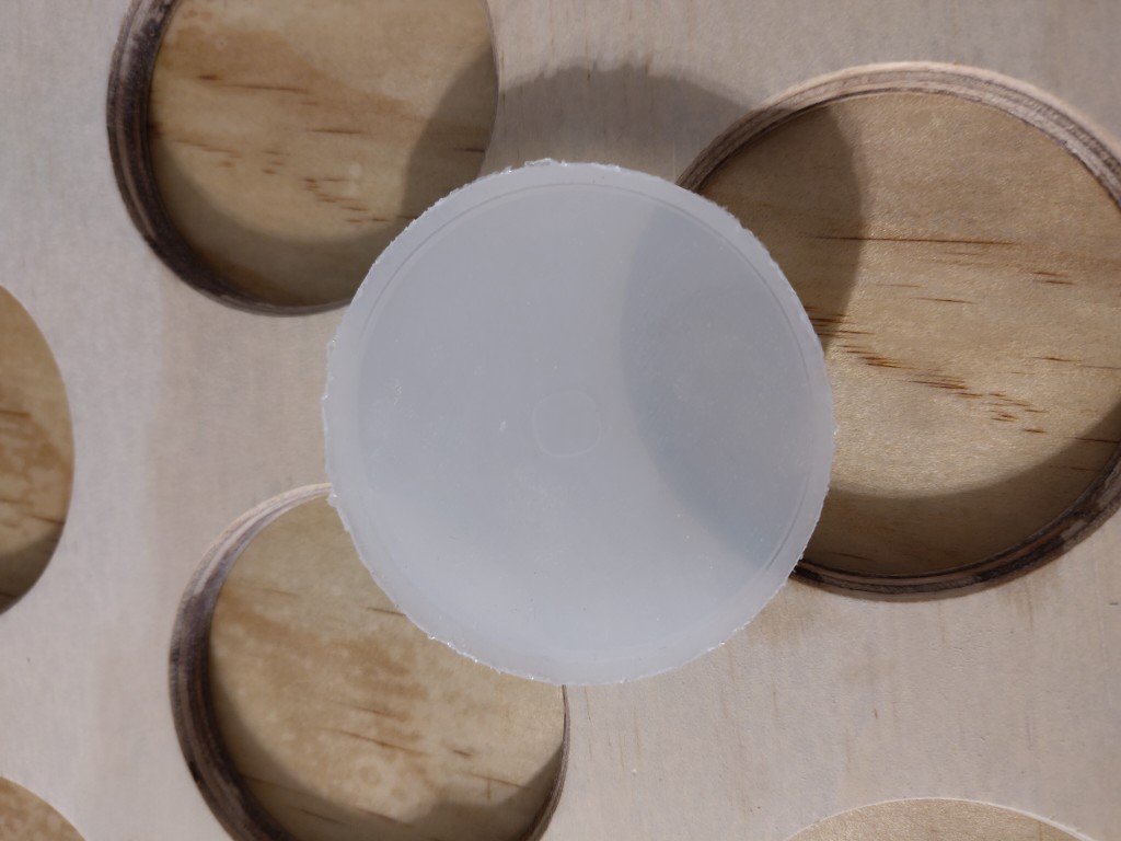
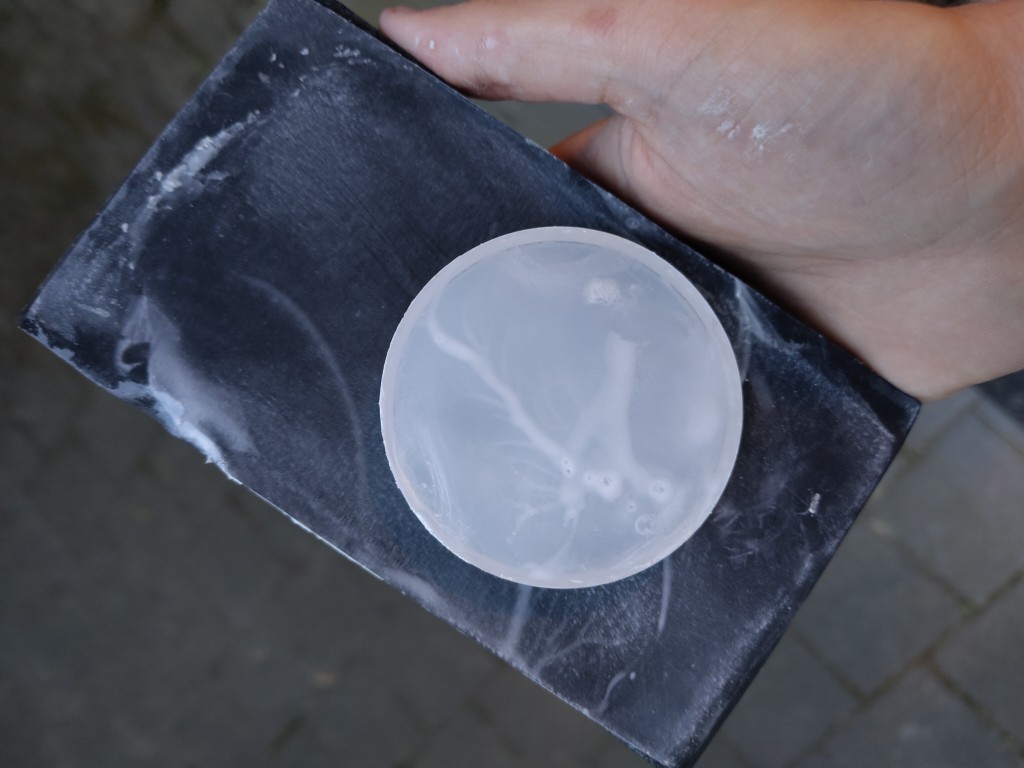
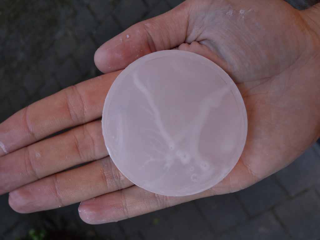
Because I couldn't and didn't want to completely sand away the slight upward curve caused by the adhesion, because the height and thus the fit would have been worse otherwise, I unfortunately didn't achieve an optimal surface finish here. You can see that not all parts of the casting could be reached with the sandpaper.
To bond the casts to my plate, I ultimately decided against epoxy resin and opted for acrylic, because I hope that this will potentially make it easier to remove later if I come to the conclusion that I should replace something.
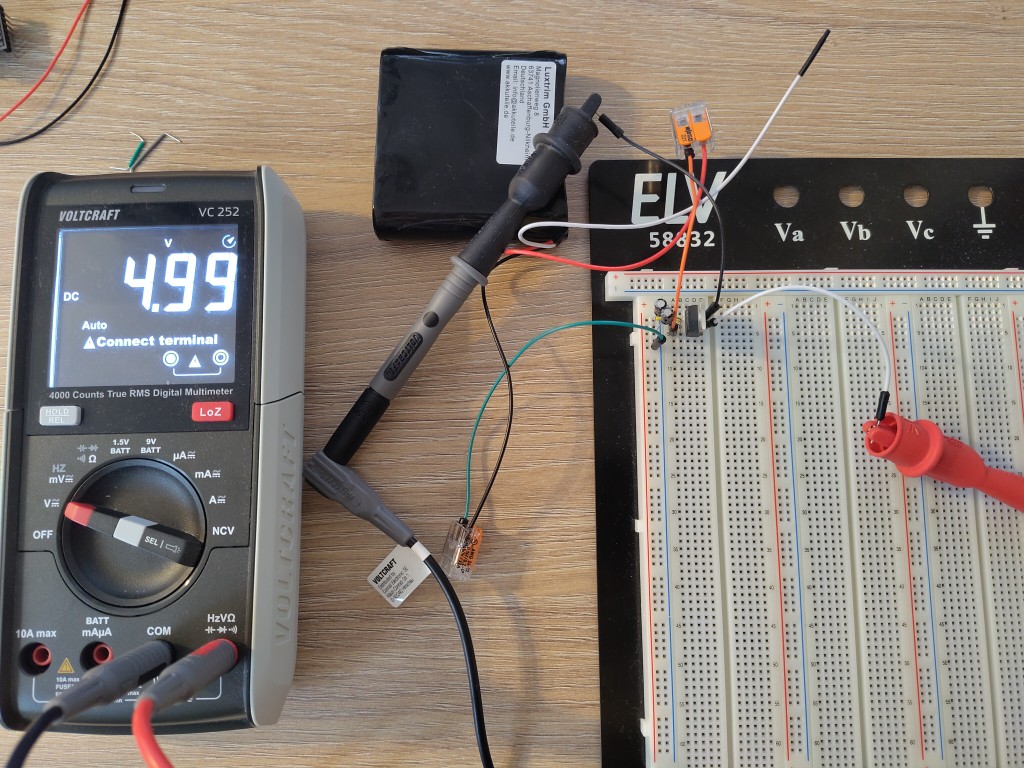
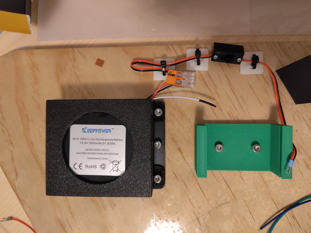
Electronics
To be more confident with the circuits I was building, I tested all the relevant components on the breadboard beforehand, allowing me to identify any errors at this stage. The result was experiments with the battery and my DC-DC converter, my speaker including the DFPlayer Mini, the piezo sensors, photoresistors (including resistor dividers!), and, of course, my LEDs. Some impressions of these tests can be found in the following slideshow.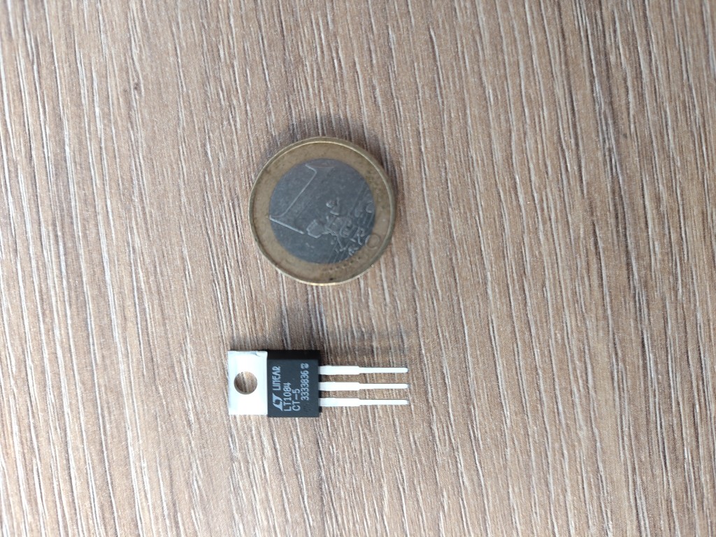
photoresistors
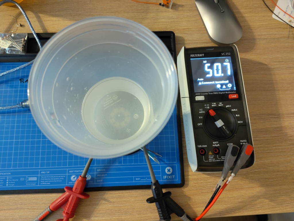
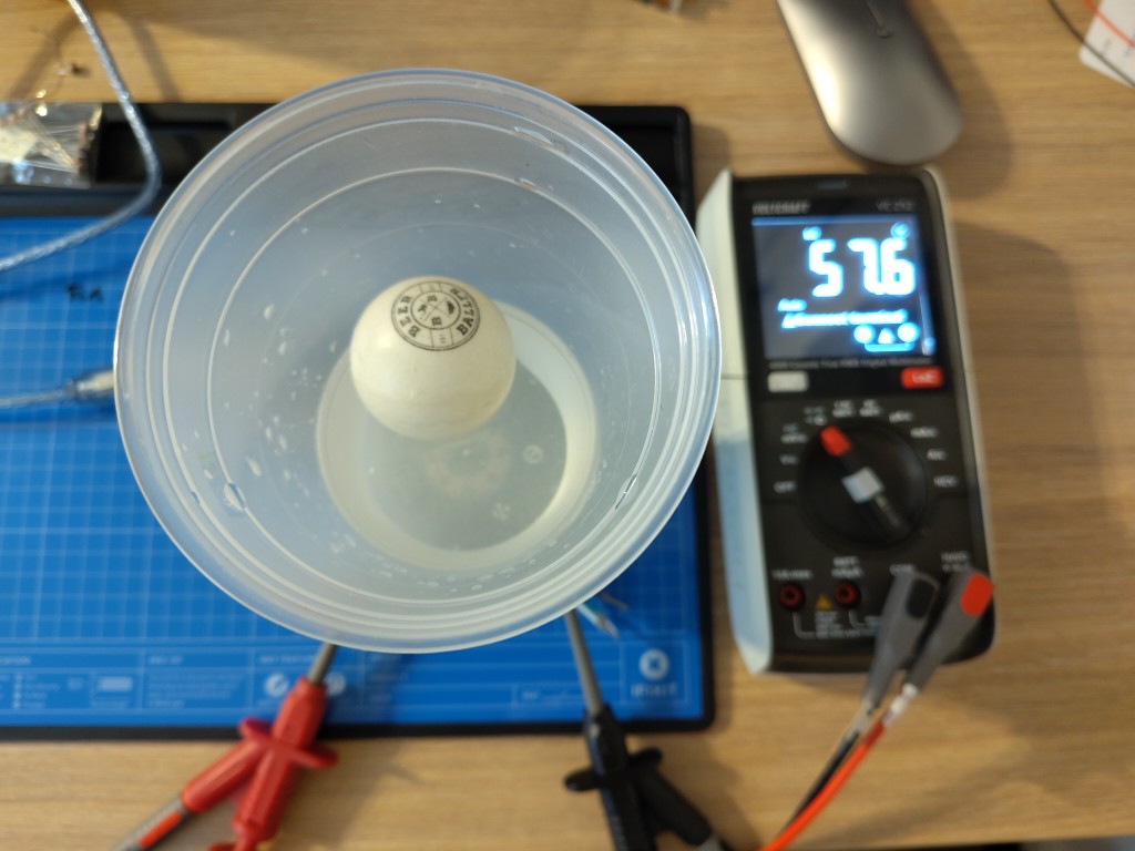
Regarding the photoresistors, I obtained a variety of them and measured their resistance in daylight. Based on these measurements, I divided them into sections and then examined them in more detail under application conditions, as shown in the slideshow. Because this would have exceeded the scope of the photo, I have documented the results in a table.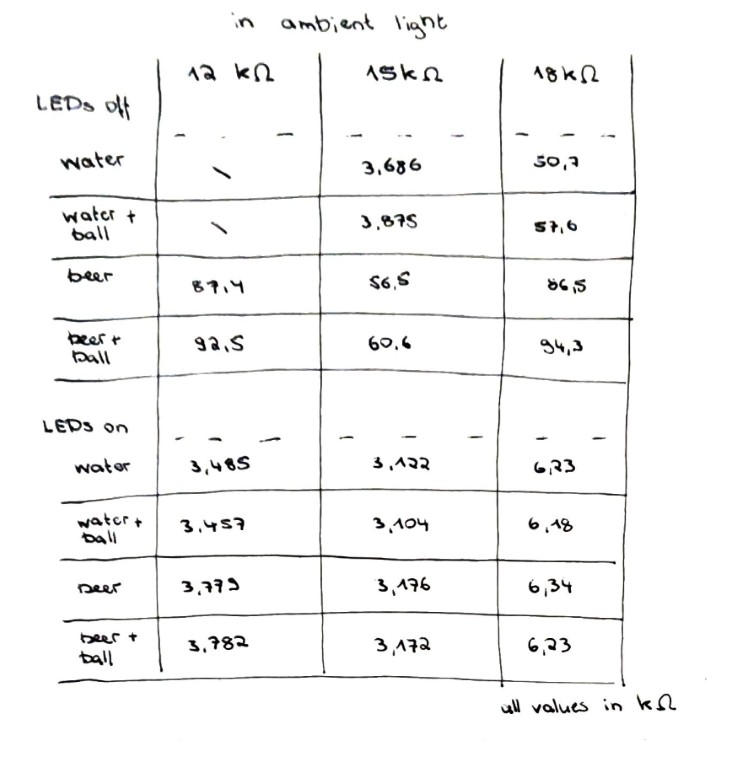
piezo sensors
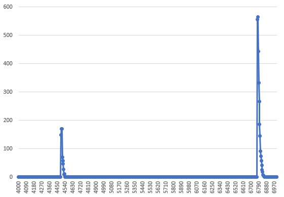
Images 3 to 5 of the previous slideshow show my measurement setup for the digitized measurement with the piezo sensors. Due to time constraints, I decided not to develop my own signal processing based on the sensors I had previously tested, which would have provided me with more information such as zero crossings and frequencies. I based my setup on a commonly available piezo sensor and recorded the values from the serial monitor using the PuTTY software. In my opinion, you can find excellent instructions for doing this yourself here. I created the following plot in Excel from the data recorded every 5 ms. The first plot shows two cups being hit; in the second, the balls each landed on the edge of the cups.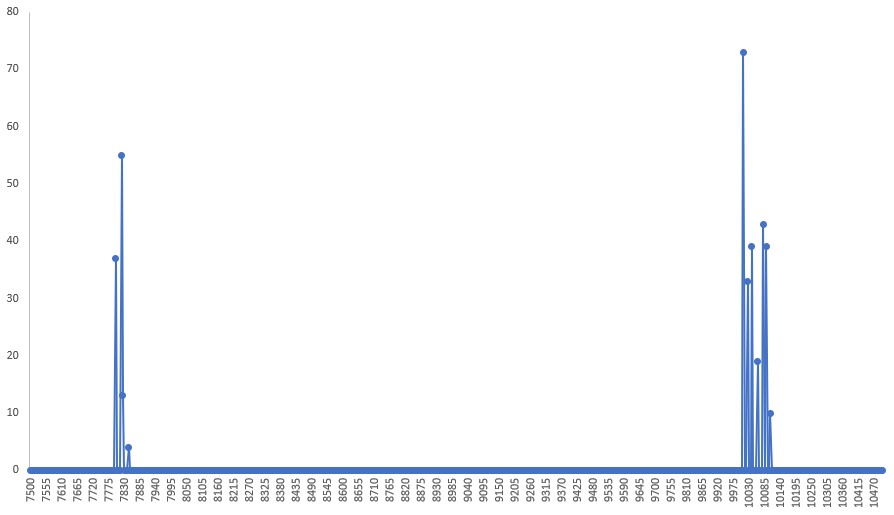
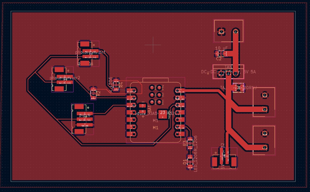
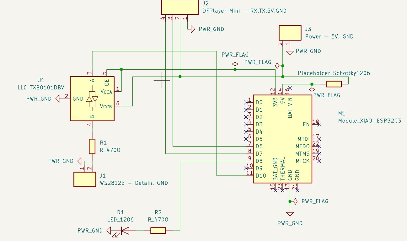
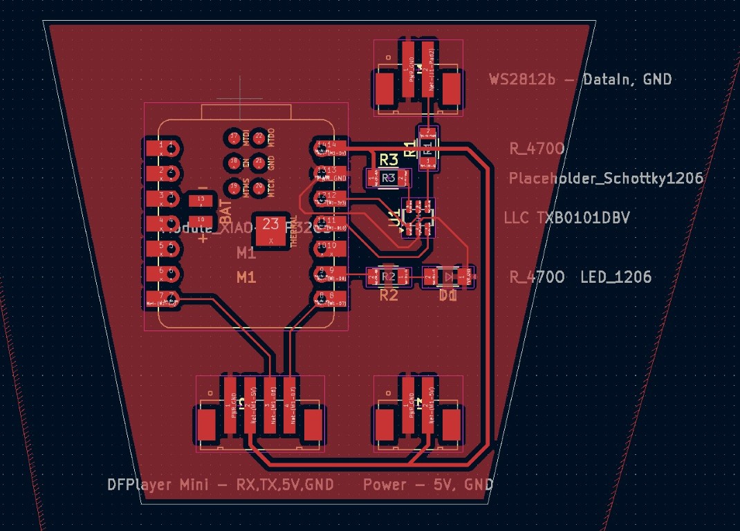
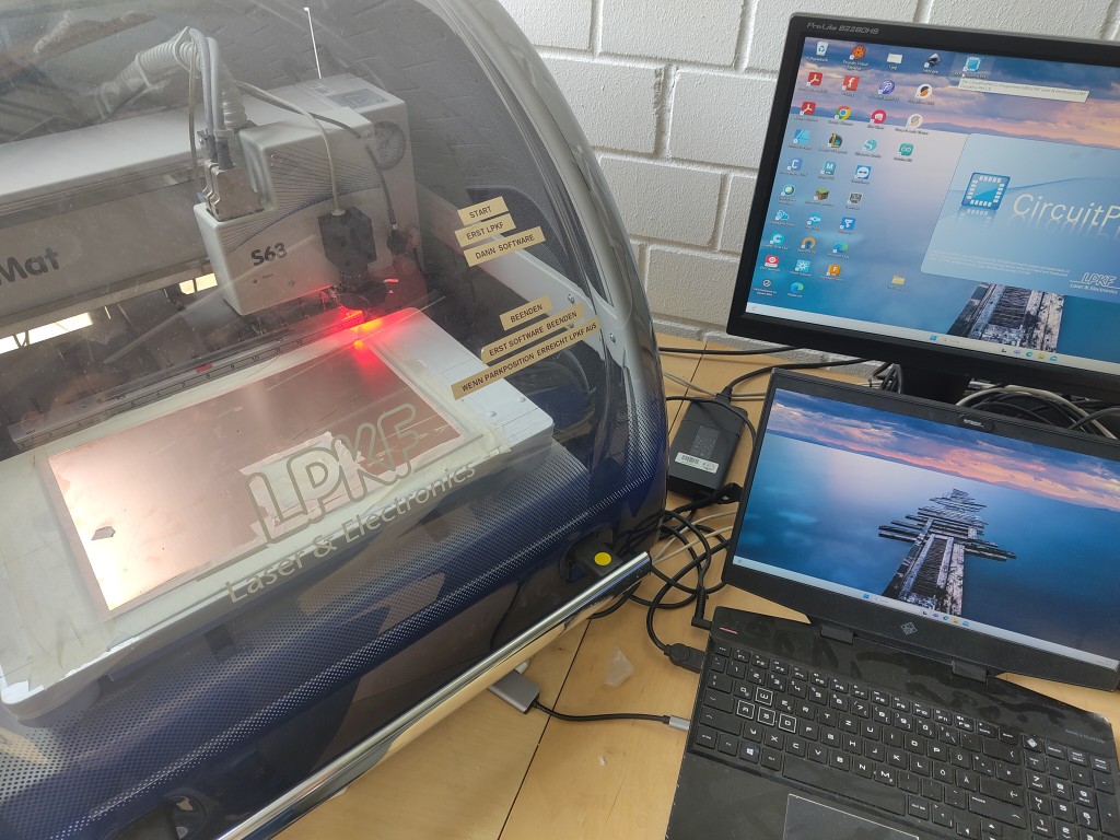
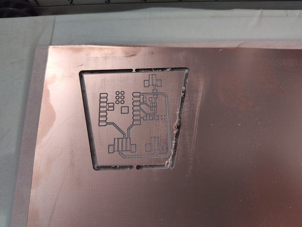
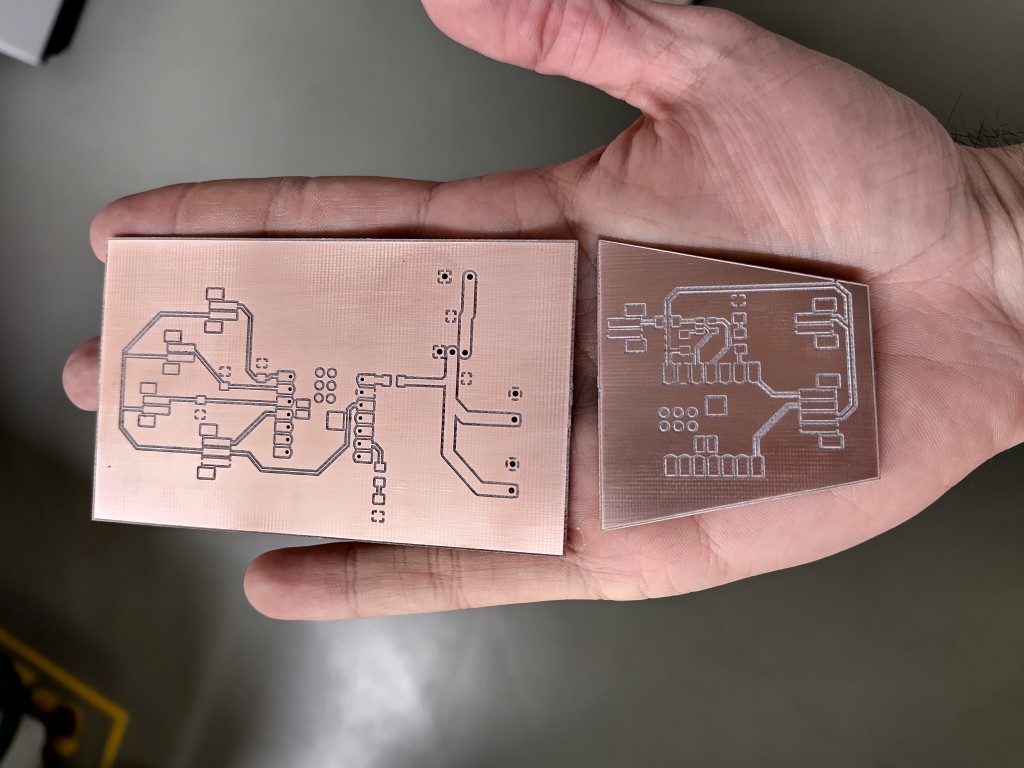
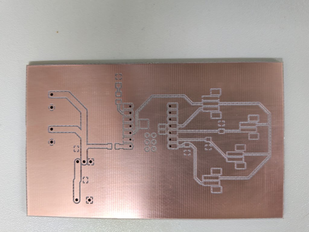
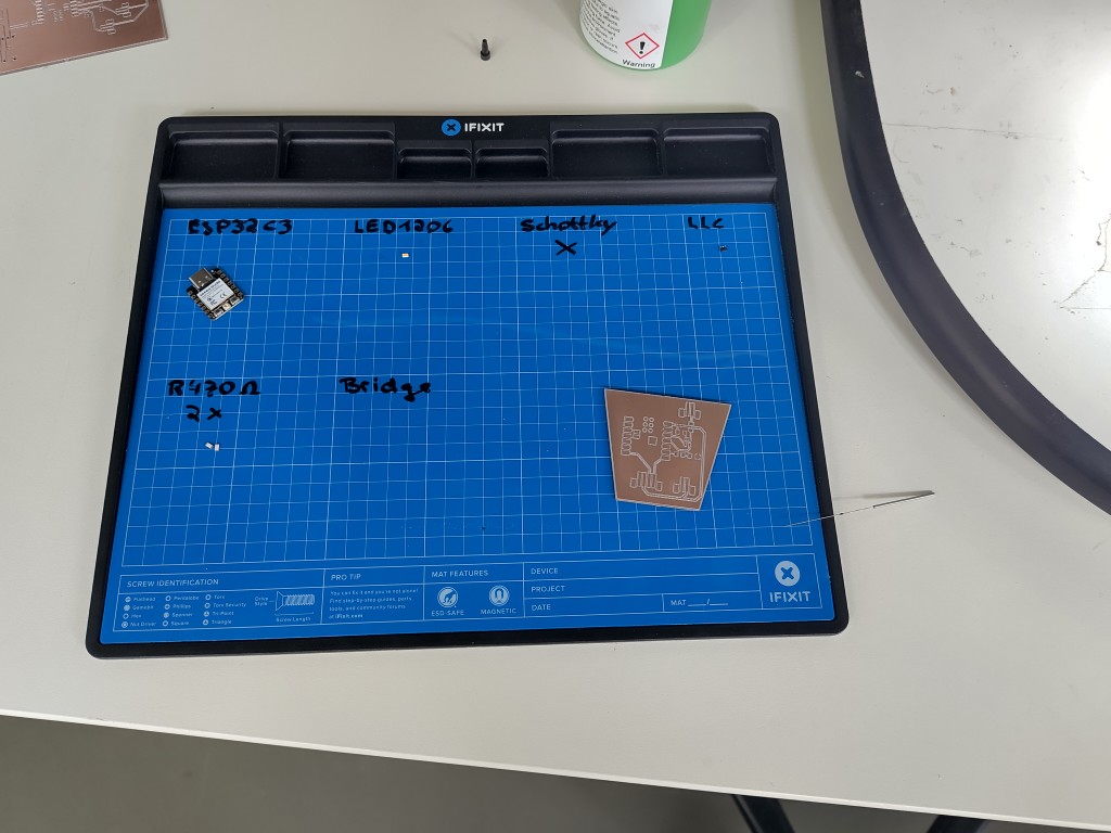
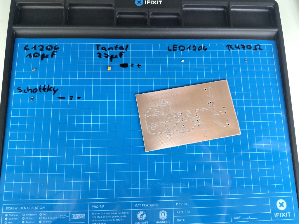
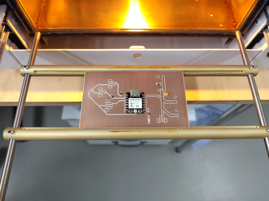
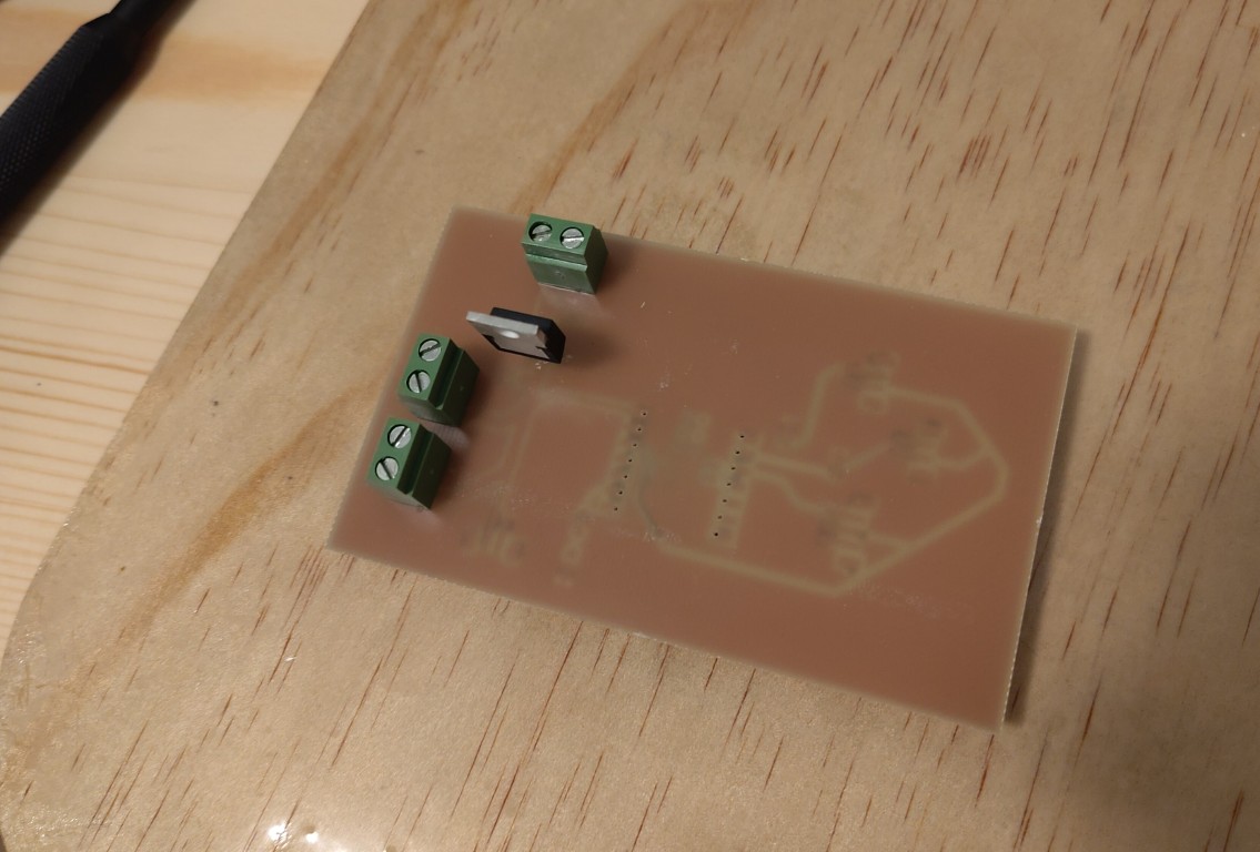
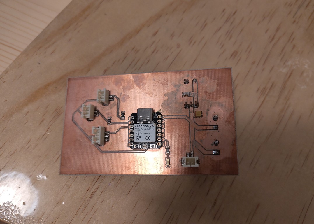
Electronic Production
As in previous weeks, all the electronics are useless if we don't have them in our hands at the end. This was also the case with the finale. Based on the previous breadboard tests, I designed and manufactured two boards that will communicate with each other via ESP-Now as Teacher and Student. The Teacher will process the sensor inputs and, based on their evaluation, trigger outputs in the form of light and sound from the Student. It would be too extensive to describe everything in detail, so here are just a few impressions from the ideation to the finished hardware.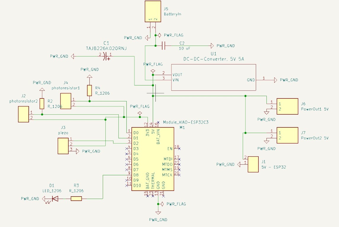
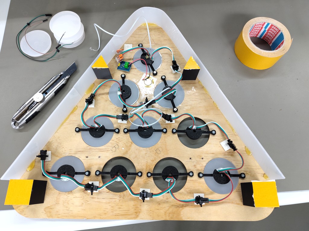
Assembly
With the electronics in my hands, the main task was to get everything together. This meant assembling the components and securely storing them in my prototype. There are also some impressions of this in the form of a slideshow. As previously announced, I primarily relied on 3D printing for the internal assembly of my components. I left 5 mm holes in the cases and used them to screw the mounts into screw-in nuts that I inserted into my wooden board. Alternatively, and in retrospect, I would simply recommend double-sided tape; the board is a bit thin for screw-in nuts.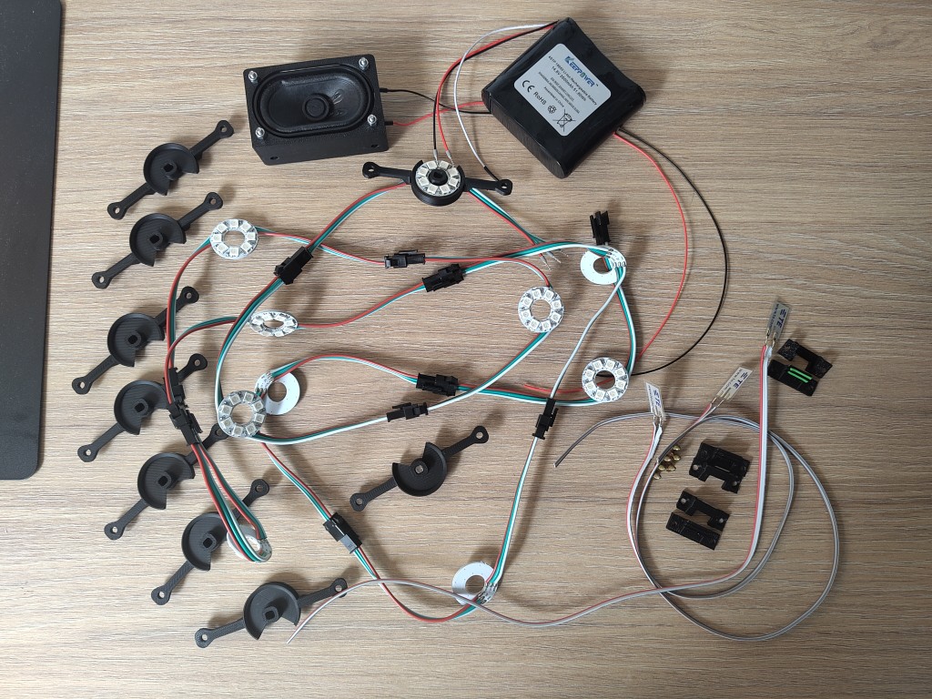
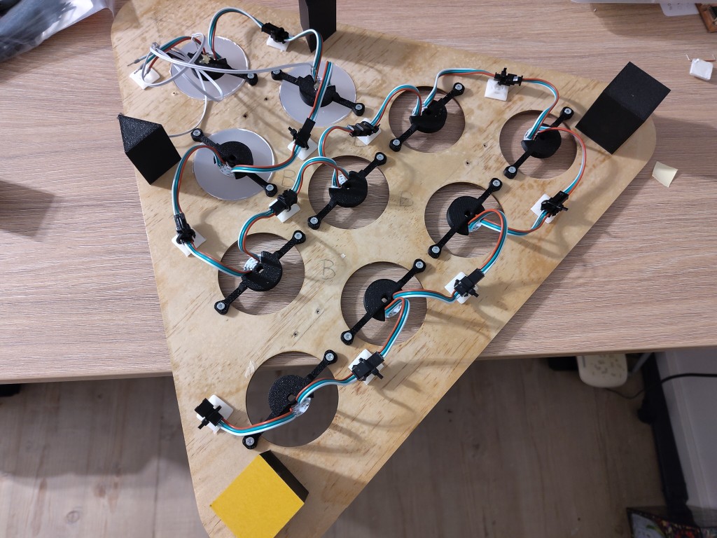
Here are two short video clips showing the assembly and an assembled version, respectively. The cable connection for the piezo sensor is missing. This was not needed for the test I recorded. Based on the measurement recordings found above under the piezo sensor, the information gained from this commercially available version is unfortunately limited.
Programming
The programming, in particular, brought together content from previous weeks, so it was quite grateful. The following code is the one I used for my functionality tests.teacher
#include <esp_now.h>
#include <WiFi.h>


int LDR1 = A0; // analog pin for ldr1
int LDR2 = A1; // analog pin for ldr2
int sensorValue1 = 0; // variable for sensor value 1
int sensorValue2 = 0; // variable for sensor value 2

int STATUS_LED = 8;

uint8_t broadcastAddress[] = { 0xb0, 0x81, 0x84, 0x05, 0xee, 0x4c };

// setting the structure for data transfer
struct Message {
  int action;
};

// Create an instance of the message structure
Message message;
// Defines information about the ESP-NOW peer (the receiver)
esp_now_peer_info_t peerInfo;
// Callback function that is called when a message has been sent
void OnDataSent(const uint8_t *mac_addr, esp_now_send_status_t status) {
  Serial.println(status == ESP_NOW_SEND_SUCCESS ? "successfull!" : "error!");
}

void setup() {
  Serial.begin(9600);
  pinMode(STATUS_LED, OUTPUT);

  WiFi.mode(WIFI_STA); // Set Wi-Fi mode to Station (prevents interference)
  // Initialize ESP-NOW and check if the initialization is successful
  if (esp_now_init() != ESP_OK) {
    Serial.println("Error initializing ESP-NOW");
    return;
  }

  // Register the callback function for the shipping status
  esp_now_register_send_cb(OnDataSent);
  // Add the destination address and other settings to the peer info structure
  memcpy(peerInfo.peer_addr, broadcastAddress, 6); // MAC address of the recipient
  peerInfo.channel = 0; // Use the default channel
  peerInfo.encrypt = false; // No encryption
  // Add the peer to the ESP-NOW peer list
  if (esp_now_add_peer(&peerInfo) != ESP_OK) {
    Serial.println("Failed to add peer");
    return;
  }

}

void loop() {
 readSensor1();
 readSensor2();


 if(sensorValue1 <= 570){
  /*I wouldn't recommend doing anything like this here; the value is highly dependent on the liquid used,
  the fill level in the cup, and the ambient conditions. Calibration would be useful, but the time from the
  cup onward is always displayed on the device after power-up, so it would be best to have the user perform
  a calibration via the GUI. Unfortunately, the drop in the photoresistor value with a ball in the cup also
  varies in magnitude, both absolutely and in percentage terms, which makes it very difficult to work with.*/

  message.action = 1;
  esp_now_send(peerInfo.peer_addr, (uint8_t *)&message, sizeof(message));
  digitalWrite(STATUS_LED, HIGH);
  delay(200);
  digitalWrite(STATUS_LED, LOW);
  }

 if(sensorValue2 <= 570){
  message.action = 2;
  esp_now_send(peerInfo.peer_addr, (uint8_t *)&message, sizeof(message));
  digitalWrite(STATUS_LED, HIGH);
  delay(200);
  digitalWrite(STATUS_LED, LOW);
  }
}

void readSensor1() {
  sensorValue1 =analogRead(LDR1);
  }

void readSensor2() {
  sensorValue2 =analogRead(LDR2);
  }
student
#include <DFRobotDFPlayerMini.h>
#include <Adafruit_NeoPixel.h>
#include <esp_now.h>
#include <WiFi.h>

DFRobotDFPlayerMini dfplayer;

#define LED_COUNT 80 // 10 led rings with 8 leds each
const int LED_PIN  = 10; // data pin for WS2812b
const int LED_STATUS = 8; // led to indicate whenever a message is received

Adafruit_NeoPixel strip(LED_COUNT, LED_PIN, NEO_GRB + NEO_KHZ800);


// Structure for the received data
struct Message {
  int action;
};
// Create an instance of the message structure
Message message;
// Callback function that is called when data is received
void OnDataRecv(const uint8_t *mac, const uint8_t *incomingData, int len) {
  // Copy the received data into the local message structure
  memcpy(&message, incomingData, sizeof(message));

  if(message.action == 1){
    for(int i=0; i<8; i++) { // For each pixel in strip...
    strip.setPixelColor(i, 100,0,0);         //  set pixel's color to match the rest
    strip.show();                          //  update strip
    delay(100);         }                  //  same delay as above
	// dfplayer.play(2);                   // here you could make use of different sounds, which in my case hasn't yet been the case
   }

  else if(message.action ==2){
    for(int i=8; i<16; i++) { // For each pixel in strip...
    strip.setPixelColor(i, 100,0,0);         //  set pixel's color to match the rest
    strip.show();                          //  update strip
    delay(100);         }                  // same delay as above
	// dfplayer.play(2);                   // here you could make use of different sounds, which in my case hasn't yet been the case
   }

  digitalWrite(LED_STATUS, HIGH);
  delay(200);
  digitalWrite(LED_STATUS, LOW);
}


void setup() {
  Serial.begin(9600);

  HardwareSerial& dfSerial = Serial1;
  dfSerial.begin(9600);

  if(!dfplayer.begin(dfSerial)) {
    Serial.println(F("DFPlayer init failed!")); // error message via serial monitor - debugging via personal computer

    while(true);
    }
  Serial.println("DFPlayer ready");


  WiFi.mode(WIFI_STA); // Set Wi-Fi mode to Station (prevents interference)
  // Initialize ESP-NOW and check if the initialization is successful
  if (esp_now_init() != ESP_OK) {
    Serial.println("Error initializing ESP-NOW");
    return;
  }
  // Register the callback function for received data
  esp_now_register_recv_cb(esp_now_recv_cb_t(OnDataRecv));


    strip.begin();           // initialize NeoPixel strip object (REQUIRED)
    strip.show();            // turn OFF all pixels
    strip.setBrightness(50); // set brightness to about 1/5 (max = 255) because of limitations with the battery management system - do it different than me!

    for(int i=16; i<strip.numPixels(); i++) { // set leds 17 to 80 (eight cups, that i can't detect in this setup, so they are always illuminated
    strip.setPixelColor(i, 100,0,0);         //  set pixel's color to red
    strip.show();                          //  update strip
    delay(100);         }                  //  turn on the lights with a delay, for a cooler effect


  dfplayer.volume(30); // 30 is maximum
  dfplayer.outputDevice(DFPLAYER_DEVICE_SD);
  dfplayer.play(1); // play 0001.mp4 from the sd - in my case booing
}

void loop() {
  // nothing to show
}
It's far from complete, just like this project as a whole.
Overall, I'm not satisfied with the result, but I'm a lot wiser. Many of the lessons learned were essential to achieving better results in the future, but at the same time, it requires more time and less time pressure. This isn't the end, even if my journey with the FabAcademy concludes with these lines. Thank you for your attention!
Bill of Materials
| quantity | material | dimensions | costs | link |
|---|---|---|---|---|
| 1 | plywood, 9 mm | 100 x 50 cm | 20 € | |
| 1 | epoxy resin | < 0.75 l | 20 € | |
| 1 | casting silicone | < 0.2 l | 5 € | |
| 1 | acrylic glass, 4 mm, white opal | 0.25 m² | 8 € | |
| 2 | ESP32C3 XIAO | 7 € | https://www.digikey.de/de/products/detail/seeed-technology-co-ltd/113991054/16652880 | |
| 1 | ribbon cable 0.1 mm², 14 wires | 1 m | 3 € | https://www.digikey.de/de/products/detail/3m/3801-14-100/22532387 |
| 1 | simple cables (red and black) | ~2 m each colour, 0,25 mm² | 2 € | |
| 1 | piezo sensor | 1 € | ||
| 2 | Photoresistor | 0.50 € | ||
| 1 | passive speaker | 7 € | https://www.digikey.de/de/products/detail/visaton-gmbh-co-kg/SC-4-7-ND-8-OHM/9842404 | |
| 1 | DFPlayer Mini | 2 € | https://www.digikey.de/de/products/detail/dfrobot/DFR0299/6588463?s=N4IgTCBcDaICYDMAOAbAhgTwKYCcAEAtgJYB2RIAugL5A | |
| 10 | WS2812b Rings, 8 LEDs | 1 € | https://de.aliexpress.com/item/1005002287819725.html?spm=a2g0o.order_list.order_list_main.35.27c05c5f3owaSZ&gatewayAdapt=glo2deu | |
| 1 | battery, 4x 18650 Li-Ion | 14,8 V, 3500 mAh, 51,80 Wh | 37 € | https://www.akkuteile.de/power-bank-mobile-energie/akkupack/keeppower-4s1p-3500mah-14-8v-li-ion-akkupack-mit-bms-schutz_12031_1035 |
| 1 | power supply, on-board | 5V, 5 A | 13 € | https://www.digikey.de/de/products/detail/analog-devices-inc/LT1084CT-5-PBF/888532 |
| 1 | logic-level-converter | SOT23-6 | 0.50 € | https://www.digikey.de/de/products/detail/texas-instruments/TXB0101DBVR/1534254 |
| many | resistors, capacitors, leds; 1206 | different values | ~ 1 € | |
| 1 | capacitor tentulum | 22 uF | ~ 0.50 € | https://www.digikey.de/de/products/detail/kyocera-avx/TAJB226K020RNJ/563789 |
| 3 | screw terminals | 2 pins | 1 € | https://www.digikey.de/de/products/detail/w%C3%BCrth-elektronik/691137710002/6644051 |
| 4 | JST-XH connection socket and header | 2 pins | € | https://www.digikey.de/de/products/detail/jst-sales-america-inc/02KR-6H-P/2797473, https://www.digikey.de/de/products/detail/jst-sales-america-inc/B2B-PH-SM4-TBT/2137328 |
| 2 | JST-XH connection socket and header | 3 pins | € | https://www.digikey.de/de/products/detail/jst-sales-america-inc/03KR-6H-P/2797474, https://www.digikey.de/de/products/detail/jst-sales-america-inc/B3B-PH-SM4-TBT/768445 |
| 1 | JST-XH connection socket and header | 4 pins | € | https://www.digikey.de/de/products/detail/jst-sales-america-inc/04KR-6H-P/2797475, https://www.digikey.de/de/products/detail/jst-sales-america-inc/B4B-PH-SM4-TBT/2217689 |
| ~ 30 | screw-in nuts | M4x5 | 9 € | https://www.schraubenking-shop.de/M4-x-5mm-Rampa-Muffe-Typ-E-Stahl-verzinkt-P003888 |
| ~ 40 | screws | M4x8 | 2 € | |
| 1 | PLA, black | ~ 200 g, 1,75 mm (depending on the printer) | ~ 5 € | |
| 1 | pcb material (in my case FR4) | ~ 150 cm² | ||
| 1 | hot glue, acrylic, double-sided tape | very little | ... |
Creative Common
With a view to Creative Commons licensing, I have decided to publish my project under the CC BY-NC license in order to keep commercial use open for myself but to generally allow others to create other cool projects with inspiration from my project.