Mechanical Design, Machine Design
This weeks individual assignment:
- design a machine that includes mechanism + actuation + automation + application
- build the mechanical parts and operate it manually
- actuate and automate your machine
- document the group project and your individual contribution
This weeks learnings:
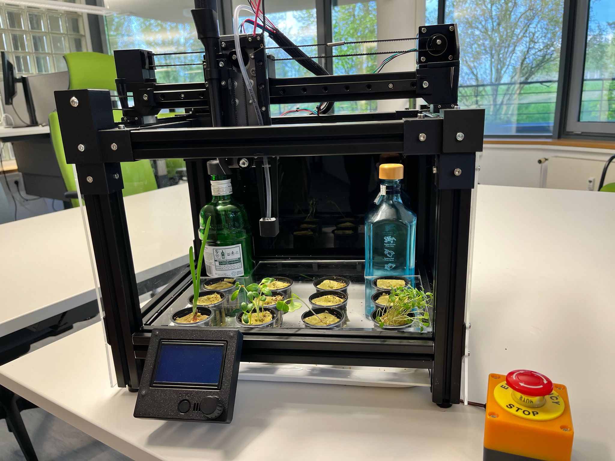
The last two weeks have been incredibly time-consuming, often frustrating, but ultimately very educational. I've only delved into programming to a very limited extent, but otherwise I've dedicated myself to everything else, especially crunching my brain on the engineering of our Z-axis. We've combined a few cool principles, and overall, I think we've created a veritable machine in two weeks. So it's definitely worth taking a closer look, and checking out Kerstin and Julian's site as well, as the machine is the result of the work of us three.
general thoughts, preparation and co-working
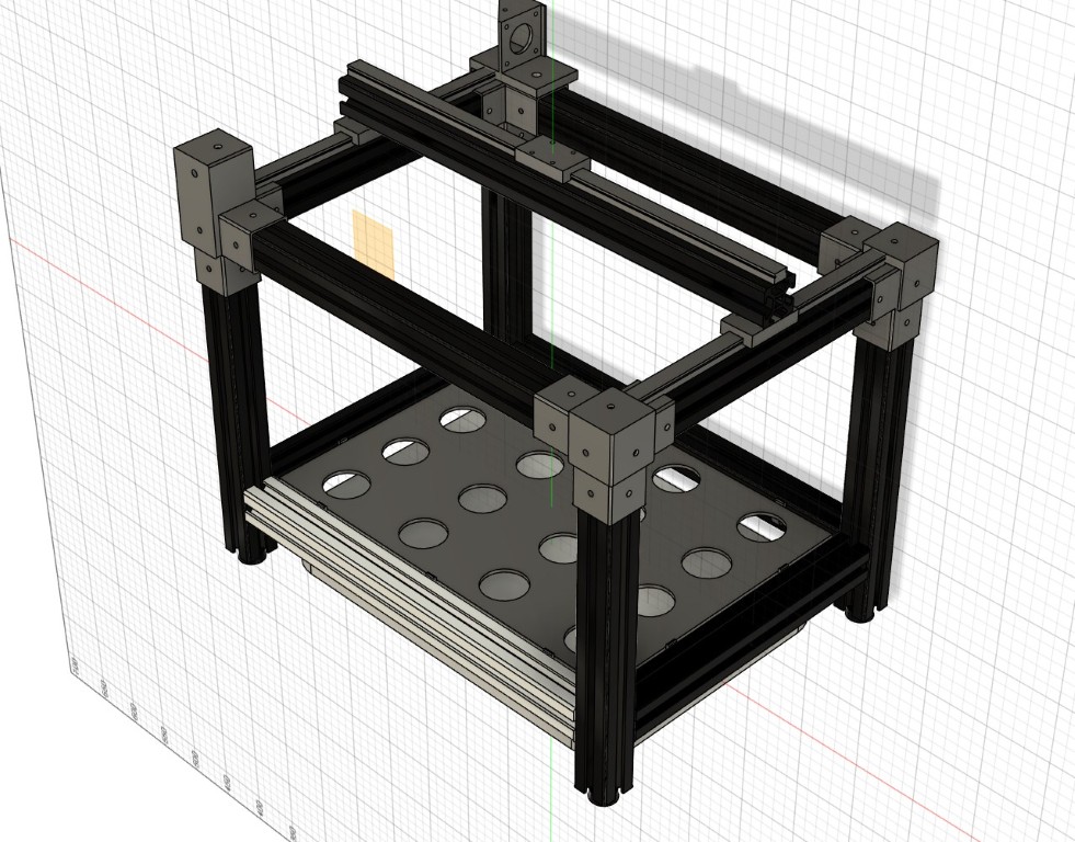
After our initial meeting and the idea for our machine, I began to clarify the relevant technical and mechanical components and, together with Julian, thoroughly thought through, defined, and procured them in advance. We had, or rather, planned to use 3D printing to counteract any additional surprises on our path to a functioning machine. We were able to use some components already in the lab, such as stepper motors, which we wanted to use for all three axes. Further procurements were based on the available materials, and in some cases, this also resulted in restrictions or assumptions for the mechanics. Julian and I opted for linear guides with carriages for the guides, and we want to transmit the motion via the typical GT2 belts that are also used in 3D printers.Overall, the design lived only in our heads for a while, at least to the extent that we were confident that we wouldn't be unpleasantly surprised at the start of the week. In the meantime, it has been transferred to a CAD system in Fusion, despite some of the difficulties we encountered. For these two weeks, I created a test Fusion team in which we work and, for example, recorded procurement lists, thoughts, and protocols in the form of a wiki. Fusion actually offers good opportunities for collaboration here; we haven't regretted the decision.
Manufacturing and assembly of our scaffolding
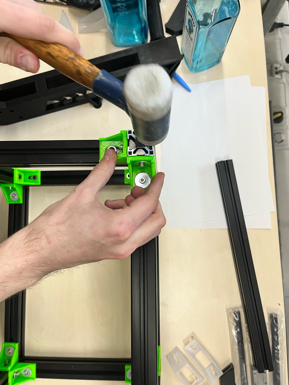
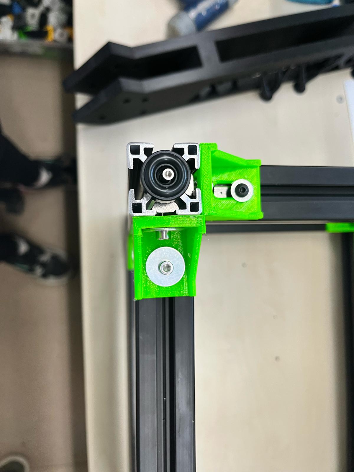
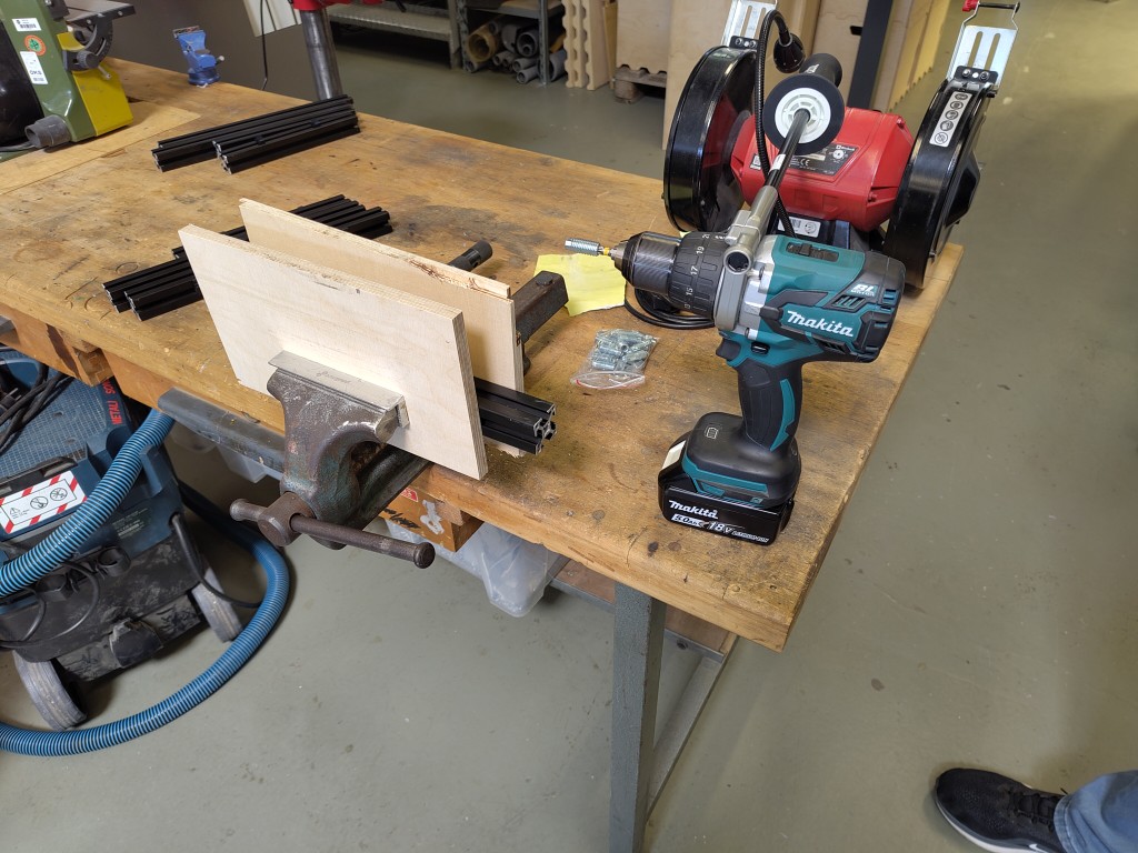
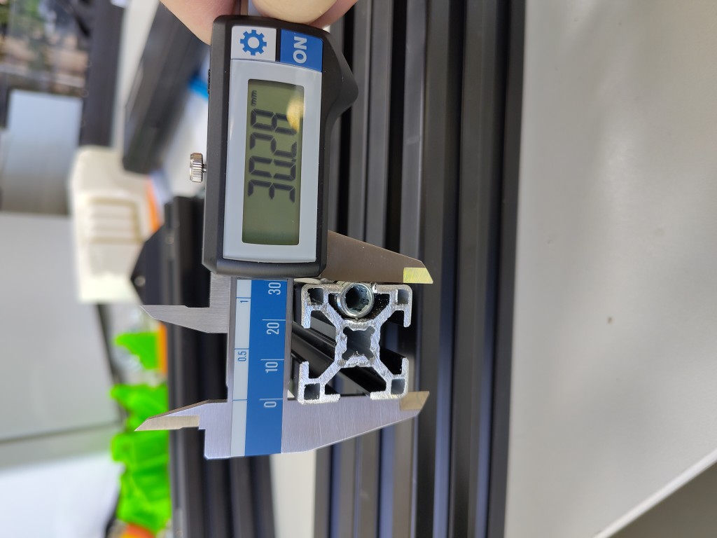
After visualizing the dimensions of our machine using a cardboard prototype, we agreed on the external dimensions. I took this as an opportunity to cut the 30x30 mm aluminum profiles to size and design and 3D print an adapter for the underside of the aluminum profile so that we could attach anti-vibration feet to it. We originally wanted to use automatic connectors to connect the aluminum profiles to each other. When screwing into the lower aluminum profiles, we re-evaluated the whole thing and decided to create and use our own angle constructions for the upper profiles, which we were also able to print. The problem with the automatic connectors is that they bend the aluminum profile slightly, thus deforming it, which would have resulted in slight inaccuracies and play at the top where we need to attach various things. Nevertheless, I would recommend automatic connectors anytime; working with them is definitely fun.1 / 6
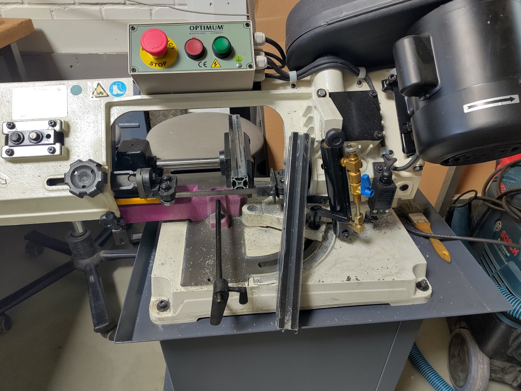
cutting the aluminium profiles
2 / 6
installation of anti-vibration feet
3 / 6
4 / 6
screwing in the automatic connectors
5 / 6
the problem of deformation
After assembling the underside with the automatic connectors, Kerstin and I assembled the top of our machine using the angle pieces designed by Julian and attached the back and side panels that Kerstin had lasered. Once we had that in place, I turned my attention to the back and the electrical system.
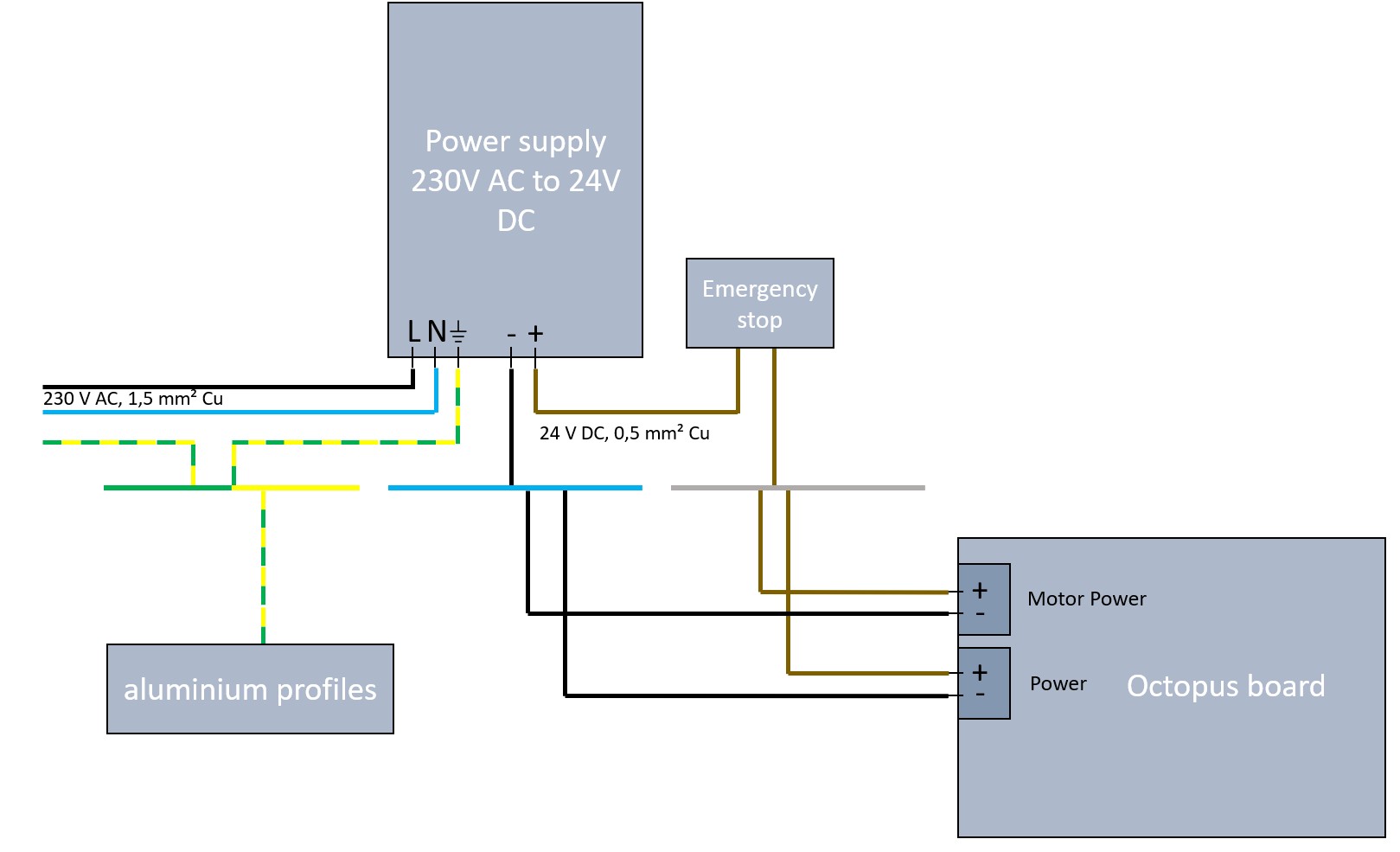
Electricity, electrical safety
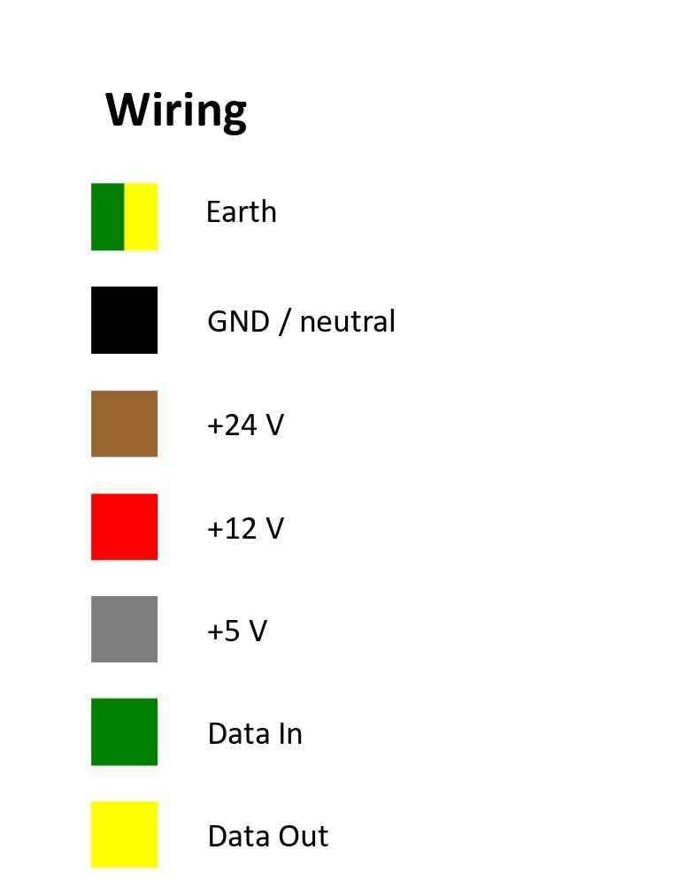
In advance of this week, I thought about the electronics and pushed hard for us to use a DIN rail and put all of our electronics on it. In addition to an adapter for our mainboard, which we downloaded from Thingiverse, we mainly worked with terminal blocks. All the cables we had ourselves follow a color scheme, allowing us to debug hardware-wise in the event of a fault. I set this up based on the cables we had available in different cross-sections. For cable connections that don't lead to a circuit board, we use classic wire end ferrules in accordance with German norms and standards. All metal parts of our setup are protected against the hazard of indirect contact with an earth connection. Of course, we have also implemented the most important feature of every machine, the emergency stop switch, even if it switches the loads directly, which it should not normally do..1 / 5
2 / 5
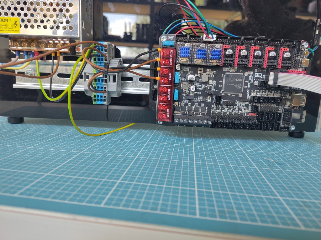
mounted DIN rail with assembled components
3 / 5
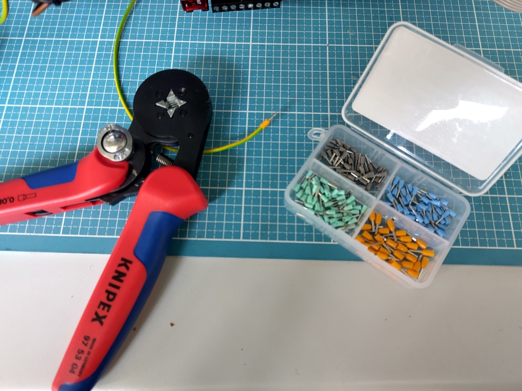
wire end ferrules
4 / 5
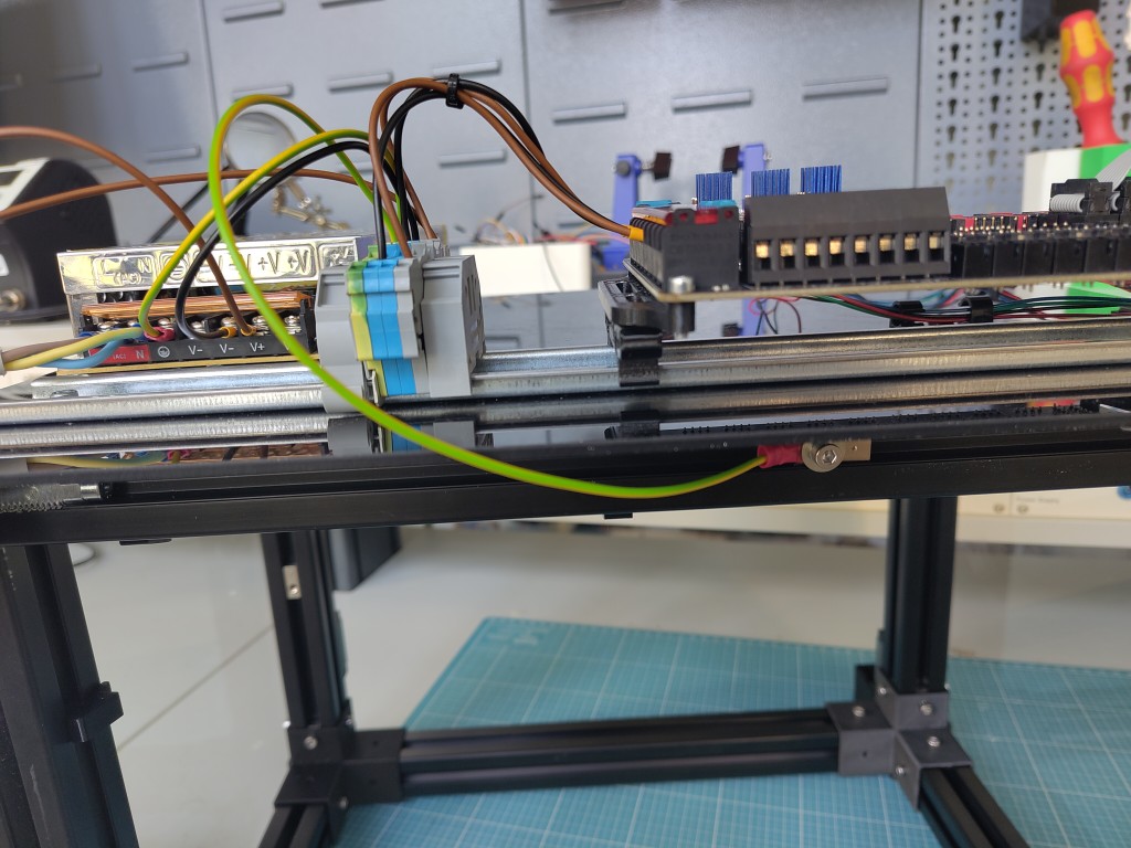
connection to earth
5 / 5
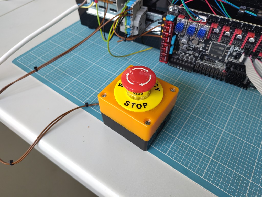
emergency stop
Assembly of our mechanical components
Unfortunately, I was so sloppy with the assembly that I didn't take any pictures. Basically, I just took the 3D-printed parts from Julian and the linear guides that Kerstin had cut to length with a grinder, mounted the carriages, attached the motors to the sides and the device for tensioning the belt over the pulley, and assembled the whole thing, including the belt. I also sawed the aluminum profile for the X-axis to length, grindered the corresponding linear guide myself, and screwed everything on, as well as mounted the head I designed with our Z-axes onto the X-axis carriage. The only thing missing was attaching the mount for the belt that moves our X-axis – Julian took care of that shortly afterwards. Nevertheless, the work ended with the result that we had completed our mechanical design at this point, and our esteemed colleague Markus was able to record the following video:Construction of our head (Z-axis)
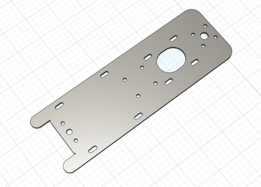
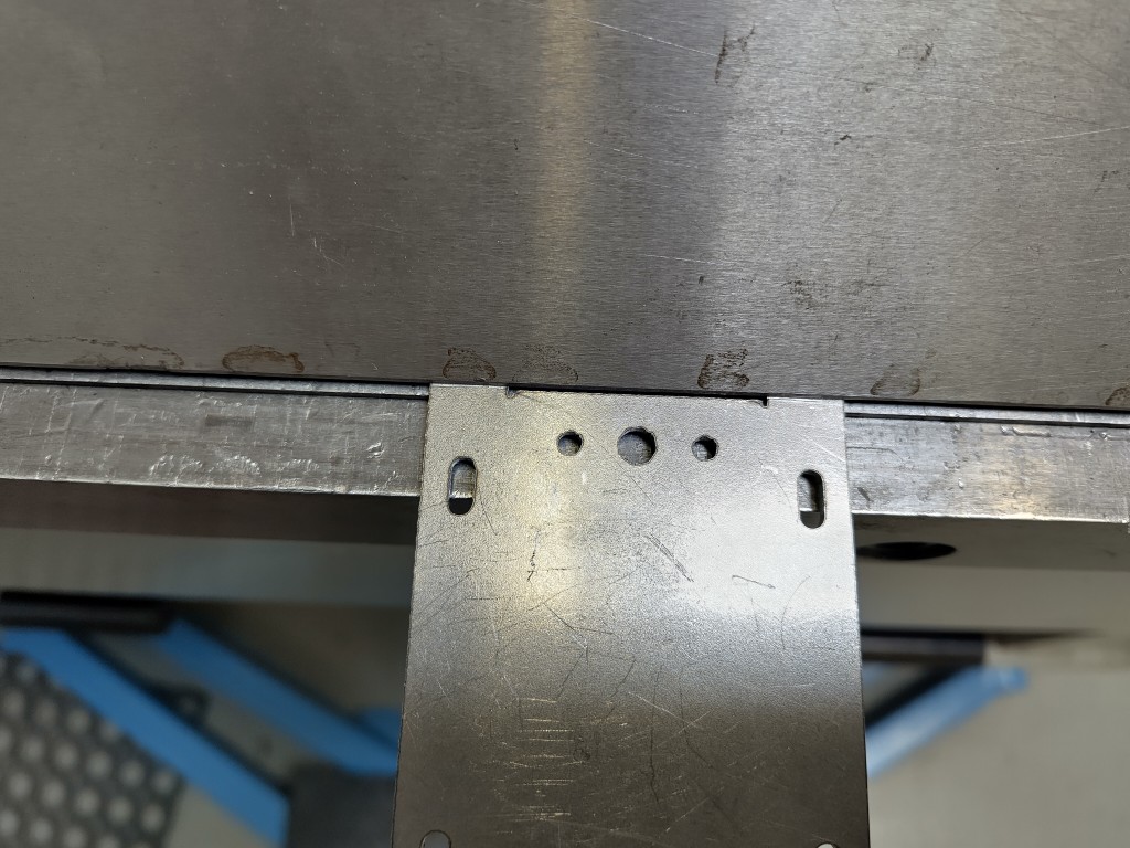
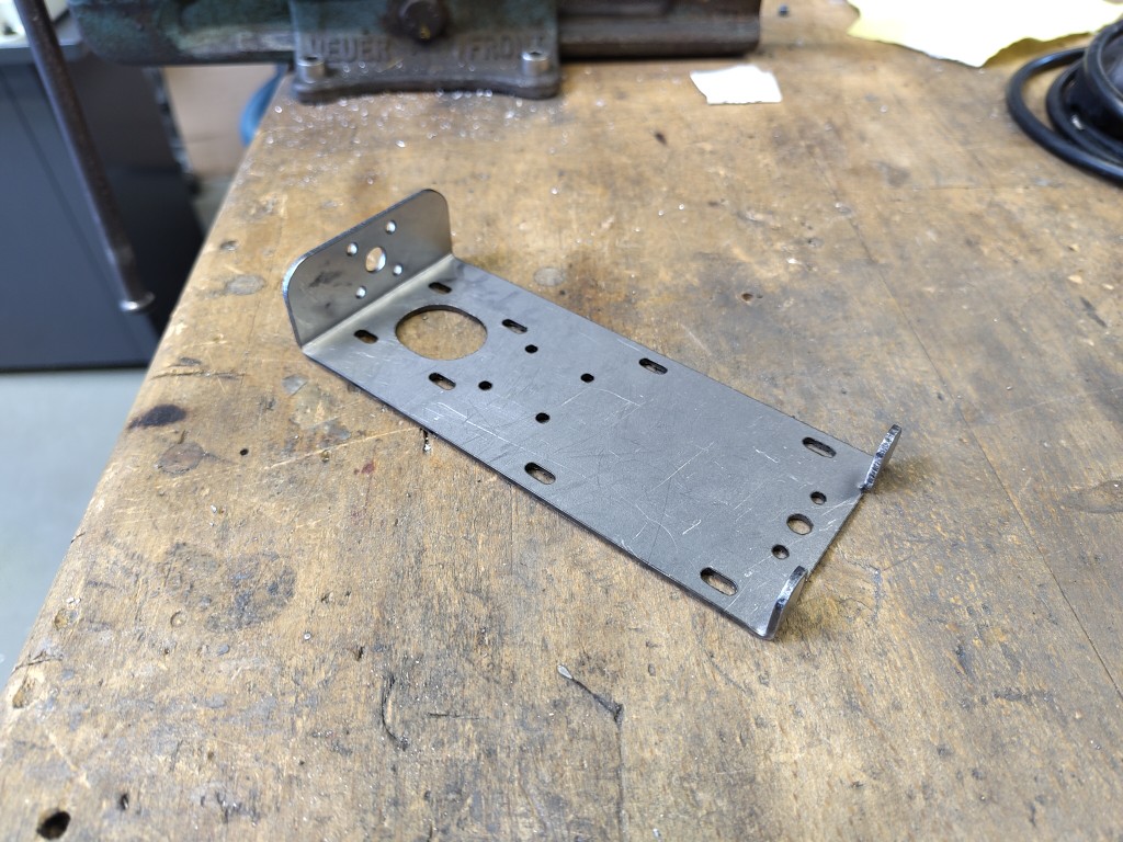
We had planned in advance to be able to move two heads along the Z-axis, similar to the pick-and-place machine that inspired us. At the same time, the design isn't particularly complex; our complexity lies primarily in the build space. However, we didn't give the Z-axis design much thought, which we regretted relatively early on in the Mechanic Design week. With the materials we had at hand, we would have always encountered problems in one place or another because we wouldn't have been able to drill holes the way we needed to without the high probability of breaking several drill bits. After some deliberation and various conceived and partially designed Z-axis designs, we decided to build our head, which forms the Z-axis, according to our first envisioned version – because, mentally speaking, we were already somewhat weakened. We were able to achieve this by using a 2 mm thick steel plate as a base and laser-cutting all the holes, recesses, and bending axes we needed. I took on this task, so all the blame for anything that doesn't work goes to me. Here is the design of the plate as I lasered it in 2D. We fold the upper part over 90 degrees so that we have another base there to thread the cable and our hose through the center of the hole in the head, while also relieving some of the tension with a potential 3D-printed component. Below this, the motor for our Z-axis is inserted from behind through the steel part and mounted in a slightly movable manner, because we want to use this attachment to tension the belt later. The four holes below this are for attaching the X-axis carriage, on which our head moves. There are elongated holes on each edge for flush mounting two linear guides and also for flexibility, because we can probably only work with millimeter precision when sawing. On the underside are tabs that we bend upwards to stop our carriages on the Z-axis and prevent them from falling out. The bottom center holes serve to suspend the pulley, allowing us to attach our GT2 belt centrally between it and the motor. I laser-cut the plate, then deburred and beveled it.1 / 9
CAD Design
2 / 9
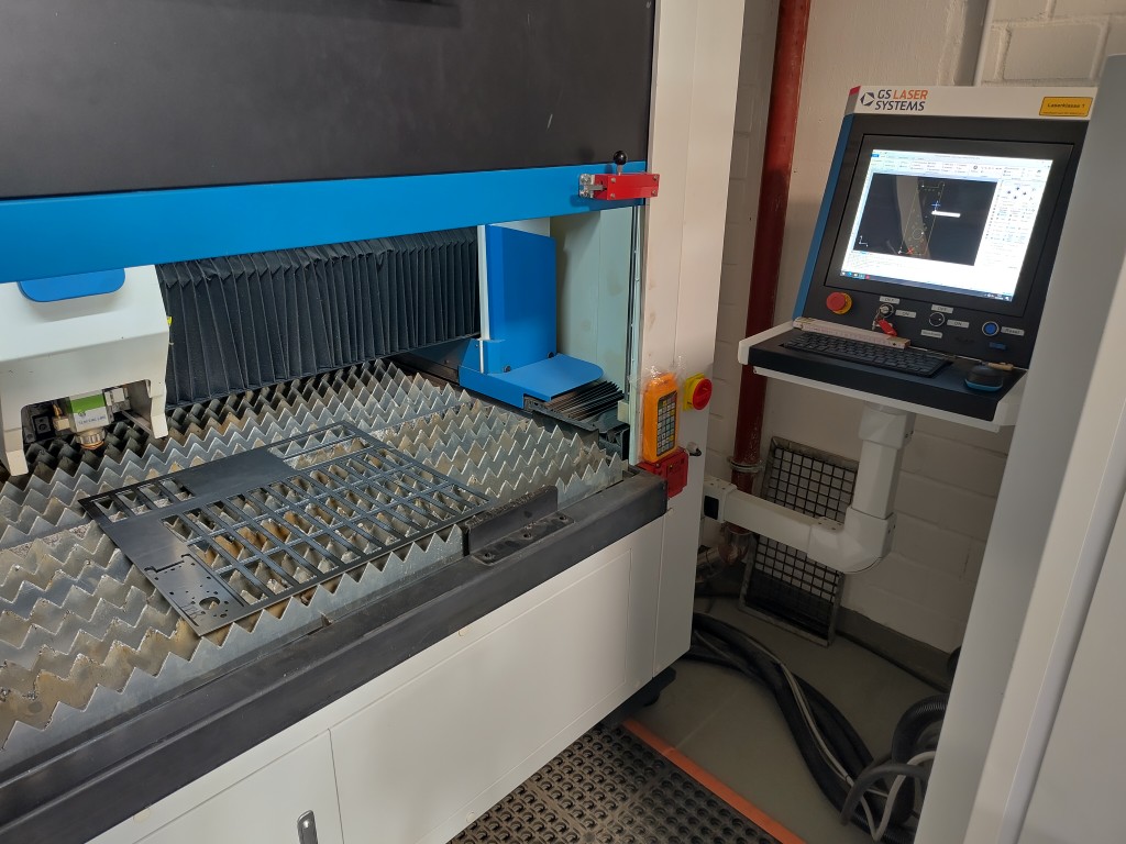
lasercutting
3 / 9
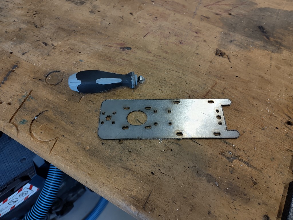
deburring
4 / 9
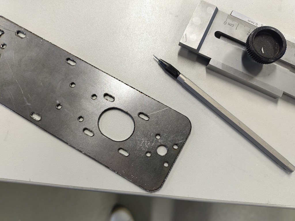
marking for bending
5 / 9
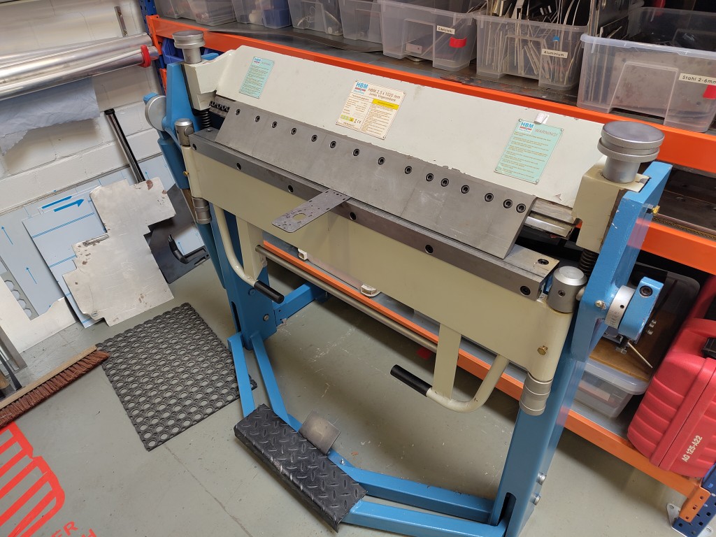
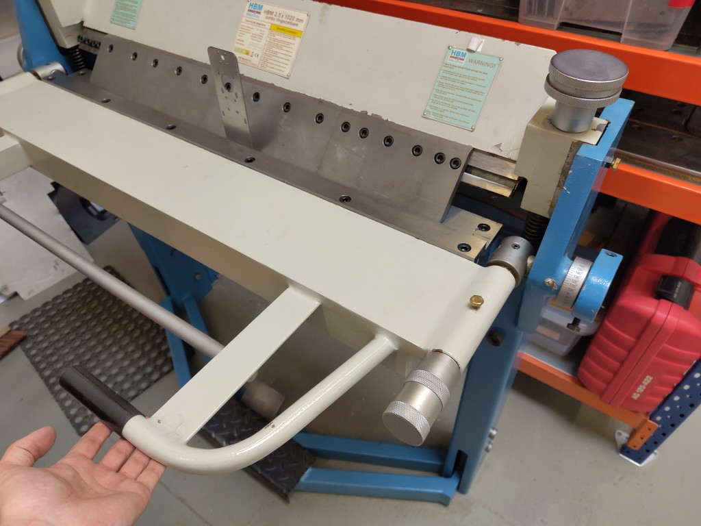
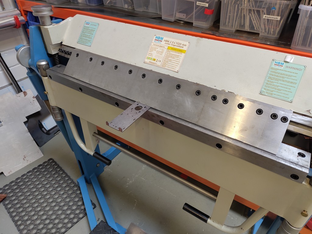
bending
6 / 9
7 / 9
8 / 9
9 / 9
the curved result
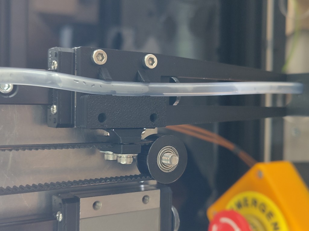
The next step, of course, was to finalize the head. To do this, I screwed on the motor, attached the pulley at the bottom, and cut the linear guides to length. Thankfully, Kerstin cut these to size with a grinder and supplied them to me, so I could then mount them on our head with a carriage. This short video shows the bare mechanics, which I briefly tested for functionality. The belt also worked well, even though we already knew at this point that we would have to replace the clamp again. Unfortunately, as with many things that day, I forgot to take pictures or videos.
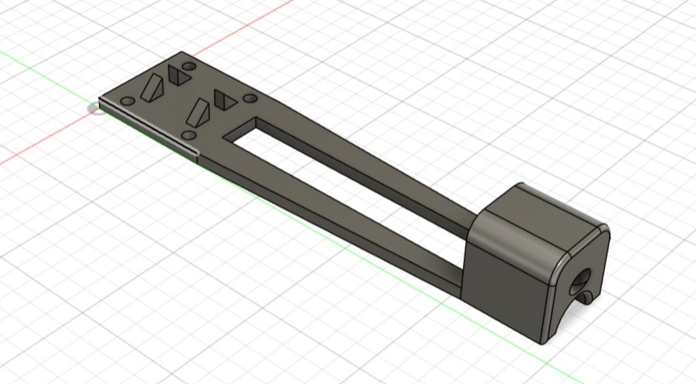
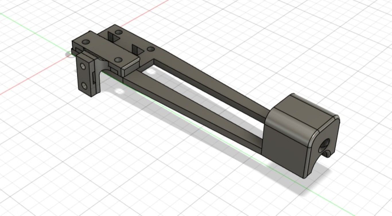
On the right in this video is the top of our head. We want to route our hose and any cables through the large hole on the 90-degree bent side in the center. The four surrounding holes give us the opportunity to create and secure 3D-printed structures that close off the head and simultaneously provide strain relief for the components mentioned above. Directly below are elongated holes for securing the motor for our Z-axis, including the corresponding round cutout in the center. Also below the motor are four small screw holes for attaching the carriage that slides on our X-axis. Originally, this attachment, the existing levers, and the rigidity of the metal were the deciding factors for manufacturing the head using this manufacturing method.
On the right in this video is the top of our head. We want to route our hose and any cables through the large hole on the 90-degree bent side in the center. The four surrounding holes give us the opportunity to create and secure 3D-printed structures that close off the head and simultaneously provide strain relief for the components mentioned above. Directly below are oblong holes for securing the motor for our Z-axis, including the corresponding round cutout in the center. Below the motor are four small screw holes for attaching the carriage that slides on our X-axis. Originally, this attachment, the existing levers, and the rigidity of the metal were the deciding factors for manufacturing the head using this method. Below the attachment on the X-axis, there are also oblong holes on the edges for attaching two linear guides. As mentioned, we will be working with two heads due to their different functionalities. We will attach both to the belt in such a way that one is in its upper and one in its lower position at all times. The linear guides fit flush. Bending up the tab on the bottom side serves to stop or secure the carriage. The center hole accommodates an M5 screw, which we can use to attach the pulley. We've provided additional holes to the left and right of it for flexibility.
The head's design is fundamentally based on the idea of locating the motor centrally, while simultaneously having two heads. We discussed distributing both the bulk material and the liquid on a single head and thus using a single linear guide, but we didn't arrive at a more effective solution any faster. This would have required positioning the motor and pulley to the side of the rail, saving only a small amount of space. At the same time, we would have introduced a weight imbalance whose potential impact we weren't aware of. Aluminum profiles weren't suitable, and we didn't trust plastic for this location, so the mechanism above resulted.
A quick update: When designing the second head, which we plan to use to spread seeds or other solids like sugar or effervescent powder, we realized that the upper bend severely restricted our space. At the same time, initial tests showed that the hose we wanted to run there would cause excessive friction. Therefore, we decided to adapt the design. Kerstin took care of this, and I only reassembled the old head. Particular care must be taken here, because the linear guide carriage will only stop when the heads are fully connected; if the assembly is incomplete, it could fall out.
3D parts
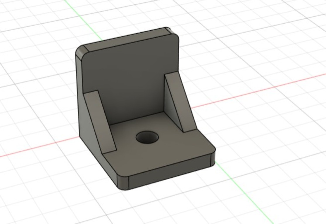
3D design was rarely my domain; Julian and Kerstin did the majority of the work there. I only contributed a few quick parts. One example was the adapter for screwing our anti-vibration feet into the bottom of our extrusion with an M3 screw. We also realized on the fly that we needed a mounting option for the peristaltic pump, which ideally should be located on the back of the device. With a few quick measurements of the pump and a few clicks, i created the following model, which we then printed and installed. Similarly, we spontaneously realized that we needed to secure our carriage on the X-axis even better than the offset caused by the 3D-printed angle. Therefore, I designed a simple stop and installed it on both sides.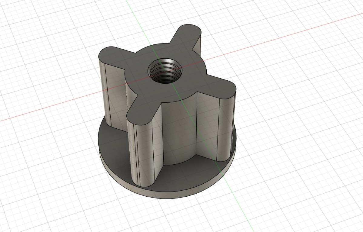
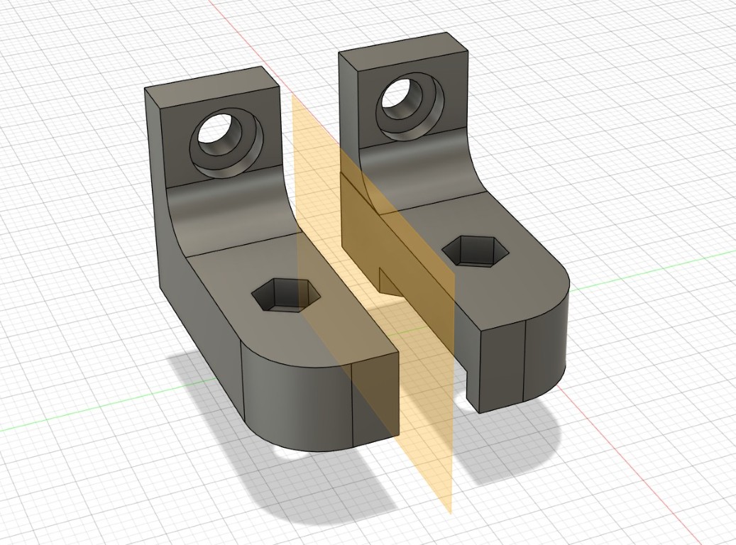
Head 1 - Fluid distribution
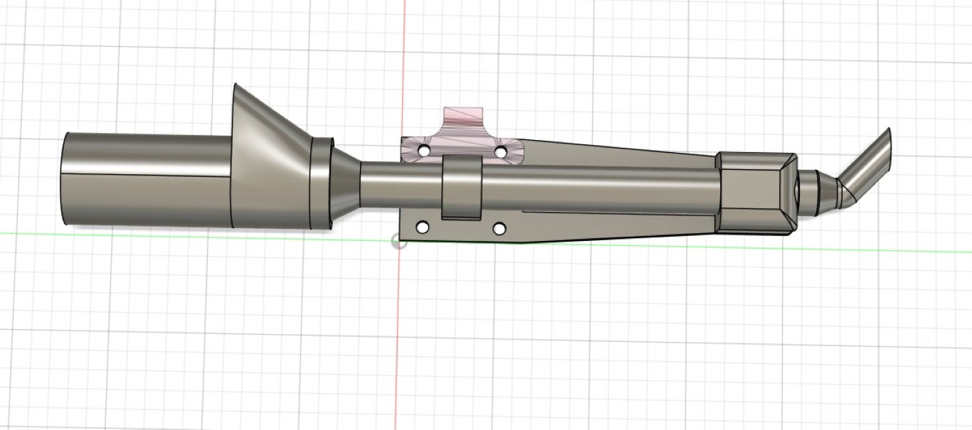
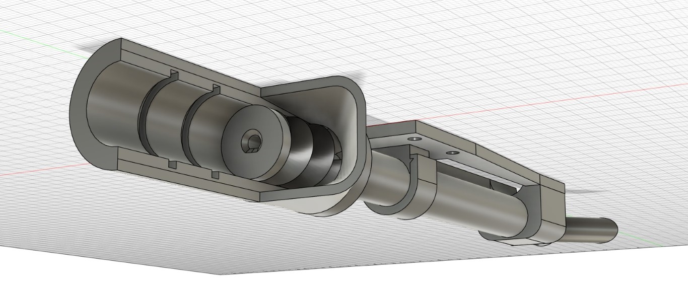
The design for the head, in which we attach the hose from our peristaltic pump so that we can irrigate from it, is a bit more complicated. The stop for the carriage on the Z-axis creates a cutout in the middle and a curve at the very bottom to avoid collisions. To maximize the travel, the mount for the belt, which also connects it, is located centrally between the bores of the carriage. The extremely elongated head is due to the fact that we need to be able to move relatively close to our pints so as not to spill too much of our precious liquids. The feedthrough for the hose is angled inside the lower block so that it ejects the liquid in an arc, so that it arrives 2.5 cm from the borehole and centrally below our entire head. This way we don't lose any additional installation space because we have to move the entire head sideways to irrigate, sow, or otherwise fill the same spot.1 / 3
just the head
2 / 3
fully equipped with all attachments
3 / 3
printed and assembled - with two screws still missing
Here the head is in action, even if it is still dry.
Head 2 - Solid ejection
Over the last week, the loss of a team member within the project has given us an even higher workload, as we had to pull Julian away from the second head and relocate him to implement the programming. He nevertheless developed a cool design, with a completely different approach than mine, that is definitely worth checking out – at the same time, we agreed to make the second head's functionality my responsibility.Given the short time frame and the spontaneity, I only briefly looked at common solutions, which often involve screw conveyors. I adapted the design to a large extent from my first head, including for launching from the same height. The downward movement of the head, closely past the belt, creates difficult requirements in terms of the installation space for the head. Because it's a quick and dirty design, I assembled it from many interchangeable parts, with short iterations and revisions. That's how it stayed in the end.
After a long search in the lab, I came across a small gear motor that seemed promising for its slow rotation speed. At the same time, it's wonderfully small, meeting all our requirements. Therefore, I designed all the parts surrounding the screw conveyor around this motor.
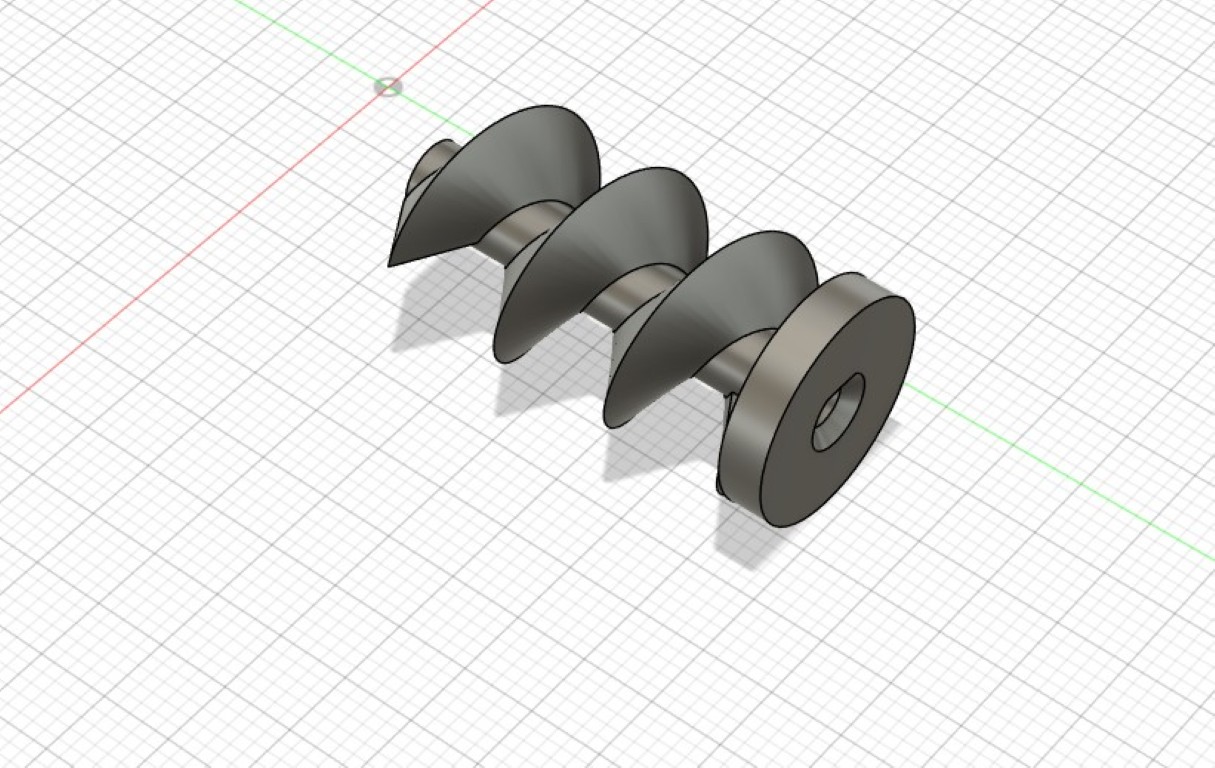
When working with screw conveyors, the general question seems to be how to arrange them. Roughly speaking, you can distinguish between vertical and horizontal arrangements. As you can see, I mounted the screw conveyor vertically. This brings with it the problem that, in practice, bulk material always trickles out the bottom due to gravity, especially when the entire structure is in motion. This problem wouldn't arise if the material were fed horizontally via a screw conveyor into a similar downpipe, because no material would slip down. Unfortunately, we don't have the space for this setup. With a vertical screw, you could also prevent this problem by, for example, attaching a flap that only opens during conveying. In the spirit of spiral design, this would be a great extension if you could invest more time in it. Smaller effects can also be achieved by playing with the screw conveyor itself.
If we stick with Fusion360, we specify both the length and the number of turns when creating the screw. This primarily changes the thread pitch. With a higher thread pitch, gravity is obviously stronger, which is why particles trickle out more quickly than if we were working with many turns and therefore a lower thread pitch. Here we have the problem somewhat under control, but you can still see the trickling out in the following video. Due to the design, you'll never be able to get it 100% under control without a flap. If you're toying with the idea of building a replica or want to adapt the principle for yourself, I can only recommend testing this parameter very individually (also depending on the material to be conveyed). If space allows, I would definitely switch to a horizontal screw conveyor.