Networking and Communication
This weeks individual assignment:
- design, build, and connect wired or wireless node(s) with network or bus addresses and local input &/or output device(s)
This weeks learnings:
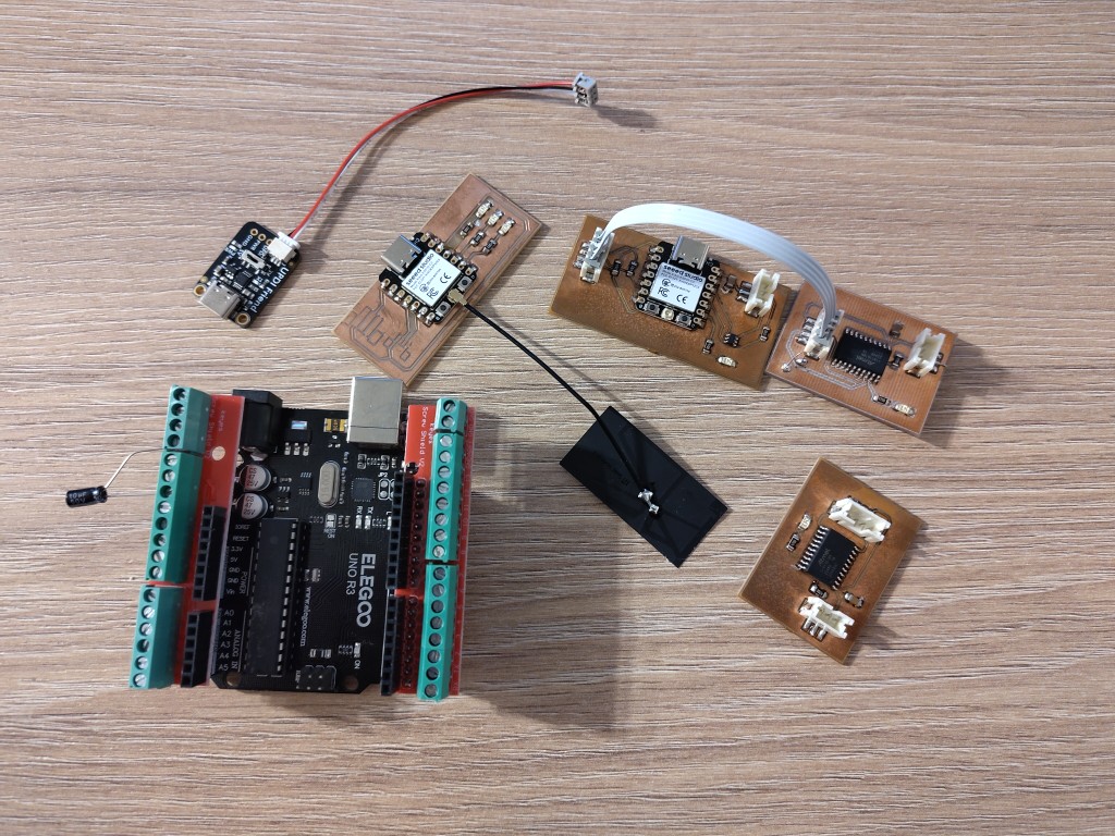
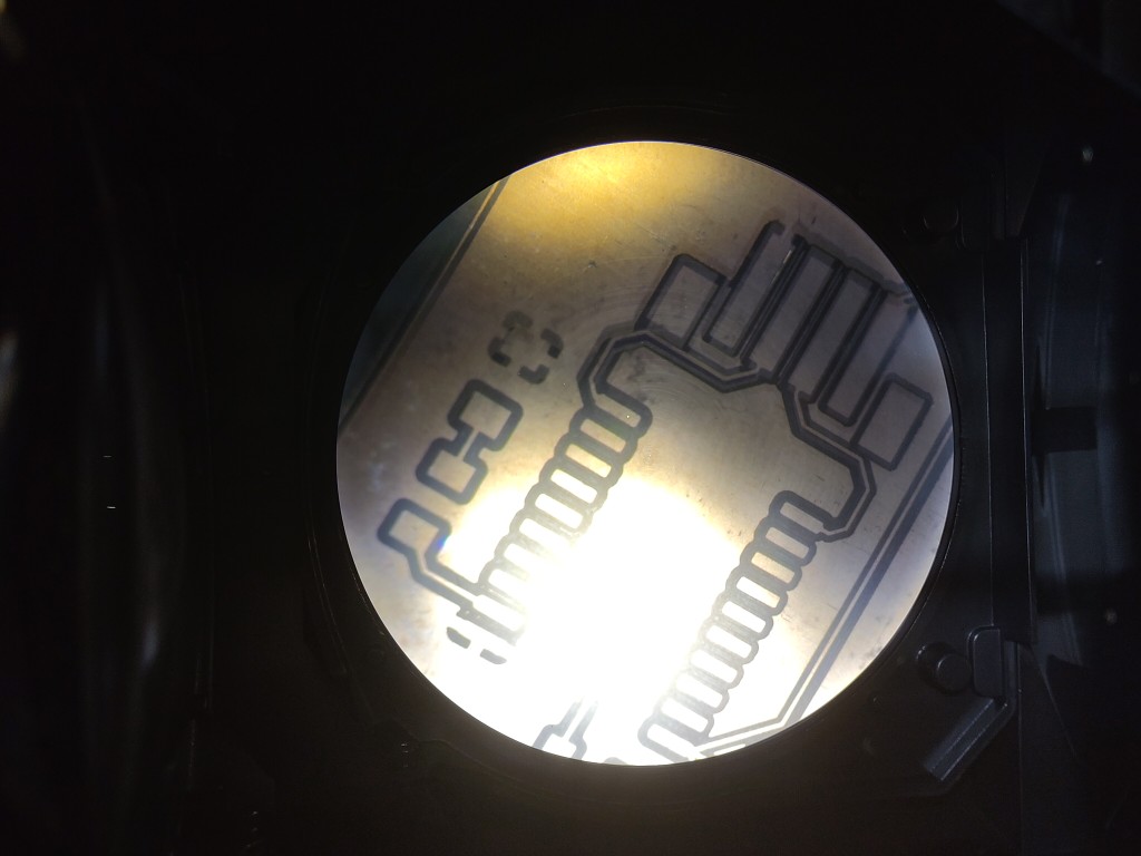
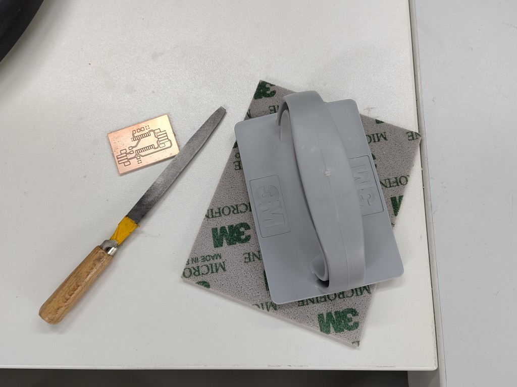
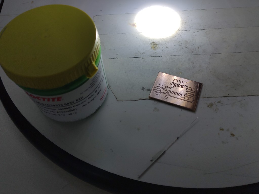
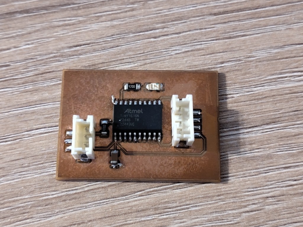
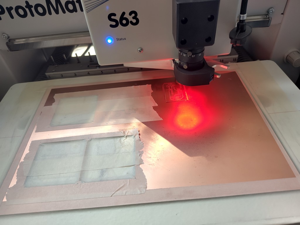
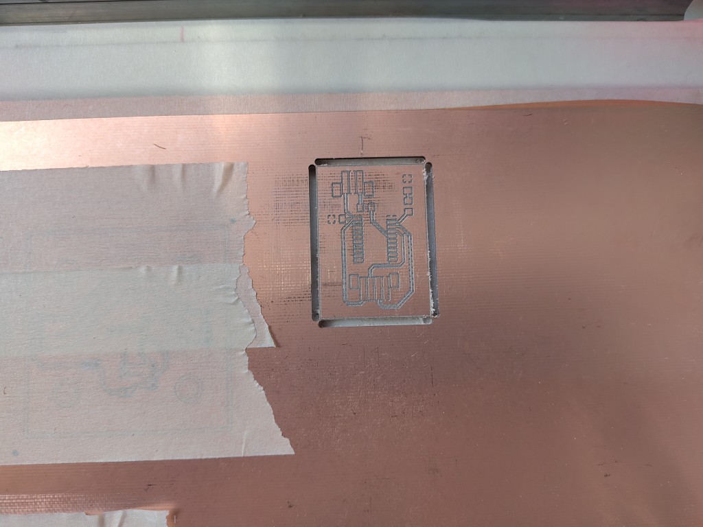
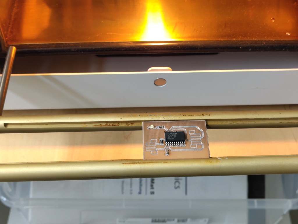
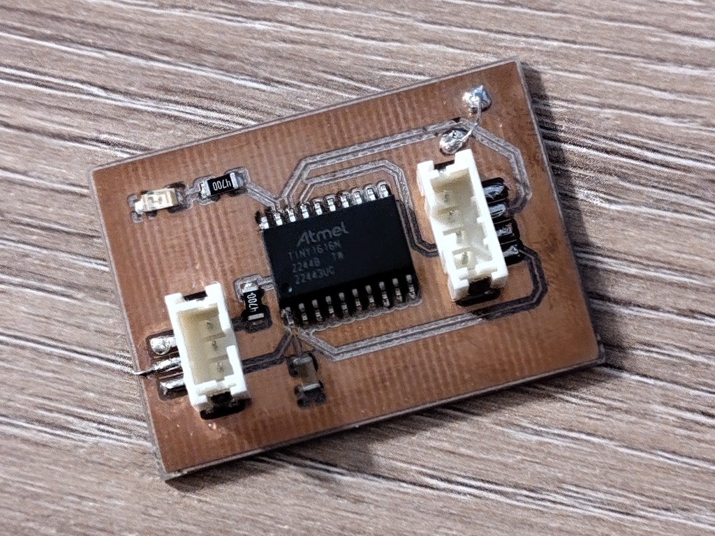
You may have noticed last week that I wanted to work with the ATTiny1616. My overall plan is to link it with the ESP32C3 to realize my project. So this week I'll be working on integrating the two microcontrollers. The ESP32 makes programming very easy, but things are a bit different with the ATTiny. Last week, I failed to flash it because I made mistakes on the board.So I designed and milled a new board for this week, which I'm pleased to present in the following slideshow.
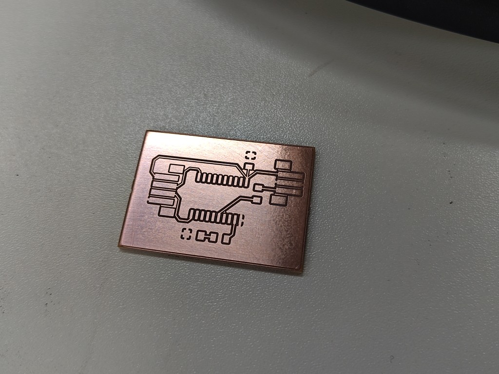
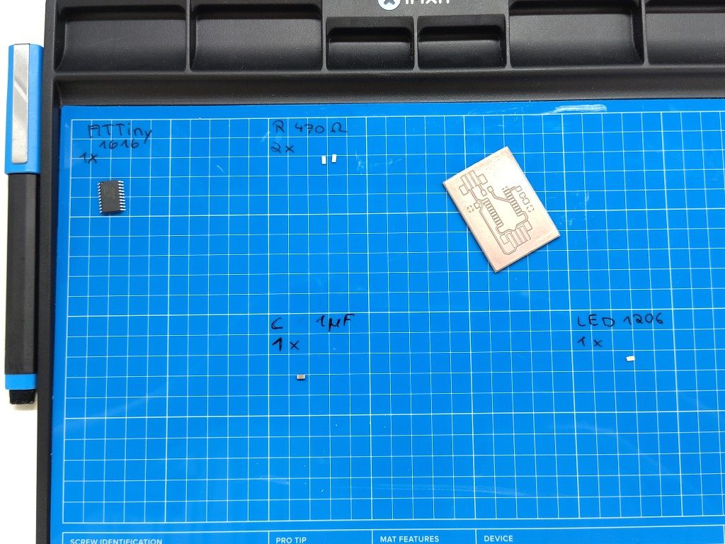
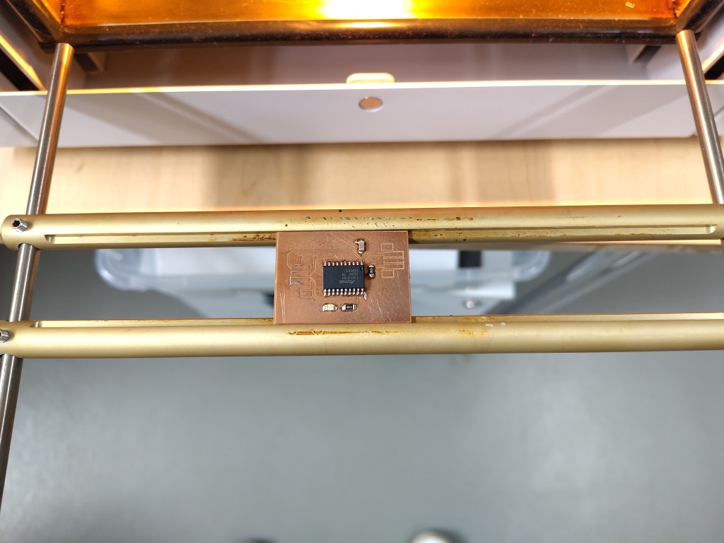
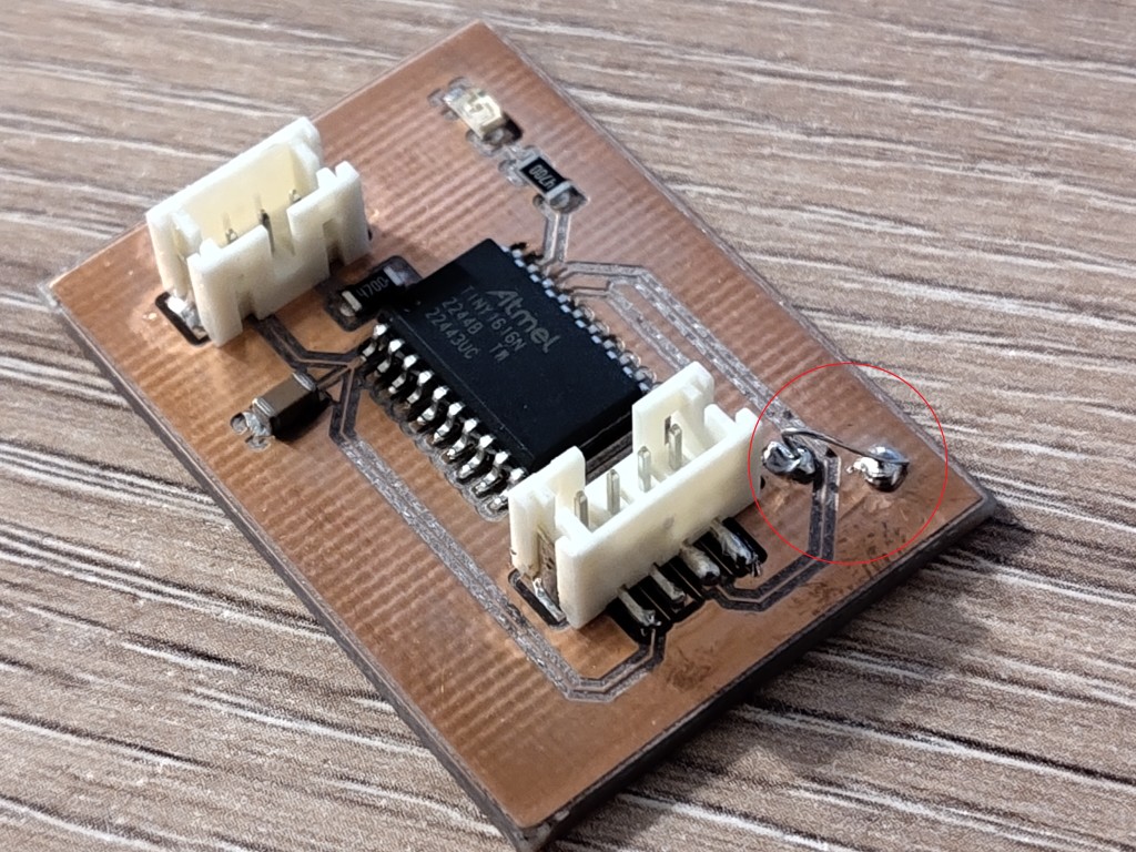
As you can see, I've installed an LED this time for debugging. The reason I had to connect the WS2812b LEDs during my last attempt without knowing if the flashing would work was to see if it might have actually worked. The whole thing would involve fewer points of error and variables if a simple LED was directly on the board, so from now on, this will be the case on every one of my boards—including a series resistor, of course.
This is what my finished board looks like. Personally, I think it's an exciting board because it combines looking good from far and far from good in an incomparable way.
UPDI programming
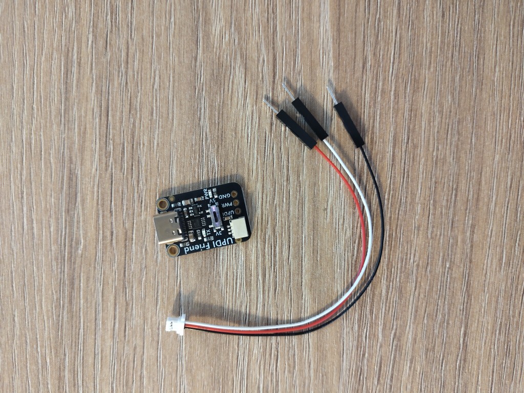
Knowing that I'd have to program the ATTiny differently, I got myself an Ardafruit UPDi Friend. Long story short: We spent quite some time together, but we didn't become friends. I'm very strict with technical friends; the friendship has to be mutually beneficial. Unfortunately, that wasn't the case here, despite my many attempts to approach him and reading and following instructions on how best to do this.For the record: This is what my distant acquaintance looks like.
The instructions enabled me to flash the following code onto my ATTiny:
void setup() {
  pinMode(PIN_PA3, OUTPUT);
}

void loop() {
  digitalWrite(PIN_PA3, HIGH);
  delay(500);
  digitalWrite(PIN_PA3, LOW);
  delay(500);
}
What probably sounds boring to you was almost like a celebration for me at this point.
I2C Communication
Out of a certain frustration that the week hasn't ended for me yet, I contacted ChatGPT and described my situation so it could generate a simple demo code for me. Here is the conversation:Me: I want to communicate via I2C between an ESP32C3 (from Seed Studio) as the teacher and an ATTiny1616 as the student. Can you generate the simplest possible demo sketch for both controllers? I'm working with the Arduino software, so I'd prefer to use C.
ChatGPT:
Sure! Here's a minimal example code for I2C communication between:
an ESP32-C3 (e.g., XIAO) as Teacher
an ATtiny1616 as student
You're using the Arduino IDE, so the example is written entirely in C++/Arduino-compatible code and includes the usual libraries (Wire.h).
🔧 Preparation
🧩 Wiring
| Signal | ESP32-C3 (XIAO) | ATtiny1616 |
|---|---|---|
| SDA | GPIO8 | PA2 (e.g.,) |
| SCL | GPIO9 | PA3 (e.g.,) |
| GND | GND | GND |
| VCC | 3.3 V or 5 V* | VCC |
💡 Make sure the voltage levels are the same or use level shifters.
⚠️ ATtiny1616 Setup in Arduino IDE
Install megaTinyCore
Select Board: "ATtiny1616"
Set I2C pins using Wire.setPins(SDA, SCL) if necessary
📟 ESP32-C3 Code (Teacher)
#include <Wire.h>

#define I2C_SLAVE_ADDRESS 0x12

void setup() {
  Wire.begin(8, 9); // SDA = GPIO8, SCL = GPIO9 auf XIAO ESP32-C3
  Serial.begin(115200);
  delay(1000);
  Serial.println("ESP32-C3 Teacher gestartet");
}

void loop() {
  Wire.beginTransmission(I2C_SLAVE_ADDRESS);
  Wire.write("Hello");
  Wire.endTransmission();

  Serial.println("Nachricht gesendet: Hello");
  delay(1000);
}
#include <Wire.h>

#define I2C_ADDRESS 0x12
#define LED_PIN PIN_PA3 // z. B. für Reaktion per LED

void setup() {
  pinMode(LED_PIN, OUTPUT);
  digitalWrite(LED_PIN, LOW);

  // Falls du nicht die Standardpins PA2/PA3 verwendest:
  Wire.setPins(PIN_PA2, PIN_PA3); // SDA, SCL

  Wire.begin(I2C_ADDRESS);
  Wire.onReceive(receiveEvent);
}

void loop() {
  // nichts notwendig im Loop
}
Same I2C address (0x12) on both
I2C lines with pull-up resistors (4.7kΩ recommended)
Use Serial.println() on the ESP for debug output
If ATtiny doesn't respond: Check Wire.setPins(...) and the correct TWI Sercom assignment according to the megaTinyCore documentation
If you want a return channel (ESP asks ATtiny for data), I can add that too. Just let me know!
That's it, ChatGPT has written another novel. If you've read this far: I've set up two Arduino projects using the code ChatGPT generated.
If we look at the code for the ATTiny, we notice that pin PA3 would be used for both I2C and an LED. This is nonsense, of course, regardless of the fact that ChatGPT couldn't know from my input which pins would be used and how. I adjusted the pins and compiled the code.
The short pause was just to build suspense. Nobody needs that; of course, ChatGPT's code didn't work. Neither did any other code I could find online or piece together myself. I chose pins PB1 and PB0 for I2C communication on the ATTiny because they fit my board design better. On the ATTiny, this would correspond to TWI1; typically, pins PA1 and PA2 are used, although the datasheet also lists the pins I used. With this knowledge, and especially because I had no way of getting any kind of feedback on which pins actually were being used for the I2C communication attempt, after long and frustrated attempts, I decided to change the pins and otherwise rebuild the board unchanged.
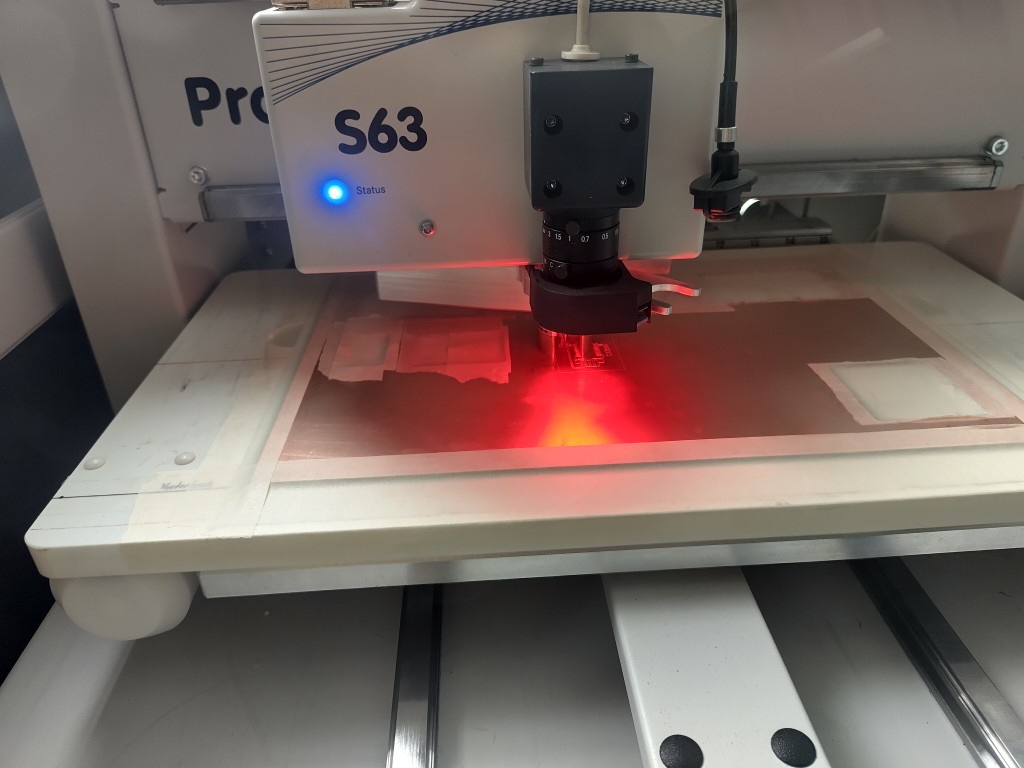
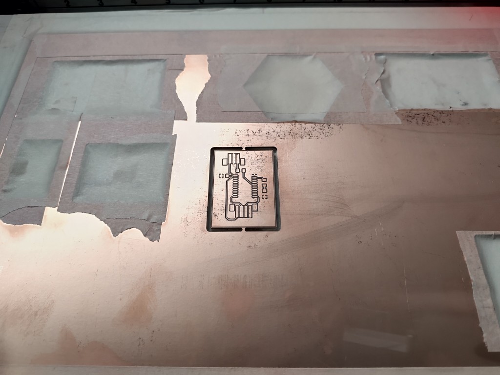
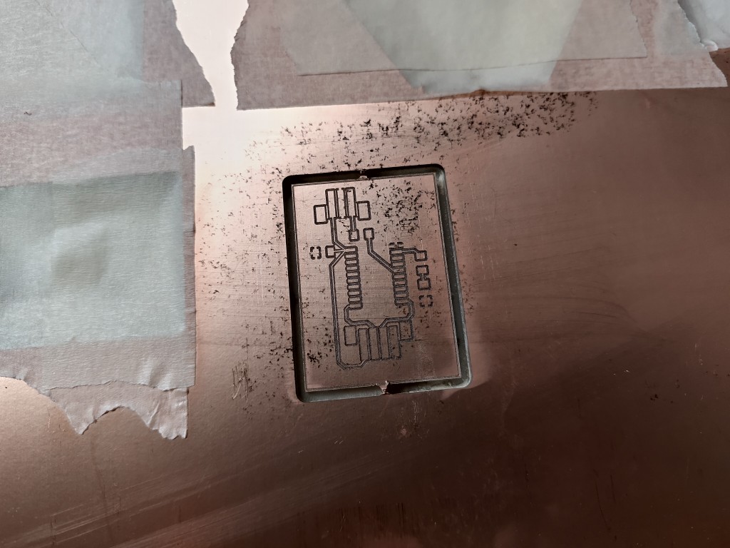
With renewed hope deep in my heart, I set about milling and assembling the new board the next day. My hope was further fueled by the fact that the process ran smoothly as usual. What a pleasant surprise!
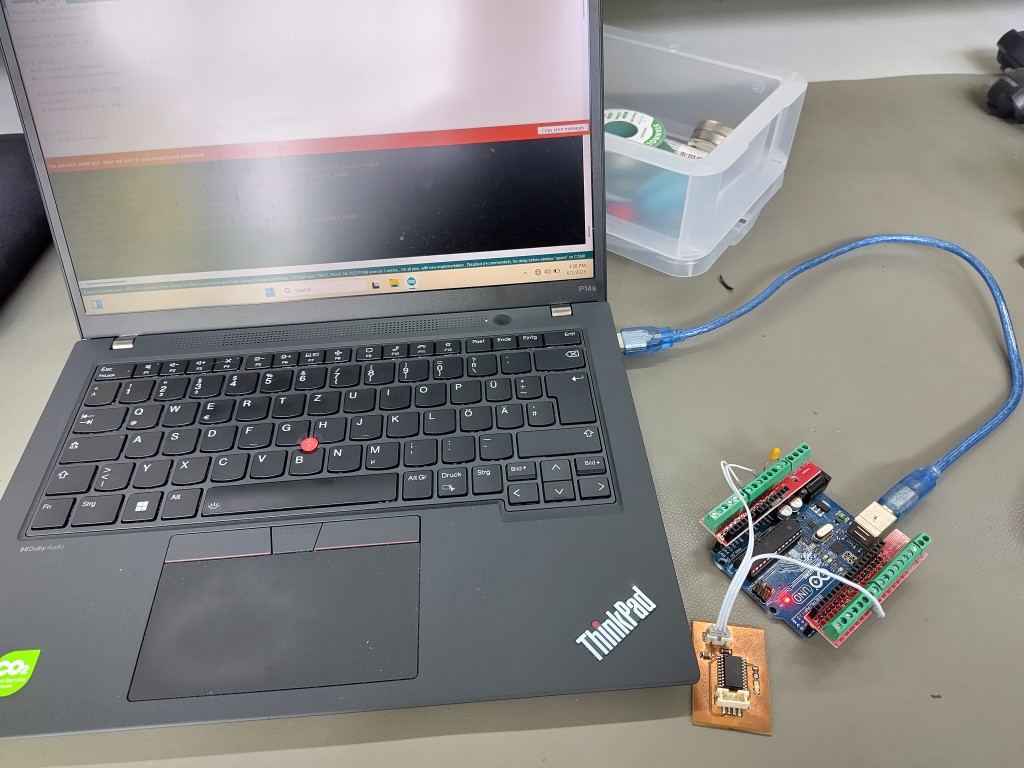
That was it, and I was ready to connect my new board. I used the same setup and programmer that had worked so well at home the night before. Thanks to my screw terminals, I didn't even wiggle the cables. As you might expect from reading this, the change in the air towards the lab didn't do anything good that day.
In short, flashing test code resulted in this:
From that point on, his presence unfortunately no longer had the desired effect, and I got the same old error messages. With both the new and the old board. And also with Julian's Arduino Uno, which he had been using for flashing without any problems up to that point. At this point, we were in hour 8 of the day, and I just wanted to quickly check whether the pin assignment on the ATTiny was the problem. Because I was running out of courage and advice, even though the absurdity was certainly entertaining, I decided to seek a change of scenery. My boards and programmer were also gone. Out of sheer fun and desperation, I tried flashing code onto my boards again, unchanged. And I succeeded!
As if nothing had ever happened, 10 out of 10 attempts worked immediately with both boards. I've rarely laughed so much while crying. Just to keep up with the odds, two more flashes failed due to the error, which, by the way, was a complete lie from the start (the voltage was measurably high). About ten flashes worked again, unchanged. Why did I flash so often? Because I had hopes of getting my I2C communication working with code changes. Why didn't I flash more? Because I no longer had hope of getting my I2C communication working with code changes.
In total, I tested various libraries, including the TinyWire libraries. I ran a simple I2C scanner on the ESP32C3 and couldn't find a board. I tested roughly the code you can find online. I tried changing the air flow, turning the laptop on and off, measuring my circuits multiple times, including all the cables, checking all the components, and, of course, asking everyone I could about this topic.
Lesson learned: If your ATTiny is having problems flashing, try changing the air flow, ideally combined with the vibrations of a 37 km car ride, about 30 km of which are on the highway. That worked for me. I2C is definitely cool, but here, too, I left a friendship behind.
ESP-Now
There was too much inexplicable coincidence involved for me to waste any more time on this. So I found new friends, and since this week's requirement was to work with boards I'd made myself, I dedicated myself to ESP-Now and combined two boards.Because the cooperation with Chat-GPT on I2C was so fruitful, I decided to map ESP-Now with every other knowledge source imaginable. In my case, the vastness of the internet, specifically YouTube, led me to this tutorial, which I highly recommend. However, it's only for German-speaking users, even though it's based on the English-language tutorial from Arduino itself.
ESP-Now itself, as the name suggests, is a protocol that enables communication between ESP microcontrollers. It works wirelessly and can connect up to 20 microcontrollers, each of which can act as a transmitter, receiver, or transceiver. MAC addresses are used to address the messages, which brings us directly to the first important step.
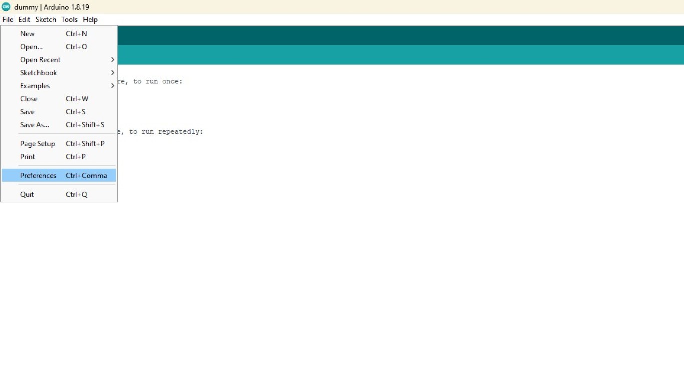
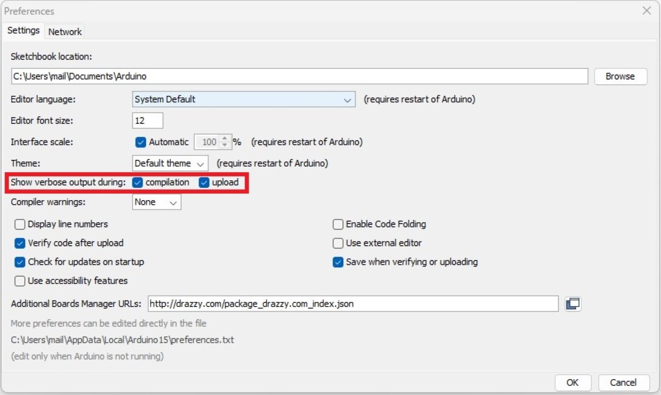
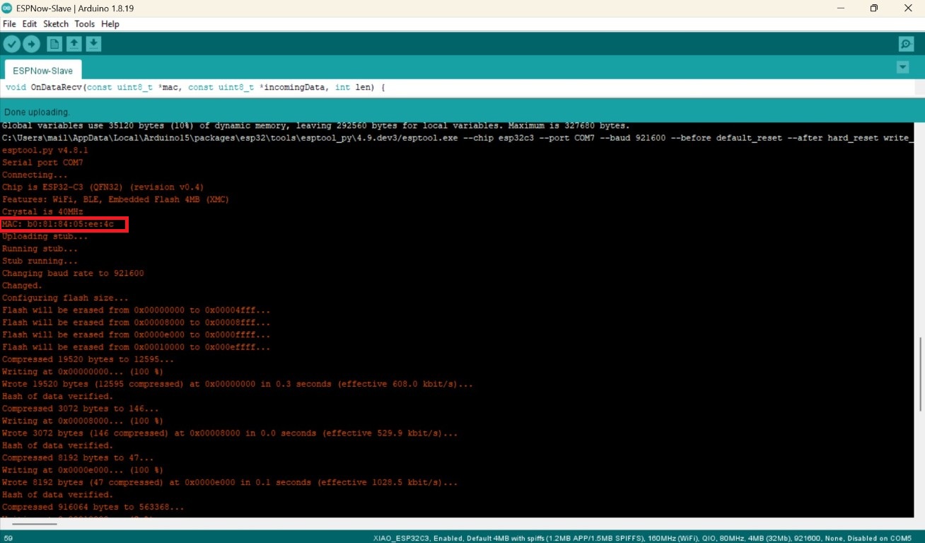
Because I've often been told that untreated PCBs don't last long in the air, I initially loaded the old code from week 8 onto my board to see if it still worked. Fortunately, it did. To be able to troubleshoot problems as best as possible, I used the Arduino software settings to output all logs during compilation and flashing while working with UPDI. The logs are hidden behind the orange output, which you may have seen in the error message above. Here's a slideshow on how you can enable them:
If you scroll up in the logs, you'll also find the MAC address, as in my case here.
On the receiver, this "only" causes the middle LED to toggle; after my wonderful experiences with the ATTiny, I used the two outer LEDs to actually show that the code is working and running.
You can find my code directly here or download it below.
Teacher
#include
#include

int led1 =8;

// MAC-Adresse des Zielgeräts (Empfänger)
uint8_t broadcastAddress[] = { 0xb0, 0x81, 0x84, 0x05, 0xee, 0x4c };

// setting the structure for data transfer
struct Message {
  bool isActive; // saving the leds status
};

// Create an instance of the message structure
Message message;
// Defines information about the ESP-NOW peer (the receiver)
esp_now_peer_info_t peerInfo;
// Callback function that is called when a message has been sent
void OnDataSent(const uint8_t *mac_addr, esp_now_send_status_t status) {
  Serial.print("\r\nStatus:\tZustellung ");
  // Displays the status of the message: successful or failed
  Serial.println(status == ESP_NOW_SEND_SUCCESS ? "erfolgreich!" : "fehlerhaft!");
}
void setup() {
  Serial.begin(115200); // Start serial communication for debugging output

  pinMode(led1, OUTPUT);

  WiFi.mode(WIFI_STA); // Set the WiFi module to station mode (prevents interference)
  // Initialize ESP-NOW and check if the initialization is successful
  if (esp_now_init() != ESP_OK) {
    Serial.println("Error initializing ESP-NOW");
    return;
  }
  // Register the callback function for the shipping status
  esp_now_register_send_cb(OnDataSent);
  // Add the destination address and other settings to the peer info structure
  memcpy(peerInfo.peer_addr, broadcastAddress, 6); // MAC address of the recipient
  peerInfo.channel = 0; // Use the default channel
  peerInfo.encrypt = false; // No encryption
  // Add the peer to the ESP-NOW peer list
  if (esp_now_add_peer(&peerInfo) != ESP_OK) {
    Serial.println("Failed to add peer");
    return;
  }
}
void loop() {
    message.isActive = !message.isActive;

    // Send the message via ESP-NOW
    esp_err_t result = esp_now_send(broadcastAddress, (uint8_t *)&message, sizeof(message));
    // Check if sending was successful
    if (result == ESP_OK) {
      Serial.println("Senden erfolgreich!");
      digitalWrite(led1, HIGH);                          // my modification
    } else {
      Serial.println("Fehler beim absenden der Daten!");
    }
    delay(1000);
    digitalWrite(led1, LOW);
    delay(1000);
}
Student
#include
#include

int led1 =8, led2=9, led3=10;

// Structure for the received data
struct Message {
  bool isActive; // LED status: on (true) or off (false)
};
// Create an instance of the message structure
Message message;
// Callback function that is called when data is received
void OnDataRecv(const uint8_t *mac, const uint8_t *incomingData, int len) {
  // Copy the received data into the local message structure
  memcpy(&message, incomingData, sizeof(message));
  // Output the number of bytes received
  Serial.print("Bytes received: ");
  Serial.println(len);
  // Output the received LED status
  Serial.print("isActive: ");
  Serial.println(message.isActive);
  // Logic to switch the LED:
  // If `isActive` is false, the LED is turned on (inverts the signal)
  bool isLEDActive = message.isActive == 0 ? true : false;
  // Set the LED status based on the received data
  digitalWrite(led2, isLEDActive);
}
void setup() {
  Serial.begin(115200); // Start serial communication for debugging

  pinMode(led1, OUTPUT);
  pinMode(led2, OUTPUT);
  pinMode(led3, OUTPUT);

  digitalWrite(led1, HIGH);
  digitalWrite(led3, HIGH);

  WiFi.mode(WIFI_STA); // Set Wi-Fi mode to Station (prevents interference)
  // Initialize ESP-NOW and check if the initialization is successful
  if (esp_now_init() != ESP_OK) {
    Serial.println("Error initializing ESP-NOW");
    return;
  }
  // Register the callback function for received data
  esp_now_register_recv_cb(esp_now_recv_cb_t(OnDataRecv));
}
void loop() {
 // The main loop is empty because the LED control is done exclusively in the callback
}
It's really coming to an end.
Honestly, that's it. ESP Now and I now share a deep friendship.