Output Devices
This weeks individual assignment:
- add an output device to a microcontroller board you've designed, and program it to do something
This weeks learnings:
This week I learned that you can never make enough mistakes to keep you busy. I don't think this adventure can really be summarized, so be sure to check it yourself and pay attention to my notes.
First try
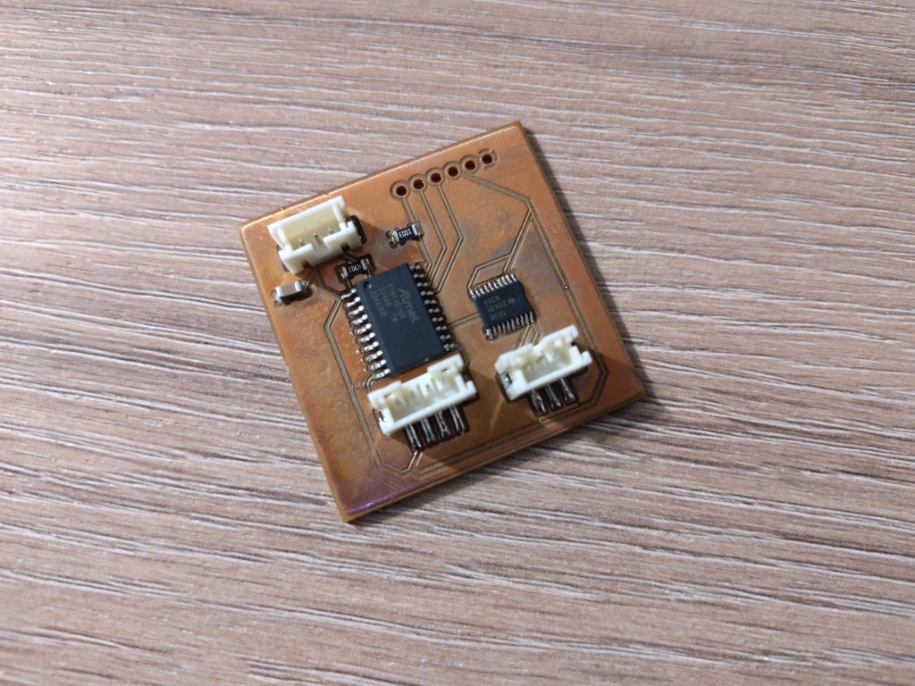
Due to other commitments, I unfortunately don't have time for FabAcademy at the moment, so I've made things very easy for myself this week. In addition to the group assignment, which I used to calculate the power consumption of the WS2812b LEDs for planning and sourcing my power supply for the final PCB, I also controlled them with my own board, as that is my plan for the final project.Unfortunately, contrary to my plan, I couldn't use the board from the previous week to work with the WS2812b LEDs because errors crept in. Being the smart person I am, I figured that since I had to make a new board anyway, I could incorporate the networking part. Accordingly, I designed and built the following board. I thought it would be smart to control the LEDs via an ATTiny. While programming, I discovered that this isn't necessarily the case. I would like to fully work with the LEDs, but unfortunately, the ATTiny can "only" work with a stripped-down library. Additionally, when uploading the program code, I discovered that I had another error on the board. I had installed the 470 ohm resistor on the UPDI line as a pull-up resistor rather than a series resistor.
Because I wasn't sure beforehand which method would work how well, I also installed the six-way cable so that programming could be done via MISO, MOSI, SCK, RESET, VCC and GND as standard. As you can see, the holes for this are far from pretty, but they are quite rare. This is because I forgot to select the holes when exporting in KiCad and unfortunately didn't notice that they were missing during the further process. Because I had little to lose, I tried drilling the holes myself using a pillar drill and a 1 mm drill bit. Unfortunately, this only worked very poorly; the result is known. The good news is that I learned how to use a soldering oven the only way humanly possible: by making mistakes. Note: Adjust the distance of the PCB holder before the interior is preheated to 170°C. Tip number 2: The circulating air is quite strong, so don't forget to secure the PCB in the holder. Tip number 3: 20TSSOP is small. Very small, in fact. Don't bother with it, it's no fun.
Second try
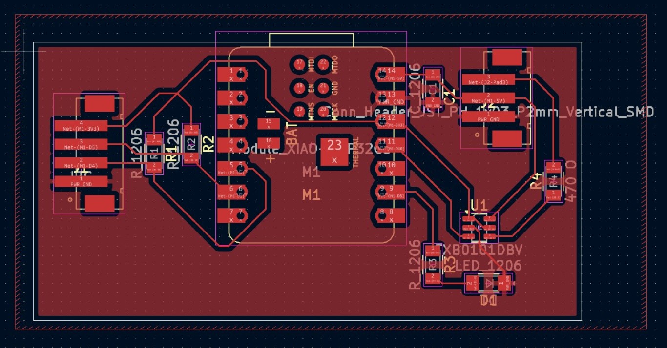
I'll skip the design process here; I described it in previous weeks. Here's my result from KiCad.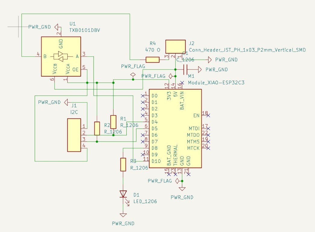
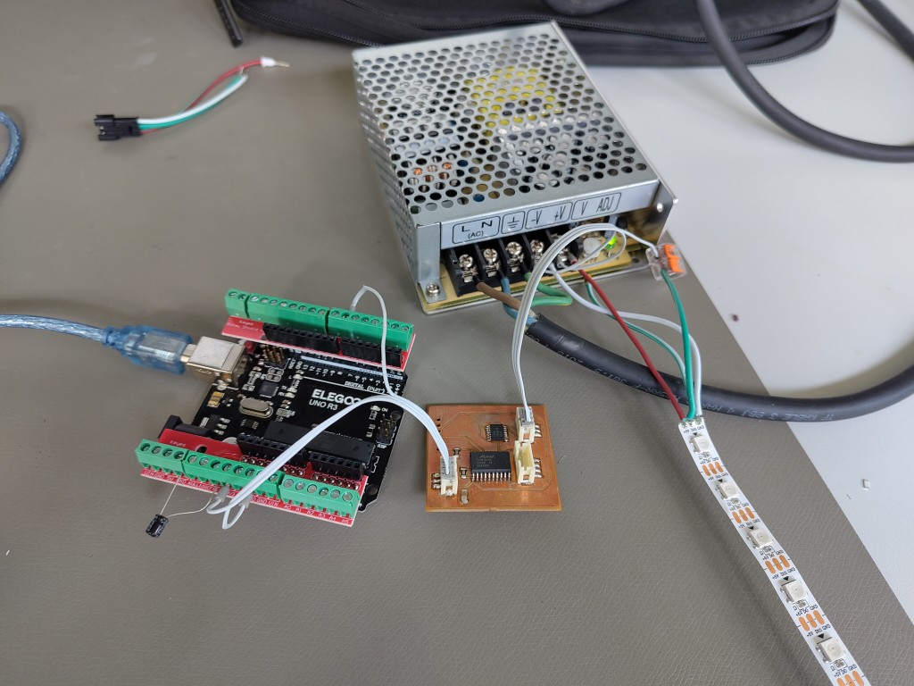
Similar to what will be done in my final project, the power supply is handled externally via a power supply and therefore connected to 5V via cable, although I'll be downsizing the power supply later and adding it to the board. I decided weeks ago to work with JST connectors and sockets because they save me the crimping process and I can simply press the ribbon cable in with a flathead screwdriver to make the connection. Therefore, these connectors are essentially the same on the board.
Starting at the top, I connect the 5 V from the power supply to the board, and next to it a control signal from the ESP to the LEDs, converted via a logic level converter. It is also important to match the voltage levels and connect the ground. On the left is the quad connector, where the two data lines for the I2C connection are pulled up to 3.3 V via 470 ohm pull-up resistors. At the same time, the 3.3 V is passed on to the ATTiny to supply it with power, as this connects the logic level depending on its input voltage. By using 3.3 V for this, I can avoid the need for logic level converters on the I2C lines. For debugging purposes, I added an LED via a series resistor, and that explains the board. This brings us to the next slideshow, the production of the board.
1 / 11
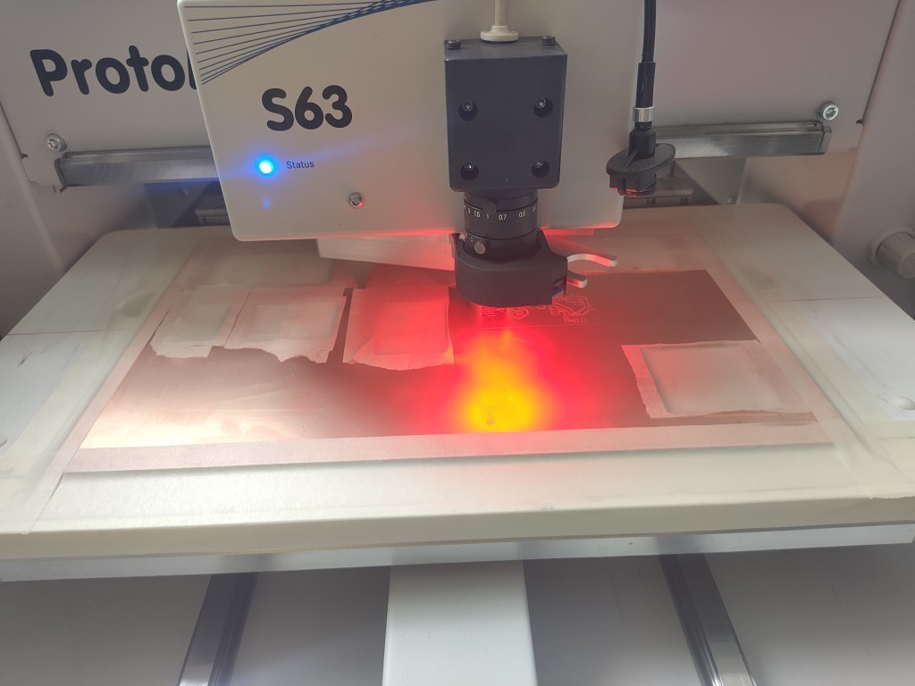
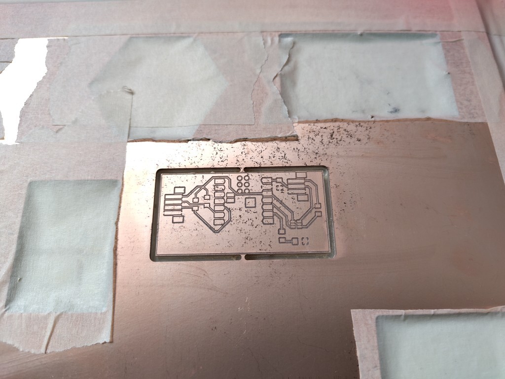
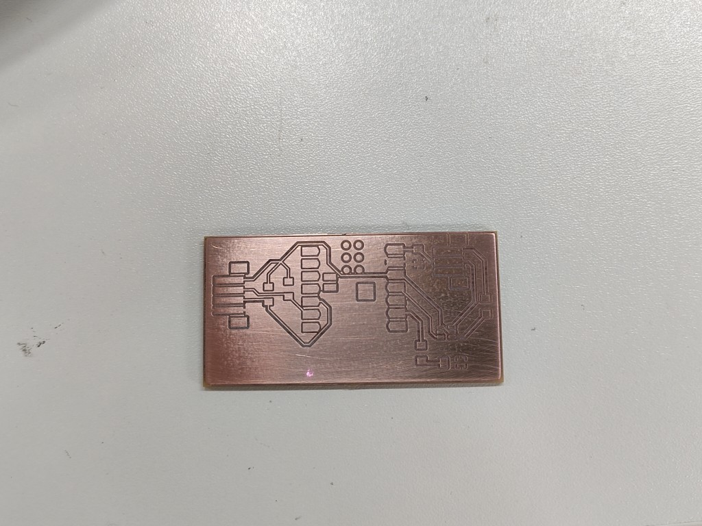
milling the board
2 / 11
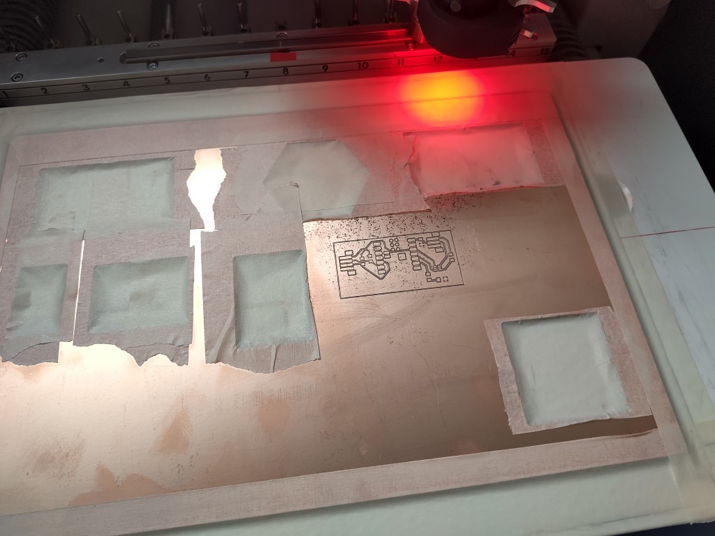
the milled result
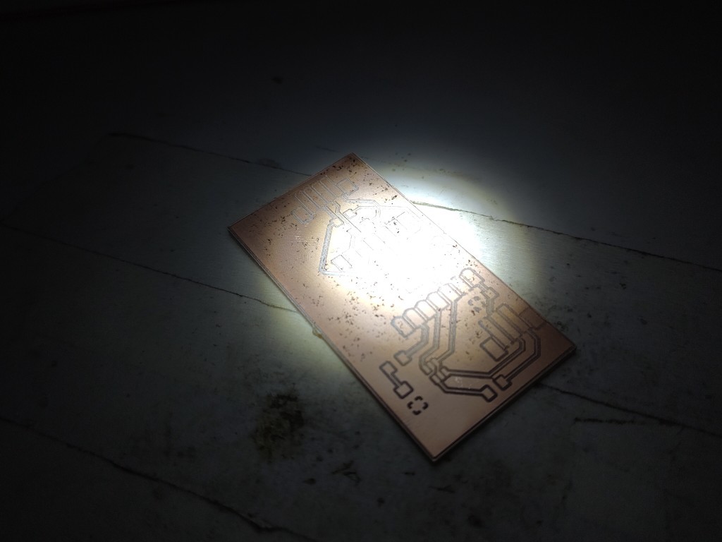
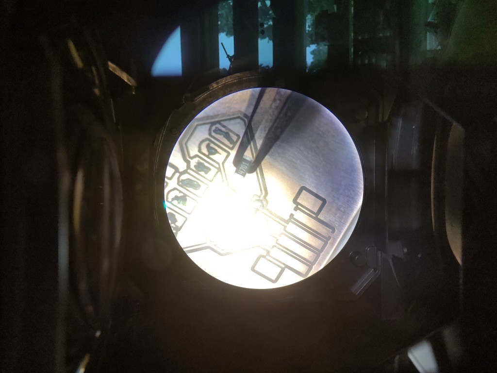
3 / 11
4 / 11
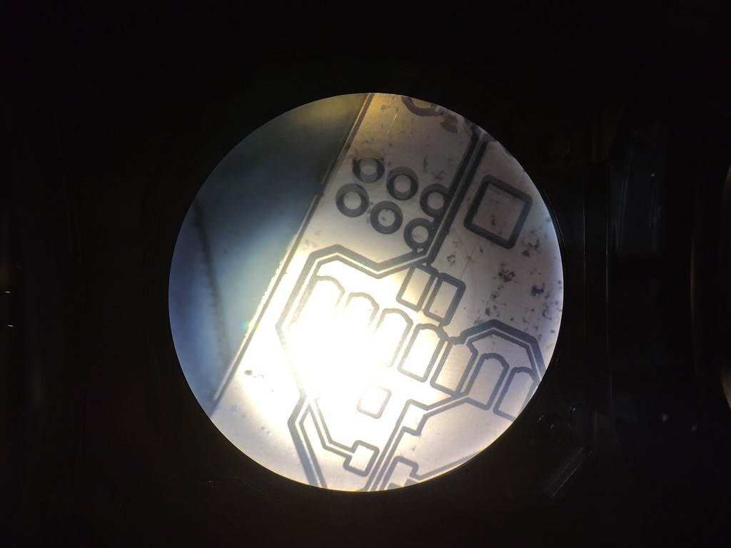
a quick check under the microscope
5 / 11
6 / 11
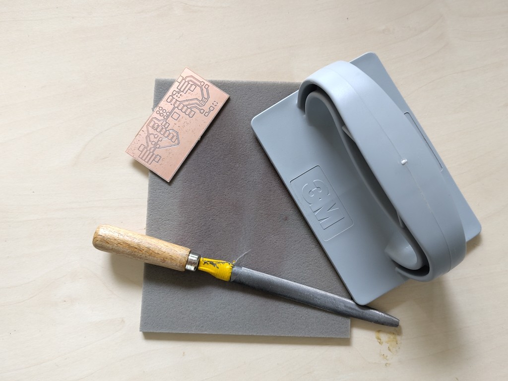
then it was time to rework
7 / 11
the reworked result
8 / 11
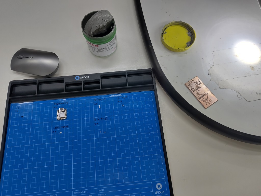
my arrangement for assembling the board
9 / 11
some pictures from assembling
10 / 11
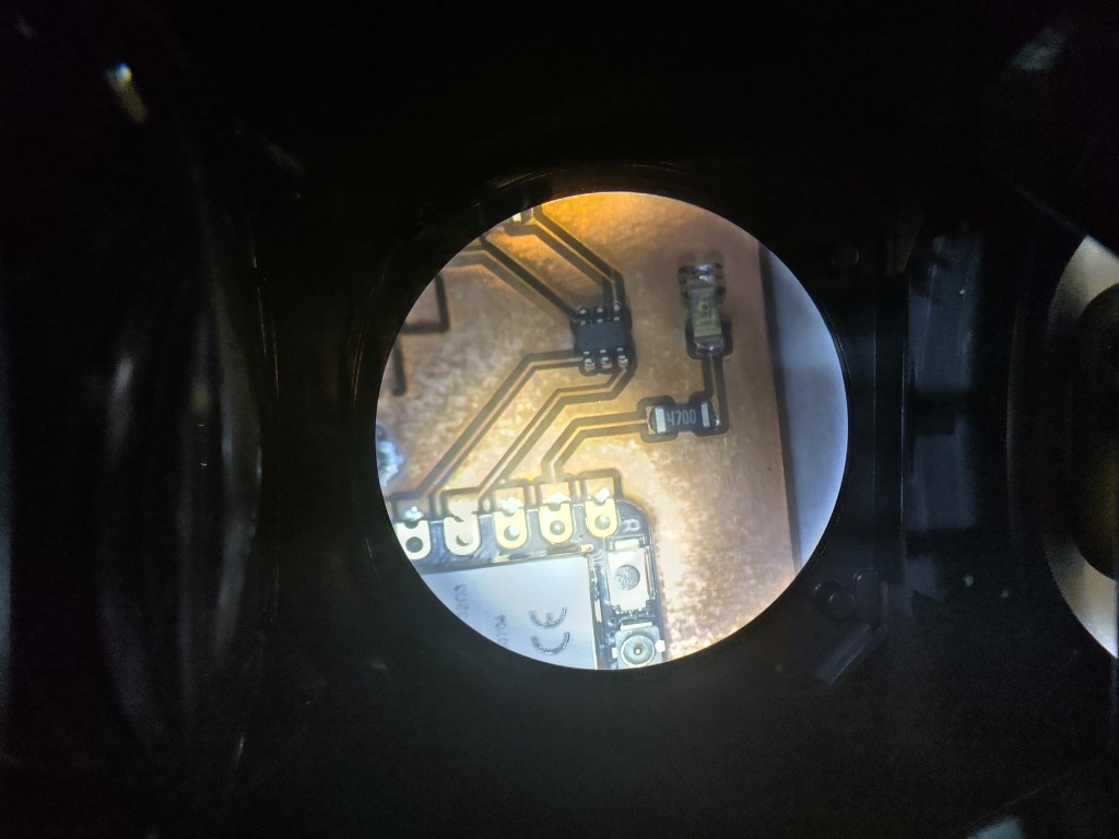
11 / 11
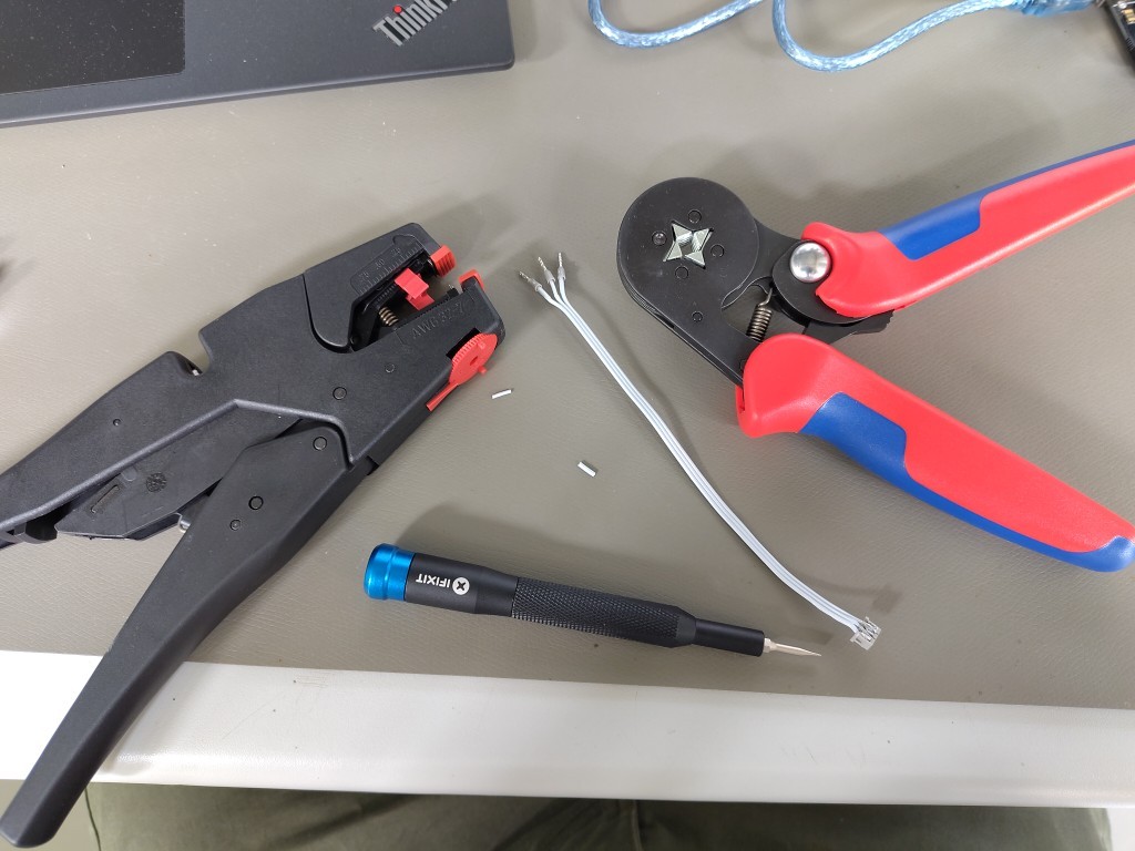
my equipment for making the cables
Unfortunately, I forgot to take more pictures afterward when I soldered the connectors at home. The workflow that proved most effective here was to coat the pads with flux and then pre-tin them with 0.3 mm solder. Then I put the connector on and use 0.7 mm solder to attach it. I don't want to rule out the possibility that there are better workflows, but this one runs super smoothly and efficiently.
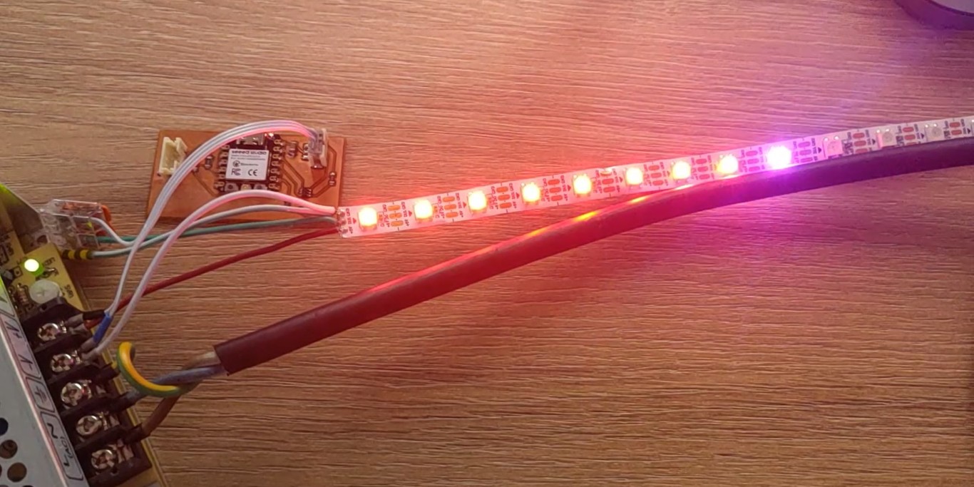
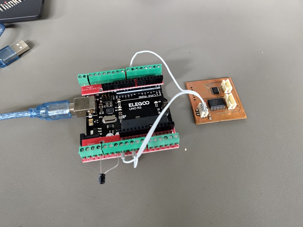
Because I was too focused on the rest of the wiring to think about taking pictures, I've dug out one I took with my first board. The wiring is still the same, but the reasons why it didn't work were different, as already described.
#include <Adafruit_NeoPixel.h>
#ifdef __AVR__
 #include <avr/power.h> // Required for 16 MHz Adafruit Trinket
#endif

#define LED_PIN    D10
#define LED_COUNT 10


Adafruit_NeoPixel strip(LED_COUNT, LED_PIN, NEO_GRB + NEO_KHZ800);

void setup() {
  #if defined(__AVR_ATtiny85__) && (F_CPU == 16000000)
  clock_prescale_set(clock_div_1);
#endif

  strip.begin();           // INITIALIZE NeoPixel strip object (REQUIRED)
  strip.show();            // Turn OFF all pixels ASAP
  strip.setBrightness(50); // Set BRIGHTNESS to about 1/5 (max = 255)
}

void loop() {
  colorWipe(strip.Color(255,   0,   0), 50); // Red
  colorWipe(strip.Color(  0, 255,   0), 50); // Green
  colorWipe(strip.Color(  0,   0, 255), 50); // Blue

  theaterChase(strip.Color(127, 127, 127), 50); // White, half brightness
  theaterChase(strip.Color(127,   0,   0), 50); // Red, half brightness
  theaterChase(strip.Color(  0,   0, 127), 50); // Blue, half brightness

  rainbow(10);             // Flowing rainbow cycle along the whole strip
  theaterChaseRainbow(50); // Rainbow-enhanced theaterChase variant
}


void colorWipe(uint32_t color, int wait) {
  for(int i=0; i<strip.numPixels(); i++) { // For each pixel in strip...
    strip.setPixelColor(i, color);         //  Set pixel's color (in RAM)
    strip.show();                          //  Update strip to match
    delay(wait);                           //  Pause for a moment
  }
}


void theaterChase(uint32_t color, int wait) {
  for(int a=0; a<10; a++) {  // Repeat 10 times...
    for(int b=0; b<3; b++) { //  'b' counts from 0 to 2...
      strip.clear();         //   Set all pixels in RAM to 0 (off)
      // 'c' counts up from 'b' to end of strip in steps of 3...
      for(int c=b; c<strip.numPixels(); c += 3) {
        strip.setPixelColor(c, color); // Set pixel 'c' to value 'color'
      }
      strip.show(); // Update strip with new contents
      delay(wait);  // Pause for a moment
    }
  }
}


void rainbow(int wait) {
  for(long firstPixelHue = 0; firstPixelHue < 5*65536; firstPixelHue += 256) {
    strip.rainbow(firstPixelHue);
    strip.show(); // Update strip with new contents
    delay(wait);  // Pause for a moment
  }
}


void theaterChaseRainbow(int wait) {
  int firstPixelHue = 0;     // First pixel starts at red (hue 0)
  for(int a=0; a<30; a++) {  // Repeat 30 times...
    for(int b=0; b<3; b++) { //  'b' counts from 0 to 2...
      strip.clear();         //   Set all pixels in RAM to 0 (off)
      for(int c=b; c<strip.numPixels(); c += 3) {
        int      hue   = firstPixelHue + c * 65536L / strip.numPixels();
        uint32_t color = strip.gamma32(strip.ColorHSV(hue)); // hue -> RGB
        strip.setPixelColor(c, color); // Set pixel 'c' to value 'color'
      }
      strip.show();                // Update strip with new contents
      delay(wait);                 // Pause for a moment
      firstPixelHue += 65536 / 90; // One cycle of color wheel over 90 frames
    }
  }
}