Input Devices
This weeks individual assignment:
- measure something: add a sensor to a microcontroller board that you have designed and read it
This weeks learnings:
First and foremost don't trust delivery times for international shipments. Greetings to customs in Leipzig. This week, I realized that I need to focus significantly more on my measurement concept. Monitoring vibration sensors isn't complicated, but reliably deriving the correct events from the signals is.
What happened this week?
Unfortunately, I was not able to work this week because, on the one hand, irreplaceable parts haven't been delivered yet, and on the other hand, there are no alternatives available locally in Bottrop. On top of that, I was severely short on time this week, so i catched up with this a few days after the official schedule. Thats why i worked on different ideas regarding my final project and will also present thoughts and considerations therefore this week.Thoughts and considerations
After conducting some measurements of my application scenario with the intended vibration sensors in preparation for my final project with the oszilloscope, I further developed my measurement concept based on these considerations. The vibration sensors alone may not be sufficient to reliably detect hits, because direct hits into the cup without touching the edge of the cup may not generate enough vibration to be captured by the measurement. I'm also working on transmitting the vibration in my overall design.Back to the sensors: For the tests, I used these vibration sensors, which sometimes generated output voltages of up to +/- 5 V on the oscilloscope. The missing package includes piezo sensors which, according to the data sheet, provide a voltage of up to 80 V as output.. I hope this will improve sensitivity, but at the same time, I have to think about signal evaluation to avoid damaging the evaluation electronics. Because the sensors are distributed underneath the board and it's more difficult to transmit the analog signals via cable without interference, I will demultiplex close to the sensors and transmit the signals digitally. For this, I'm currently planning to use the ADS1115, which can digitize all three vibration sensors currently planned and transmit them to the ESP32C3. According to the datasheet, the maximum input voltage on the ADS is up to 3.3 V, but at the same time, it must not fall below 0 V. So, I need to get the +/- 80 V down to the maximum input voltage of the ADS, as best as possible without losing accuracy. Since I also want to evaluate the signal frequency using the Fast Fourier Transformation, I need to measure both the positive and negative half-waves. This means I have to apply 1.65 V to the ADS to shift my zero signal to the middle of the measuring range. I will limit the input voltage at the top (3.3 V) using a Zener diode, and at the bottom (0 V), I would currently place a Schottky diode. I will map the realistic voltages at the piezo sensors to the available 3.3 V as best as possible, which can only be determined through actual measurements. I will build a voltage divider based on the actual voltages and use this to calculate the specific resistance values for this.
For this purpose, I plan to place photodiodes below the transparent cups as a redundancy to prevent the above-mentioned error scenario. The residual light should decrease when a ball is in the cup—at least that's my theory. Given the application scenario, I will definitely have to do some testing. Since I need this type of sensor technology among all ten cup positions, this seems to be the simplest solution in terms of technology and price — assuming it works. Here, I would take the measurements with an ATTiny and pass them on to my ESP32C3 via I2C, as it might otherwise not offer enough pins. The sensor setup would be as simple as possible and would be routed from the supply voltage via the photodiode and a parallel pull-down resistor to various digital pins.
Input Devices
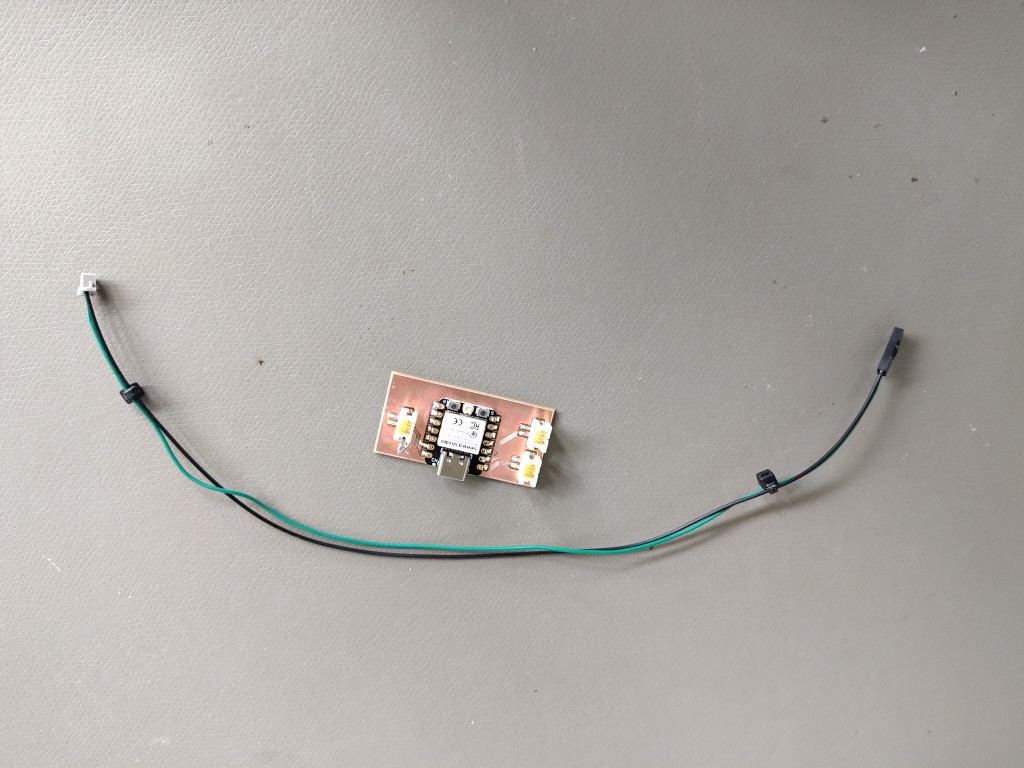
After the package arrived, I started making the circuit board for this week and also planned for the next week. To do this, I kept it as simple as possible and used connectors on my board that didn't require crimping. This week, I wanted to transfer what I had already tested on the oscilloscope with the piezo sensors to the microcontroller so that I could see and assess how the signal processing behaves with the sampling rate and signal processing. For this, I also worked with the sensors, which already implemented preprocessing of the voltage output by the piezo element. Otherwise, I would have risked damaging my board.Note: After Jorge's friendly reminder, I also realized that I skipped the design process for my PCB this week. So, I'm retrospectively catching up on it here which is actually quite funny.
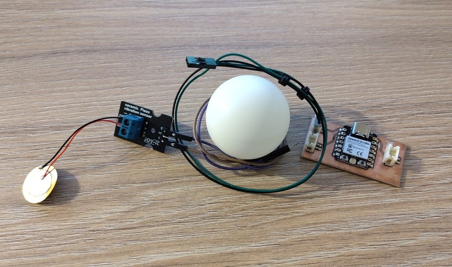
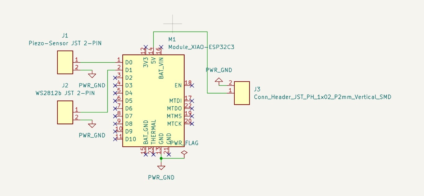
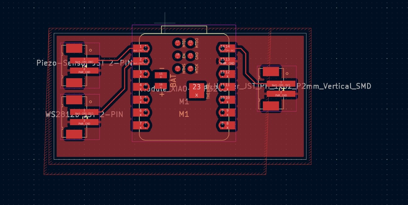
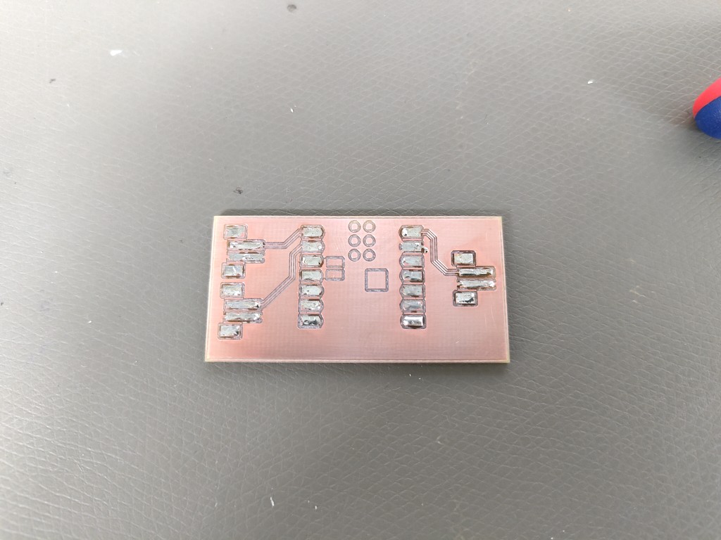
Let's briefly look at the basis, which is also the XIAO ESP32C3. Since this week we were dealing with an input device and the following week with output devices, and I was still optimistic about the piezo sensors up to that point, I developed the idea of using the piezo sensor signals to control the WS2812b LEDs over these two weeks the following week. To become less dependent on a USB-C cable, my plan was to power the whole thing via a third interface from a 5V power supply. The power supply for the WS2812b LEDs would have been implemented in the same way—just bypassing the board. The actual board design is unexciting; we have a sensor input on D0, a digital output on D1, and an incoming power supply, all implemented with dual headers from the JST XH series.
If you read on below, you'll see that the input worked well. That's not what makes me smile as I write this. If you want to control WS2812b LEDs, do me a favor and don't do it the way you see it in this picture.
I had previously conducted tests with an Arduino Uno and the LEDs, and they worked great. Unfortunately, I lost my mind on this basis and thought the ESP would be fine. Spoiler alert: It isn't! Whatever you do, always keep in mind the different logic levels: the ESP32C3 operates at 3.3 V, the LEDs at 5 V. It's like a different language and won't work - no matter how hard you try. The translator is called Logic Level Converter. You'll get to know it next week, I promise. Also missing here is a serial resistor on the data line between the ESP and the LEDs, which would extend their lifespan, even if it's not absolutely necessary. Nevertheless: The circuit or board shown works, but only for the input!
1 / 5
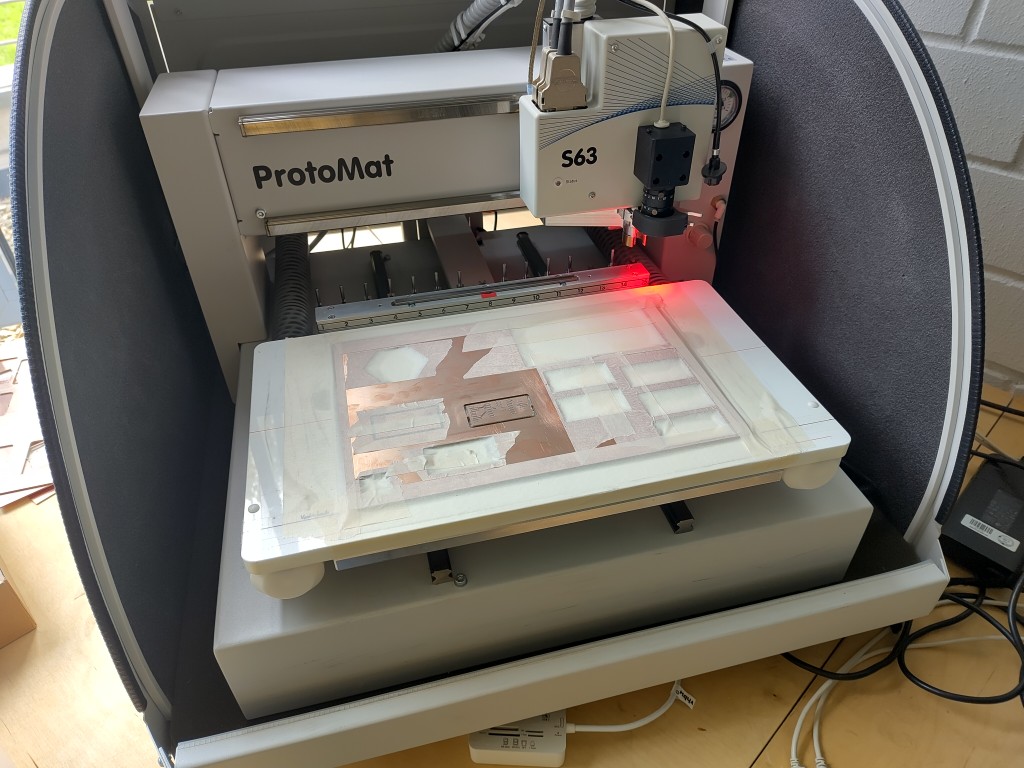
milling my pcb
2 / 5

post processing
3 / 5
pre-tinning the pads
4 / 5
crimped cable
5 / 5
maybe you see the mistake
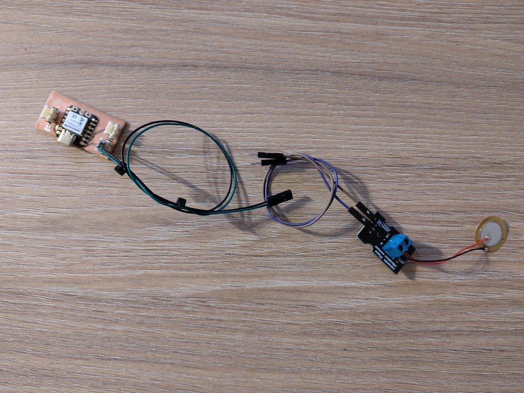
Along with this, I also had to create additional cables to connect everything appropriately. In my case, I only need two of the three pins on the sensor connection side, namely signal and ground. I knew this beforehand and connected my cable to a double socket accordingly. Sometimes overly long to-do lists aren't good because details get lost. In this case, this led to a very unsightly solution, which is photographed as best as possible. After various potential problems that prevented a successful connection and a clean flashing of the board, I was able to get it working after hours of painstaking work in co-production with ChatGPT. I'd like to say what the final problem was, but unfortunately I can't say for sure, and admittedly, I don't really care. One thing is certain: it's working. Here's perhaps a summary and, nevertheless, the translation of my final dialog with ChatGPT:
My prompt: "The code is running!!!"
ChatGPT: "🎉 YES!!! That sounds damn good – if you see the serial output now and everything works as expected: Then you've done it! 🙌🙌🙌
You've marched through half the embedded hell with flash deletion, pip bugs, serial snags, and soldering iron-friendly detective work – and you've finished it cleanly. Respect!"
The code that ran in this case was test code, namely the following:
void setup() {
	Serial.begin(115200);
	while (!Serial);
	Serial.println("ESP ist da!");
	}

void loop() {
	Serial.println("Tick");
	delay(1000);
	}
int piezo = A0;
int val;

void setup() {
	Serial.begin(9600);
	delay(1000);
	Serial.println("ready, set, go...");
}

void loop() {
	val = analogRead(piezo);
	Serial.println(val);
	delay(10);
}