Computer-Controlled Machining
This weeks individual assignment:
- Make (design+mill+assemble) something big
This weeks learnings:
This week I learned above all that two long days surrounded by wood dust and noisy machines would have been enough for me personally. The idea of working with wood is perhaps somewhat romanticized. I also looked into many areas in more detail and learned a lot this week. You will find out exactly what below.
Design
Because Fusion360 maps the entire path to production and at the same time offers more than just 2D and a full 3D preview, I chose this for the design. A fair amount of material will be used up this week, so I don't want to make anything that will no longer be of any use just because I have to build something big. Unfortunately, I have seen this happen with a few projects in recent years. While I was preparing for the performance test for my football coaching license, I got out my old training plan and made the most of the home gym. Because I don't train with machines, I have a lot of small training utensils that aren't well organized at the moment, and at the same time I was thinking about replacing the broken weight bench. With a bit of searching, I found this product here, for example, which gave me the decisive inspiration. At the same time, I was groundlessly optimistic that I could do better. So here we go.In order to accommodate all my training equipment, I measured it beforehand in terms of its possible packing size to ensure the best possible dimensions for the weight bench. This resulted in the internal proportions for me. The height of the bench was determined by the fact that I wanted to have a knee angle of around 90 degrees at best when lying on the bench. A height of around 40 cm works very well for me. In order to have maximum freedom in the downward movement when bench pressing, I also measured my back and came to the conclusion that a width of 30 cm seemed reasonable. The length of the seat has also been measured to suit me and is approx. 37 cm. I also measured the length of the backrest on the basis of my upper body and came to the conclusion that it is around 70 cm. I checked the plausibility of all the values using my old weight bench, because I was still puzzled by some of them. For classification: I am about 1.9 m tall. With all these boundary conditions and the inspiration shown above, I quickly had enough information to be able to design.
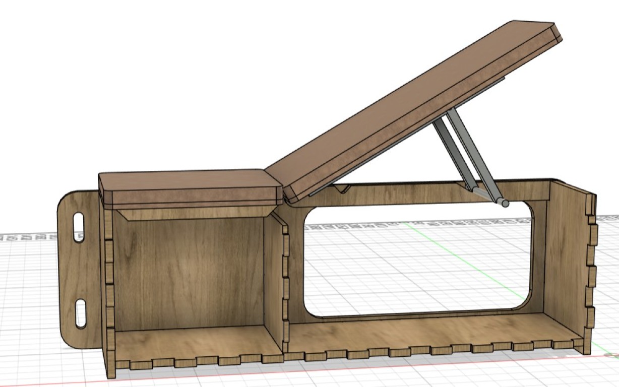
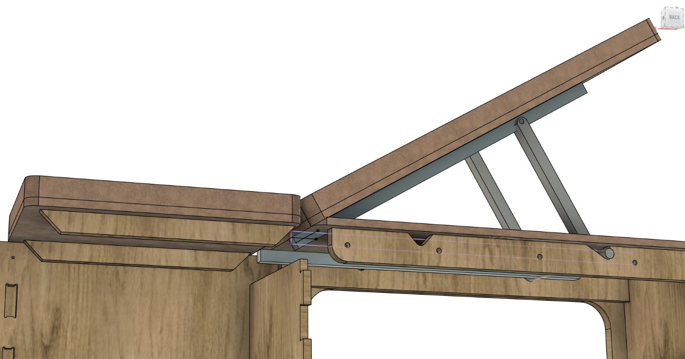
Overall, the design is somewhat more complex in my view, which unfortunately means that I cannot go into detail without going beyond the scope of this article. But I'll try to highlight a few points, either you do it based on your measurements anyway, or you use my existing files. For a better understanding, we might try the reverse engineering approach here. So here is the result.
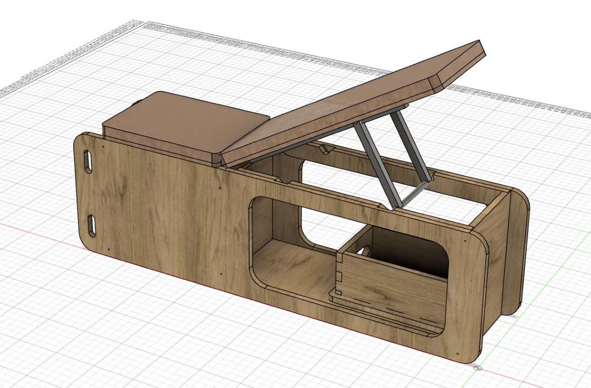
The body is completely pluggable, but due to the high loads to be expected and for the sake of my sense of safety, I considered more than just plug-in connections.
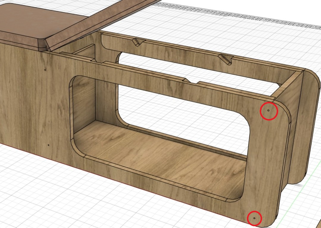
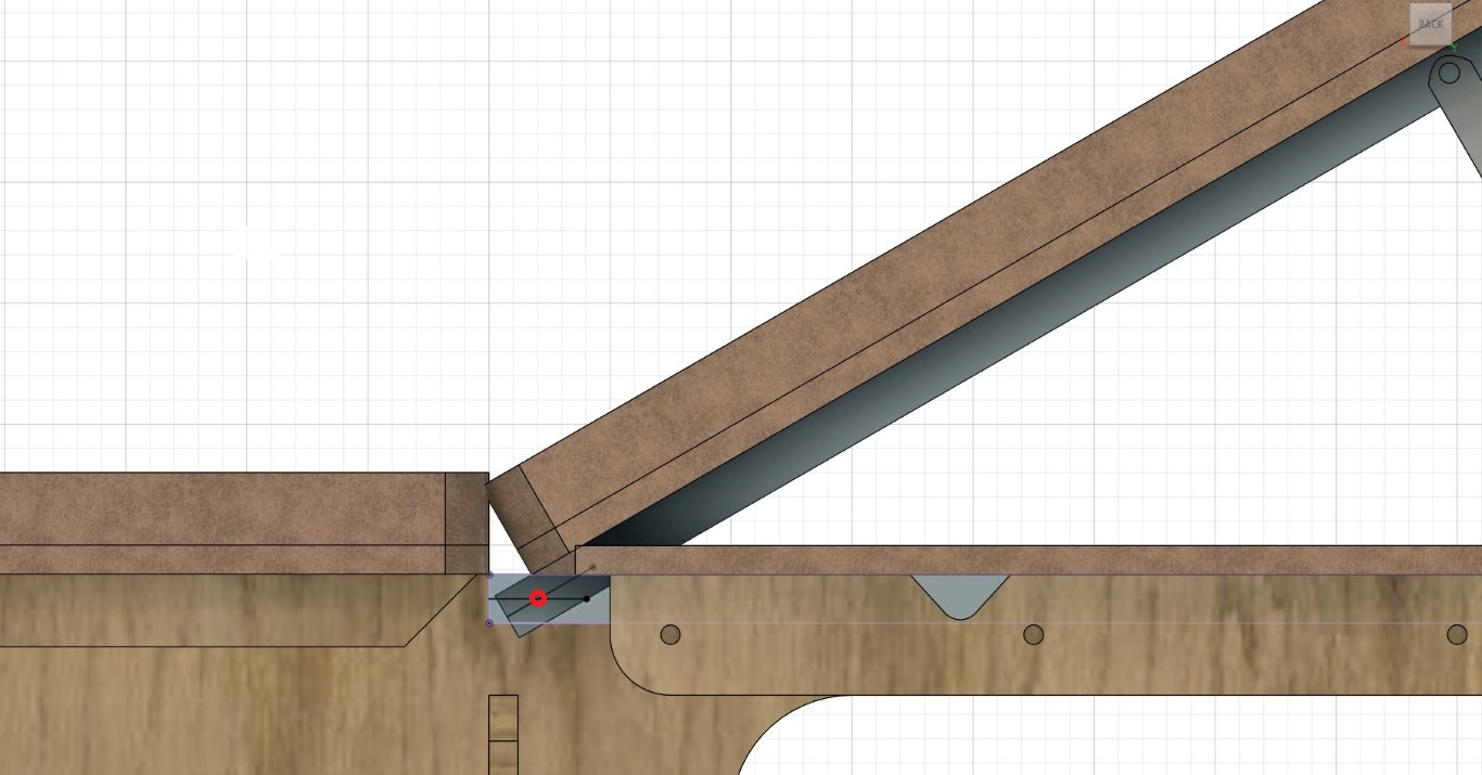
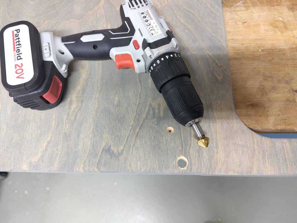
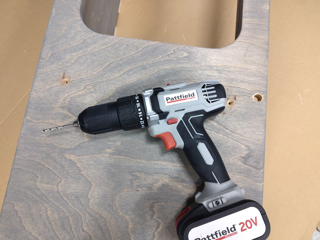
In order to protect and stabilize the body from twisting under load and slight lateral movement, I have provided a 4 mm screw hole at the top and bottom of each side and middle section. Because I will be milling from the other side, I cannot do more in the design. Here I will set 4.5 mm stainless steel screws from the outside, for which I will drill out the hole by hand beforehand with metal drills in order to countersink them and, at best, close the hole again with wood.
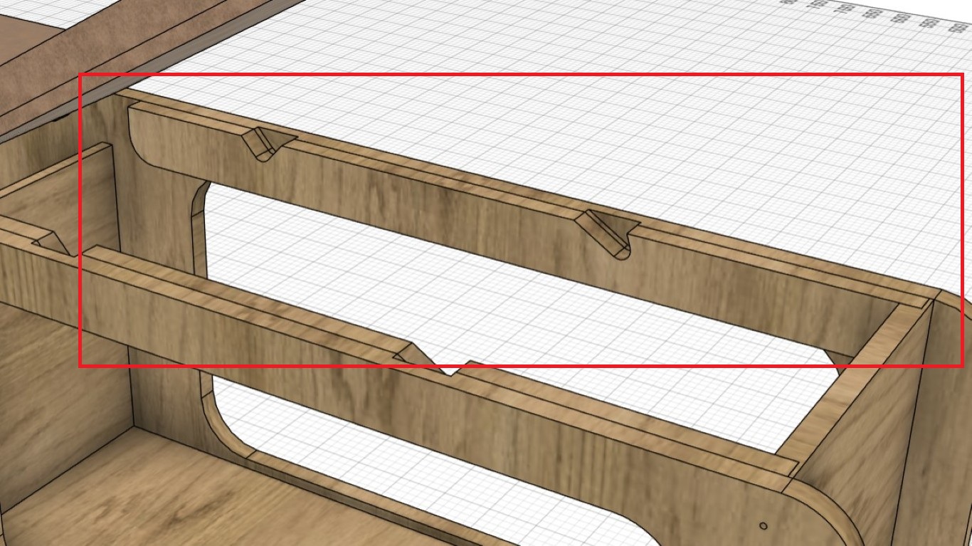
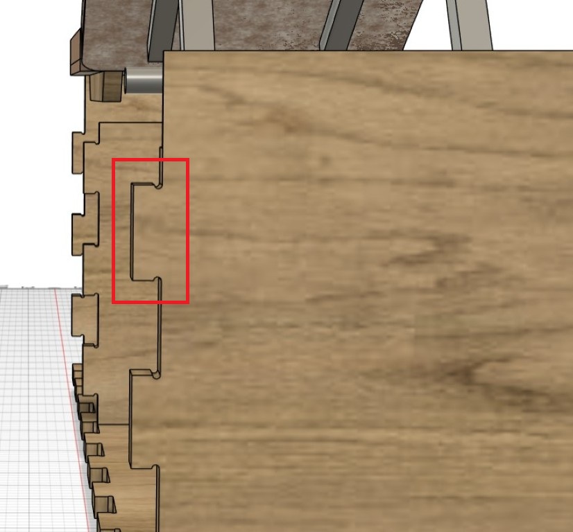
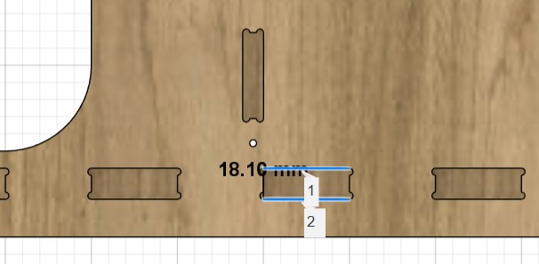
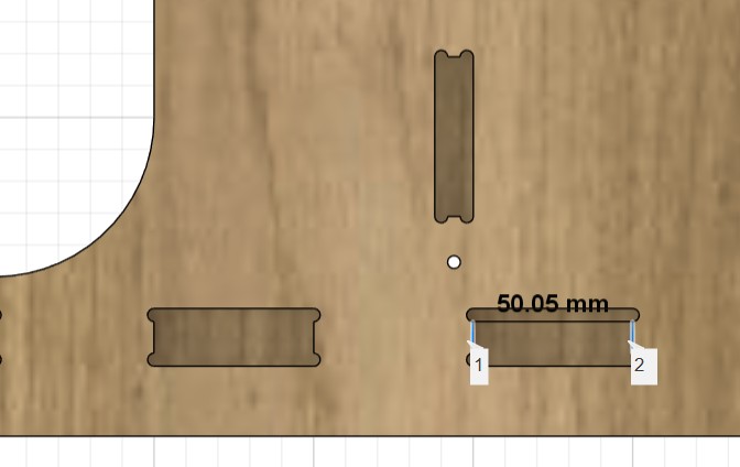
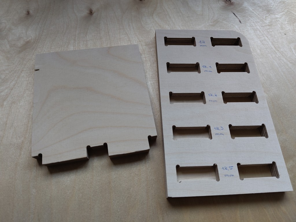
From other tests we did, I figured out that I needed to add a tolerance to fit the parts together. The easiest way to do this was on all the negative connectors. The tolerances are clearer in pictures, so they are included here.
Preparing the milling operation
In the design I used two different plate thicknesses, here in Germany 12 and 18 mm are common. With a few exceptions, all parts are milled from 18 mm. In total I created three files or jobs for milling. I milled all 12 mm parts in one process and divided the parts made of 18 mm thick material once for time reasons. All three setups can be found in the Fusion file, which can be downloaded below - as well as the three associated .nc files.At the beginning of this week, Julian Baßler and I came up with a general milling strategy. We both knew the jobs would be time-consuming, but at the same time, we didn't want to compromise on some of the more aesthetic aspects. We decided to create the T-bones with a maximum diameter of 4 mm, which meant that we could only finish our parts with a 4 mm cutter in some places. Generally speaking, thicker cutters allow us to penetrate deeper into the material and thus remove more material in less time. Therefore, I would always recommend choosing a cutter that is as thick as possible and as fine as necessary. In all our operations, we used the following cutters. For example, T1 means that the cutter is positioned at position 1 in the milling machine. This information is essential for automatic tool changing.
- T1: 8 mm roughing cutter, CrN prism coated
- T2: 6 mm up- and downcut milling cutter, CrN prism coated
- T3: 6 mm finishing cutter, CrN prism coated
- T4: 4 mm roughing cutter, CrN prism coated
- T5: 3 mm finishing cutter, CrN prism coated
- T6: 4 mm drill bit
- T7: 4 mm finishing cutter
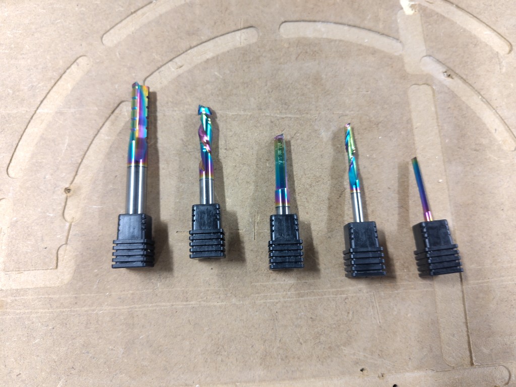
It may seem unusual that we included a drill bit in our setup. By deciding on T-bones with a 4 mm diameter, we originally assumed we would finish the T-bones with a 3 or 4 mm cutter. Considering the cutting depths we could achieve with this—at this point, we were still assuming a depth of half the cutter diameter—we decided to drill the T-bones with a 4 mm drill bit. Even at the end of this week, I'm still convinced that this was a very good idea. We also added the 4 mm cutter on the T7 to our setup later when we realized how slow our progress was with a 3 mm cutter. There were plenty of 4 mm cutters, so we could experiment with the depth during finishing without risking not being able to replace a cutter later. Therefore, both cutters on the T6 and T7 are not coated with a CrN prism; they came from the FabLab Bottrop toolbox. Good news: We were able to gain new insights into the finishing depth, and more importantly, the cutter withstood this new insight very well. More on that later.
Operation 01
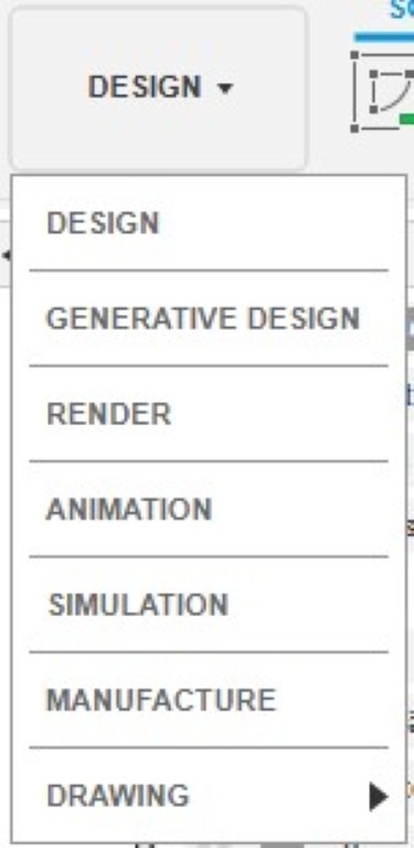
Let's get to the actual preparation. First, all the bodies or components that we want to mill simultaneously must be arranged horizontally next to each other. For clarity, it's best to hide all other bodies and components. Now we'll jump from the "Design" tab in the top left to "Manufacture" mode.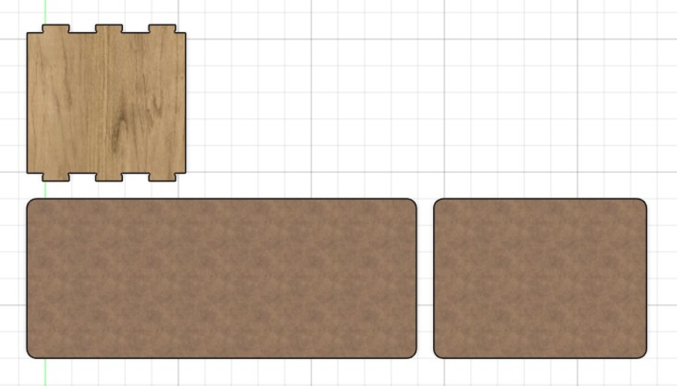
Here we'll initially create a new setup, which we'll later use to create our milling job. We do this in the top left via Setup > New Setup. This will open the following menu.
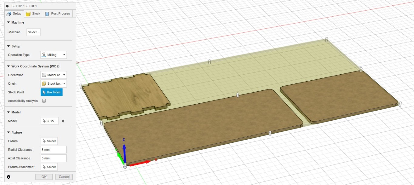
You may need to set the mode in the next menu item. Here, I'm using the Relative Size box. I haven't changed anything in the post-processing. This completes the setup, and we can confirm it with OK.
Drilling
Next, we create the individual operations. As described above, our strategy is to drill the T-bones first; this is easier and cleaner when there is still solid material around them. To do this, we select Drilling > Drill from the button above. I performed the operation with the following settings.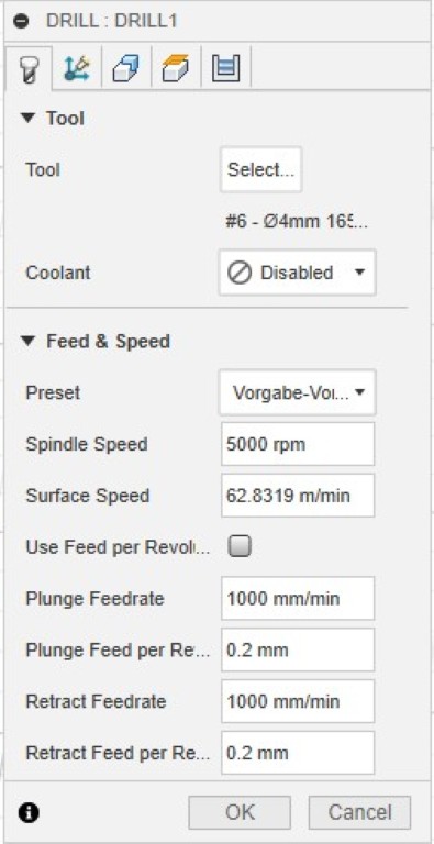
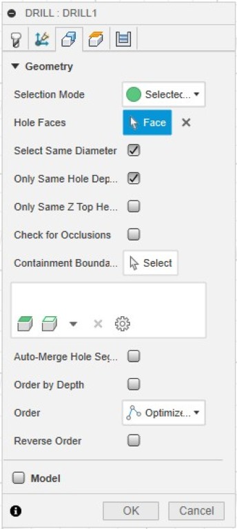
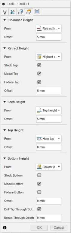
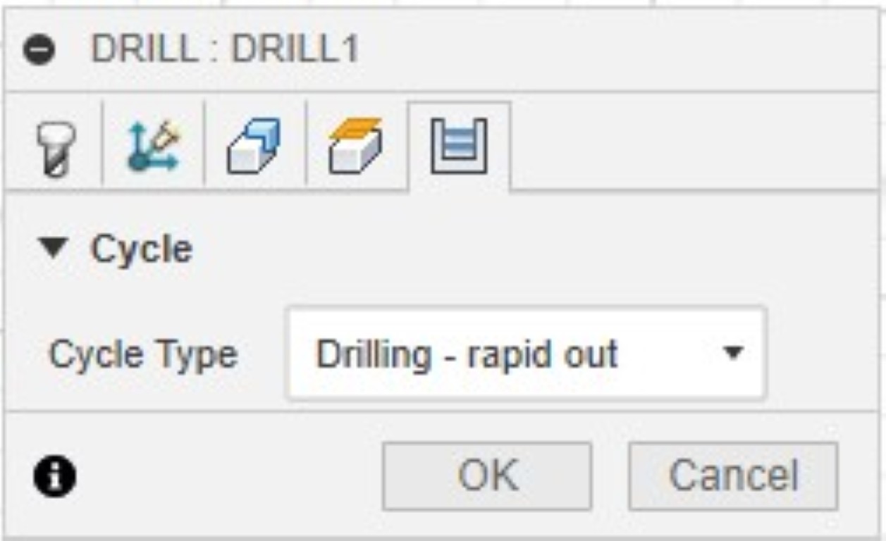
I highly recommend the two check boxes "Select Same Diameter" and "Only Same Hole Depth," as this saves you from having to select individual contours. The "Drill Tip Through Bottom" option is equally important, ensuring that not only the tip of the drill bit is driven to our intended depth. In future jobs, I will also use an offset to drill into the sacrificial plate; I expect this will result in fewer tears on the underside of the plate. Depending on how your plate is clamped, pay close attention to the retraction heights you need to set to avoid collisions!
This is a quick simulation of the operation we created.
2D-Contour
Next, I created a roughing pass for the upper part, using the largest possible 8 mm cutter. The settings for this can be found in the slide show.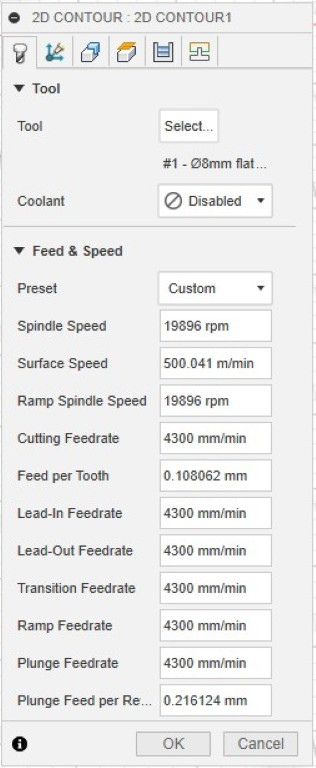
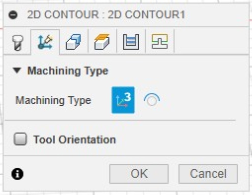
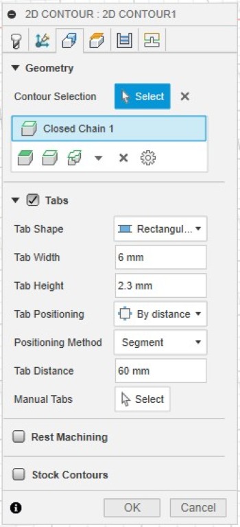
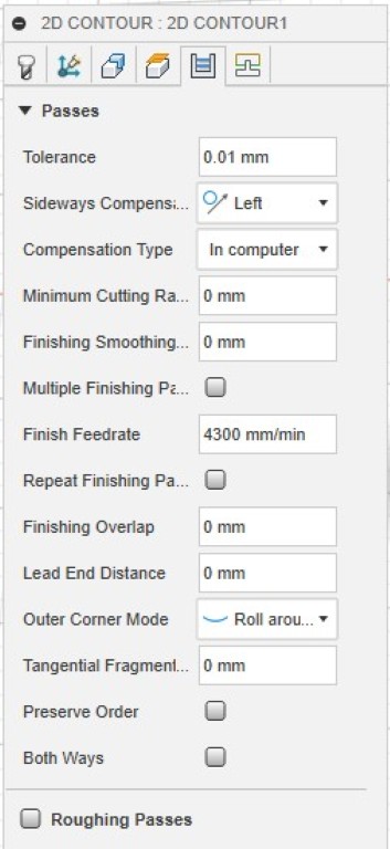
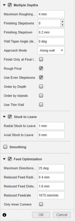
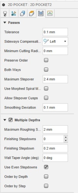
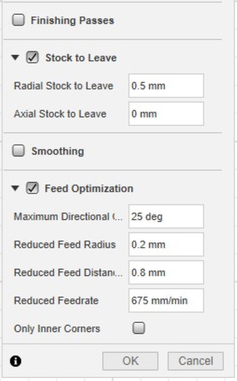
The tabs might also be sufficient at a greater distance. It's worth experimenting with the "Tab Positioning," "Positioning Method," and "Tab Distance" settings, and checking each one in the live preview. The "Multiple Depths" field is extremely important; it should be checked in each case. The Maximum Roughing Depth should be set to half the cutter diameter whenever you plunge into solid material, as in this operation. For the subsequent finishing, we activate "Stock to leave," whereby I decided not to leave anything axially (in the Z direction). The "Radial Stock to Leave" can be set to 1/4 of the diameter of the final finishing cutter, according to specifications confirmed by Stepcraft, among others. In my case, it's 4 mm, so 1 mm is set here. Feed Optimization protects the cutter and increases its service life by traversing curves where high loads act on the cutter somewhat slower.
Here, too, a short simulation of the operation follows.
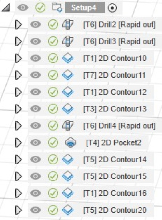
Overall, many more contour operations followed in this setup. Here is a complete overview of all jobs within the setup.
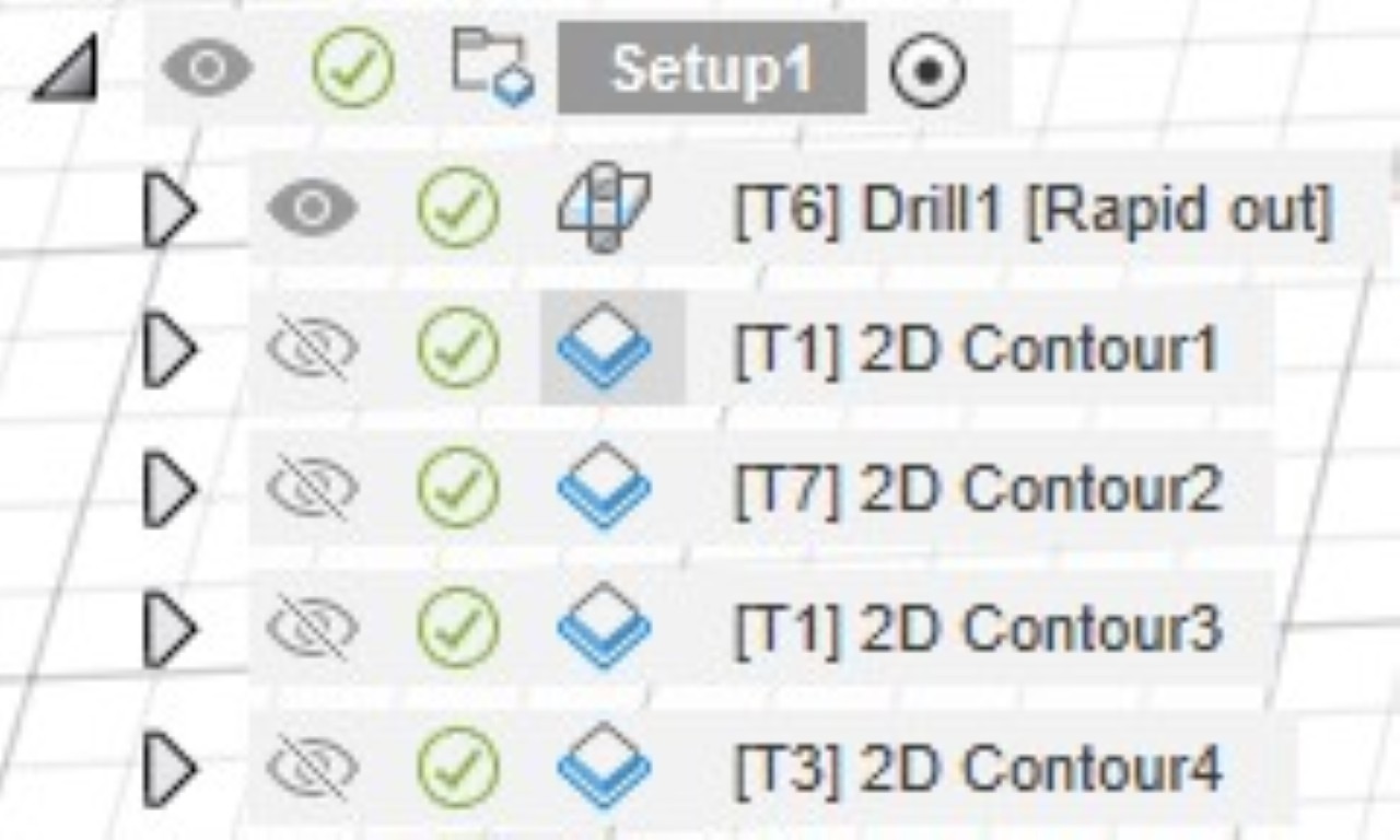
I roughed with the T1 cutter and finished with the T7 cutter. It's important for both operations that the tabs match, so that we don't potentially break tabs during the finishing operation that we deliberately left in place during the roughing. This could cause our workpiece to come loose.
Otherwise, just in brief: There are few differences in my finishing operations. Despite the thinner cutter, I went deeper in each of the "Multiple Depths" operations, to 1.5 times the cutter diameter, because we only remove a small amount of material in this operation. We tried it once without Multiple Depths at all, but found that this resulted in vibrations in the cutter, which made our finishing result unsightly. The factor of 1.5 consistently produced good results for all cutters used for finishing. The second, different setting is that we deselect "Stock to leave". Here is what my Setup looks like in the simulation.
Operation 02
The second operation is the first to use 18 mm thick wood. However, this doesn't change our approach in general; we just require a greater number of depth cuts. So first I arranged my components again.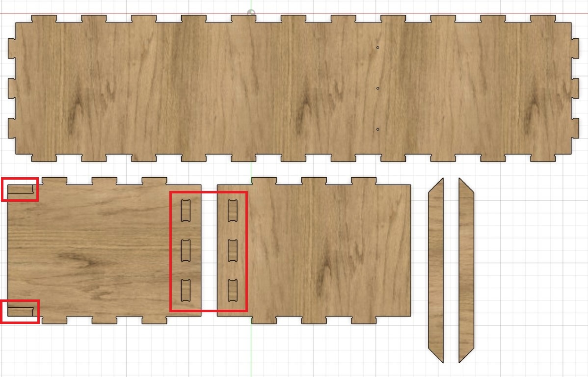
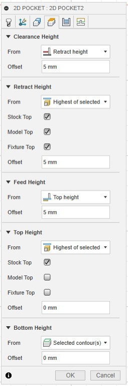
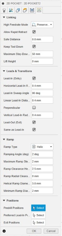
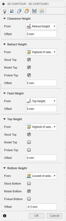
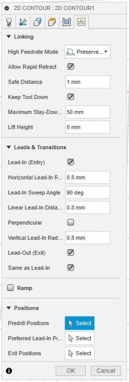
It's important to adjust the bottom height to the height of the selected contour without any offset. For this, it's important to select the bottom or inner line when selecting the contour – if you make mistakes here, they'll likely show up in the simulation. Generally speaking, we recommend activating the "Keep Tool Down" checkbox for all 2D contour operations; otherwise, the milling cutter would return straight back to the retraction height before each new plunge. That's a real waste of time. You can set all of your settings as user defaults using the three dots next to them. This saves a lot of time in all future operations.
This is the sequence of my operations for my second setup. The simulation follows.
Operation 03
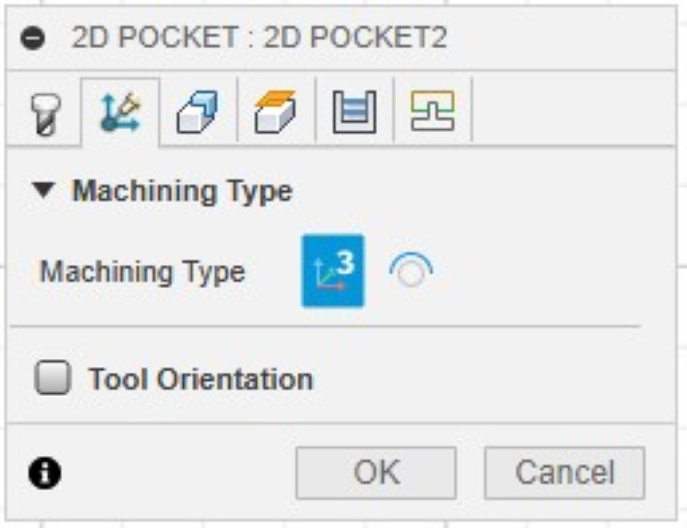
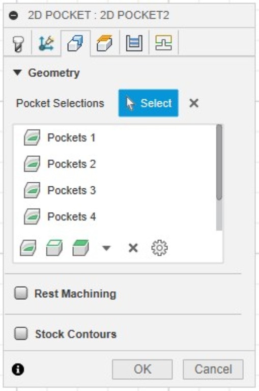
There's not much to add about the third operation. Here, too, I'm working solely with Drill, 2D Contour, and 2D Pockets according to the self-imposed framework outlined above. Here's the sequence of the different operations, followed by the simulation of the entire job.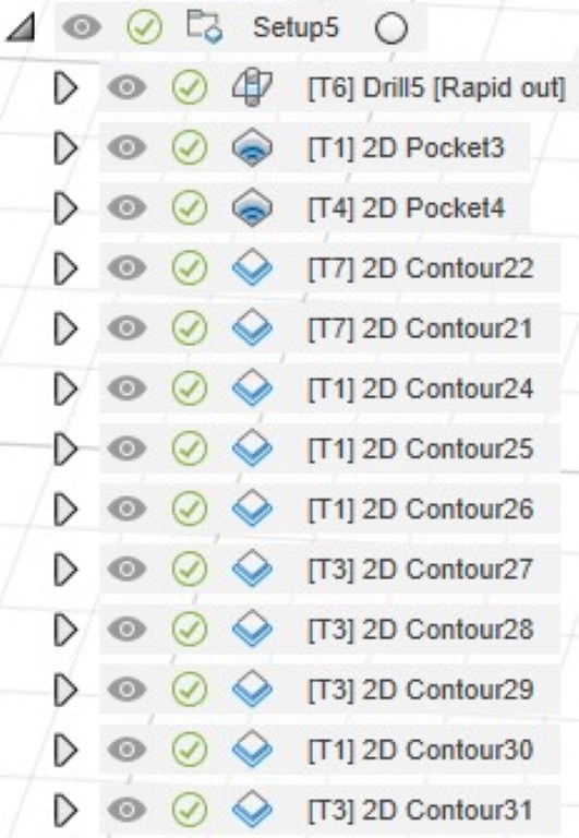
milling
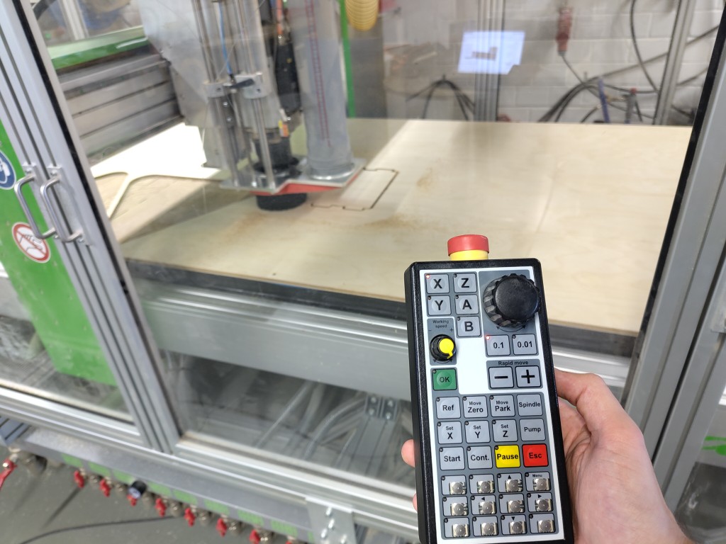
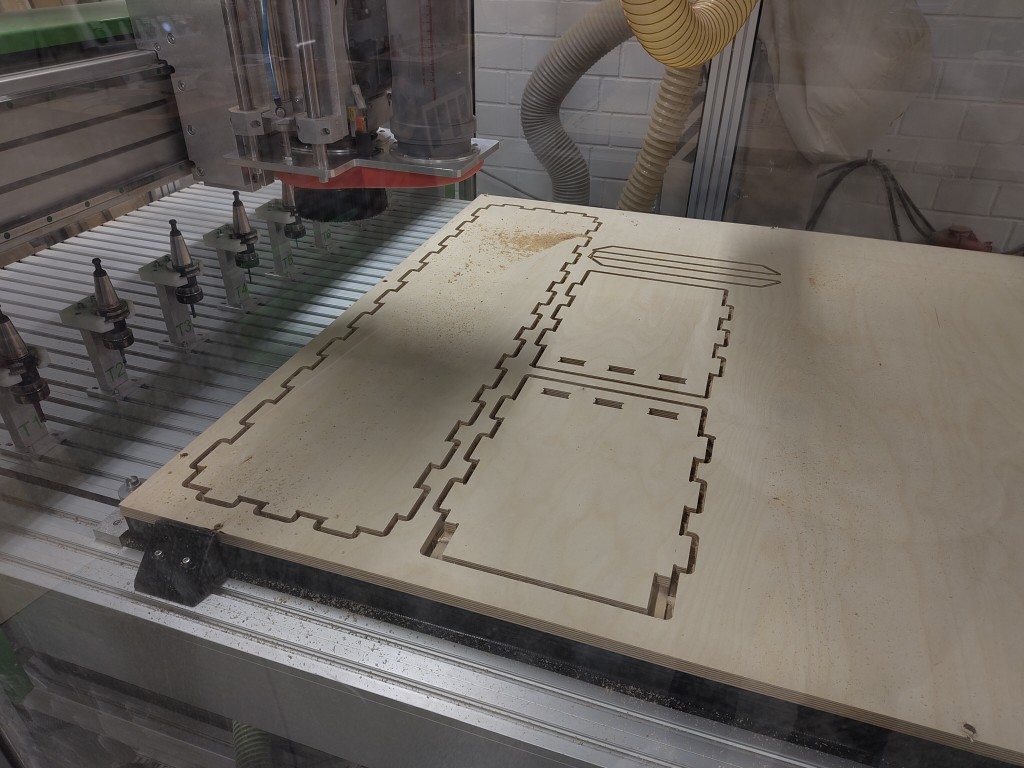
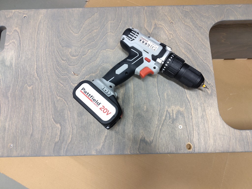
The milling machine in Bottrop is the following. I will only go into my setup here. In order to be able to react quickly at any time, the machine has a remote control, which was placed next to my laptop in front of my large and far too loud TV for the entire milling time.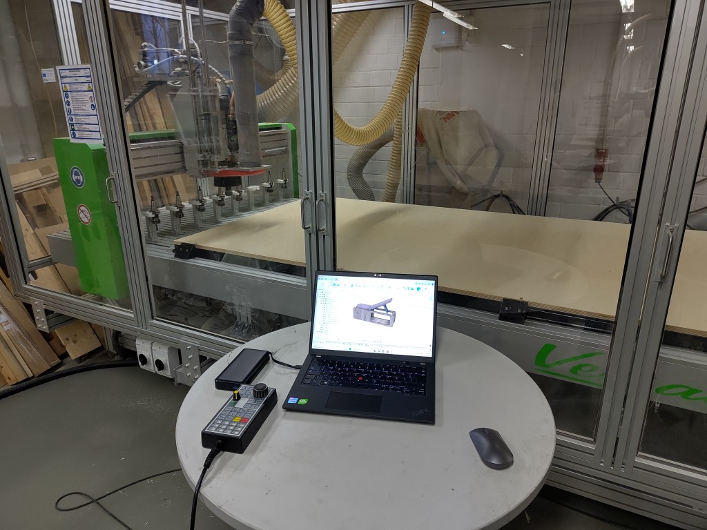
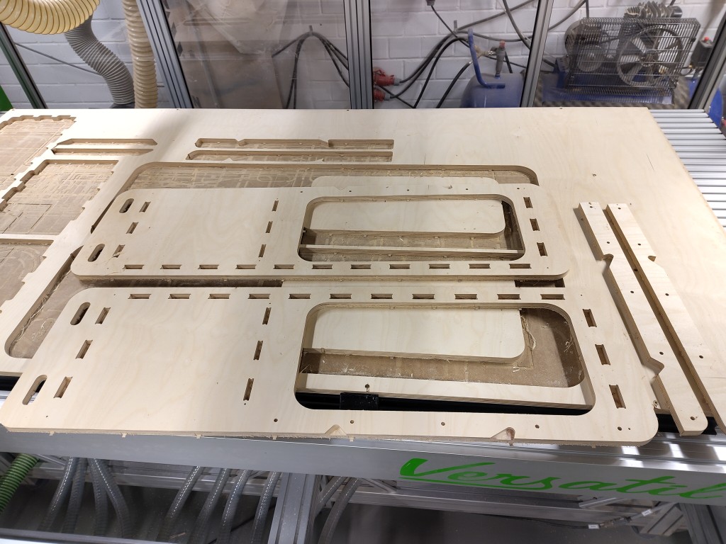
Operation 01
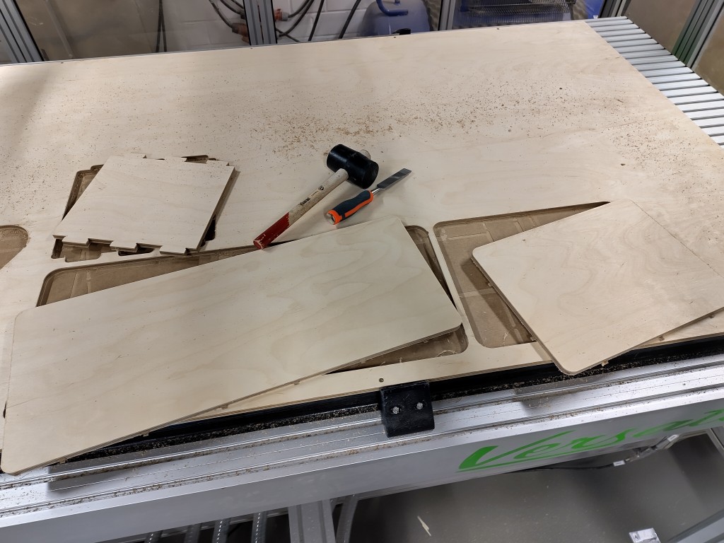
In the first step, I milled the base plate for the seat and backrest, as well as the center section, from 12 mm multiplex. This is the basic material available in Bottrop, although it wasn't absolutely necessary in many places. This milling job took about 20 minutes, but the geometries are and were comparatively simple. Here you can see the result, still screwed onto the sacrificial plate.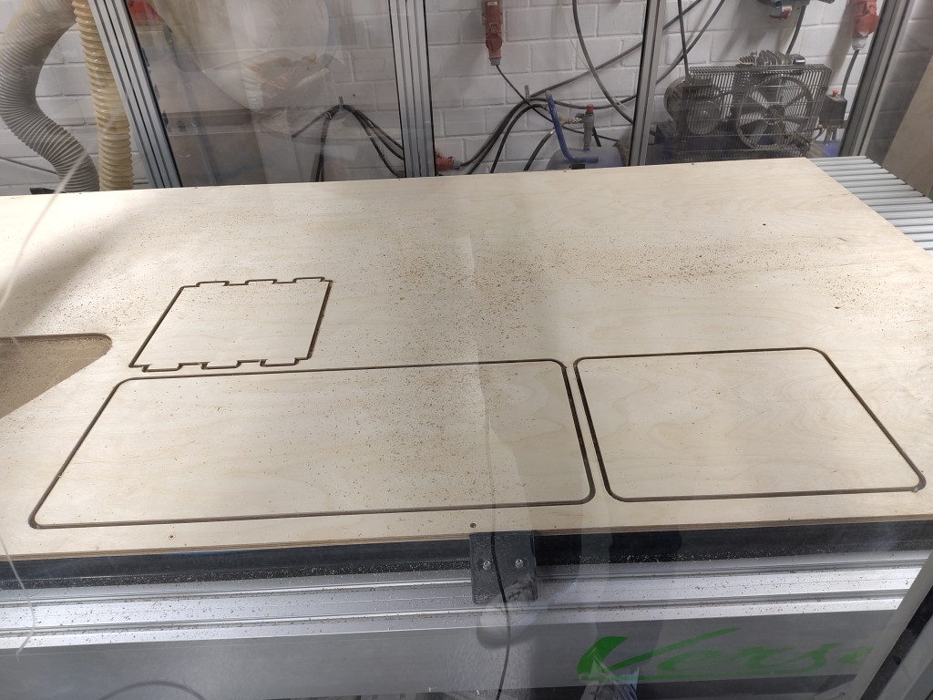
Operation 02
The milling process is similar, but the operations differ, as described above. Therefore, I will refrain from describing the two subsequent operations. A picture follows at the very bottom of each paragraph.All the experience gained so far in Bottrop during milling has not been able to say or estimate how long the jobs will take. Personally, I think that this should be a relatively central piece of information - especially as a guideline like our projects this week. All that is known so far is that Fusion360's forecast is wrong. To get closer to the truth, I stopped all tool changes and the associated operations for operations 02 and 03 and compared them with Fusion's forecasts. The result follows here in table form and is intended to be used to derive rough real times.
| No. | estimated time in Fusion360 | actual processing time | operation in Fusion360 | description |
|---|---|---|---|---|
| 1 | 0:01:30 | 0:03:54 | Drilling | tool diameter: 4 mm, drilling t-bones |
| 2 | 0:04:32 | 0:10:20 | 2D-Contour | tool diameter: 8 mm, scrubbing of contours |
| 3 | 0:00:48 | 0:06:03 | 2D-Contour | tool diameter: 4 mm, smoothing contours |
| 4 | 0:01:59 | 0:04:07 | 2D-Contour | tool diameter: 8 mm, scrubbing of contours |
| 5 | 0:00:55 | 0:02:47 | 2D-Contour | tool diameter: 6 mm, smoothing contours |
| 6 | 0:00:41 | 0:02:30 | Drilling | tool diameter: 4 mm, drilling t-bones |
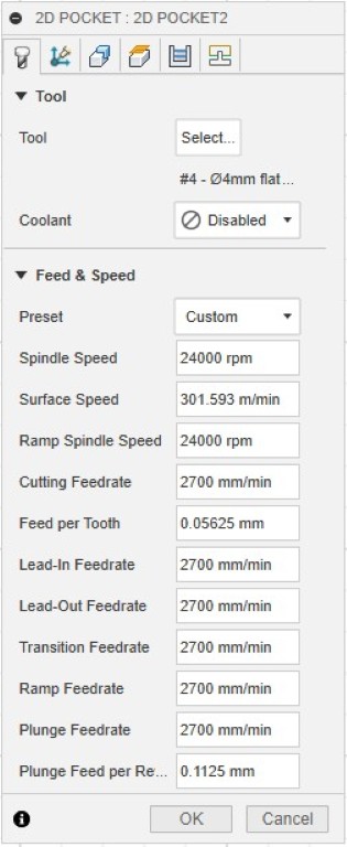
| 7 | 0:10:14 | 0:25:13 | 2D-Pocket | tool diameter: 4 mm, scrubbing pockets |
| 8 | 0:04:10 | 0:08:24 | 2D-Contour | tool diameter: 3 mm, smoothing contours |
| 9 | 0:03:36 | 0:07:59 | 2D-Contour | tool diameter: 8 mm, scrubbing contours |
| 10 | 0:06:39 | 0:09:53 | 2D-Contour | tool diameter: 3 mm, smoothing contour |
| 0:35:04 | 1:21:10 |
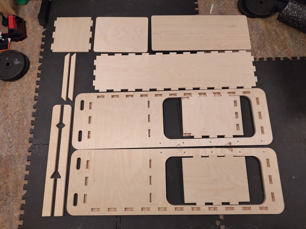
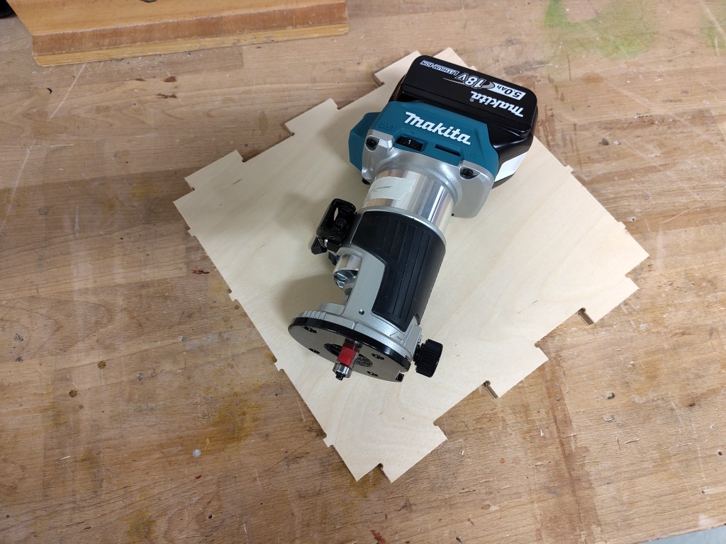
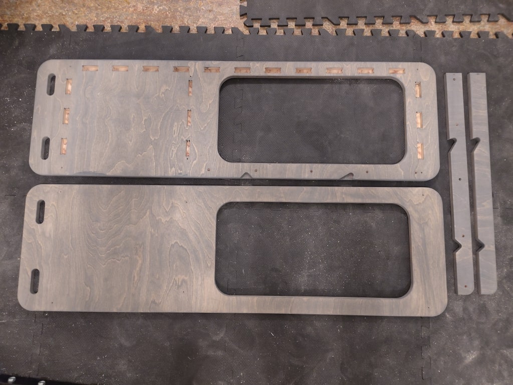
Now that the individual milling steps are known, I am providing a picture of the result. All parts were removed from the plate and reworked in the same way as the 12 mm parts.
Operation 03
For the third operation, I first removed the parts from the second one so that I could rework them while milling the other parts, keeping an eye on the current job. Important: With every tool change and thus every new operation, I checked very carefully to see if everything was actually running as planned or if any errors had slipped through. Fortunately, the latter was no longer the case thanks to the meticulous preparation.As in the previous operation, I stopped the times and listed them below.
| No. | estimated time in Fusion360 | actual processing time | operation in Fusion360 | description |
|---|---|---|---|---|
| 1 | 0:00:27 | 0:02:30 | Drilling | tool diameter: 4 mm, drilling t-bones |
| 2 | 0:12:44 | 0:49:15 | 2D-Pocket | tool diameter: 8 mm, scrubbing pockets |
| 3 | 0:04:01 | 0:38:38 | 2D-Pocket | tool diameter: 4 mm, scrubbing 8 mm holes |
| 4 | 0:02:37 | 0:18:26 | 2D-Contour | tool diameter: 4 mm, smoothing contours |
| 5 | 0:08:27 | 0:13:57 | 2D-Contour | tool diameter: 8 mm, scrubbing contours |
| 6 | 0:05:52 | 0:09:50 | 2D-Contour | tool diameter: 6 mm, smoothing contours |
| 7 | 0:07:52 | 0:10:03 | 2D-Contour | tool diameter: 8 mm, scrubbing contours |
| 8 | 0:05:21 | 0:07:20 | 2D-Contour | tool diameter: 6 mm, smoothing contours |
| 0:47:21 | 2:29:59 |
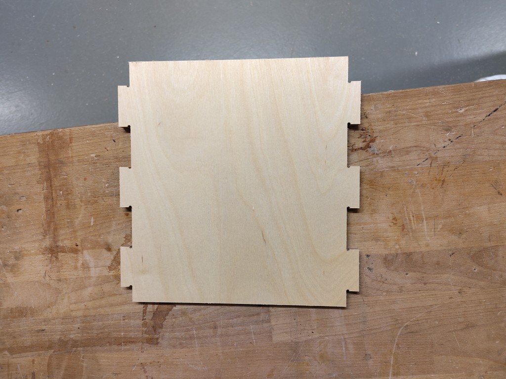
This is the result of me spending 2 hours and 30 minutes in front of the milling machine.
assembly
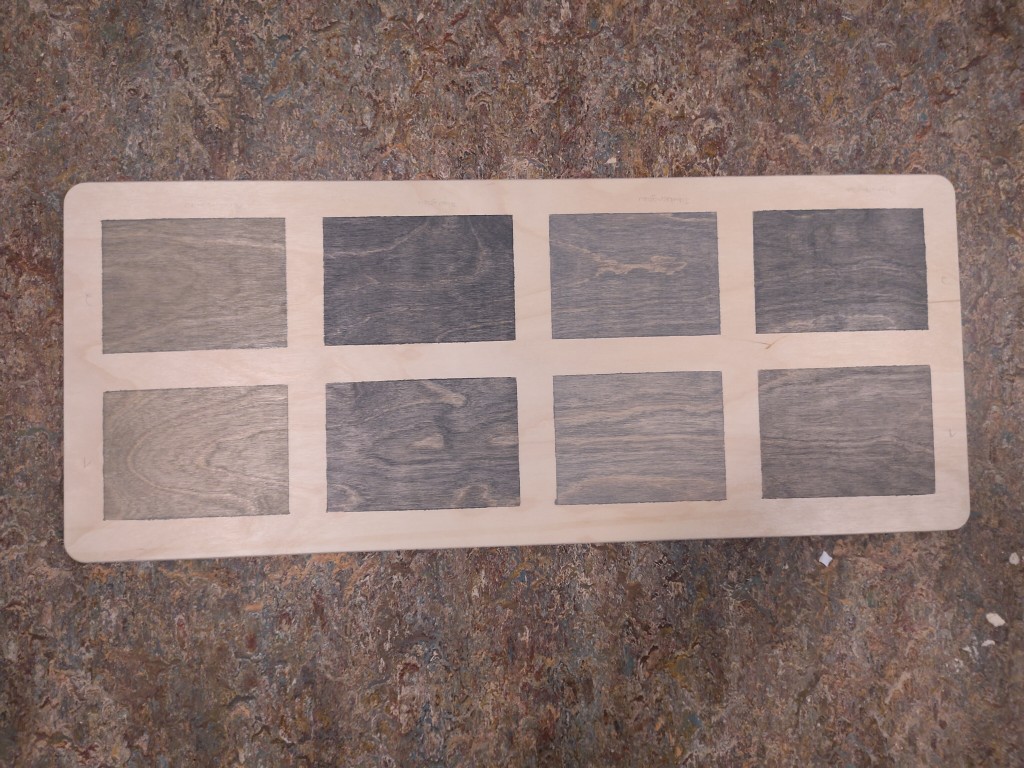
Before assembly, I still had to do some finishing because I didn't want to leave the wood untreated. Since my backrest will later be covered with foam and faux leather, offering a wonderfully large surface, I tested various pigmented wood oils, each of which I could get in 20-ml containers. To do this, I sanded the surface with a 220-grit sanding sponge, and later with 320-grit sanding sponge, in the direction of the grain, and taped it off as shown in the picture. In the top row, I applied the oil once and after 30 minutes, wiped off the excess oil with a nonwoven fabric. In the bottom row, I applied a second coat of oil instead. After consulting with various designers (thanks again!), I chose the color with the beautiful name "Asphaltgrau" perhaps a good first word for learning German. It works without any context.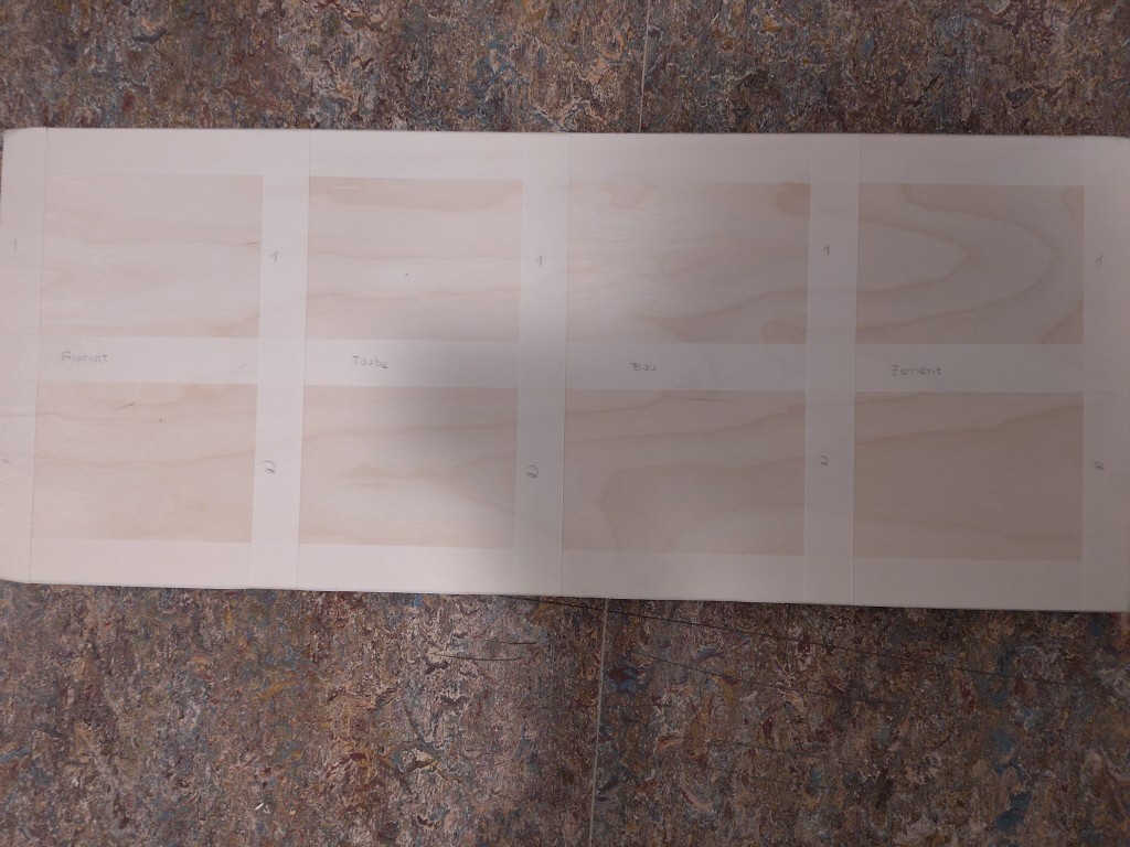
Before oiling the surfaces, I took a closer look at the wood and discovered that the 18 mm thick panels had unfortunately been sanded in two directions at the factory, meaning against the grain. The effect of sanding against the grain would be significantly enhanced by oiling, because the pigments are deposited primarily in these recesses. Accordingly, I sanded all surfaces in the direction of the grain until the cross-grain sanding disappeared. To illustrate this, here are two pictures: before and after sanding. I did the whole process with a disc sander, followed by finishing with the sanding sponges mentioned above.


I then finished my milled and sanded parts with hard wax oil. As you can see, I taped over all the plug-in parts to ensure my milled fit would still be correct. For a smoother surface finish, I then sanded the surfaces again very finely. Unfortunately, words can't describe how smooth the surface finish turned out.
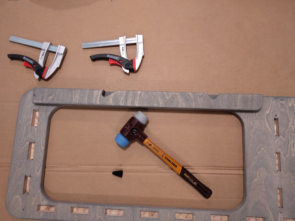
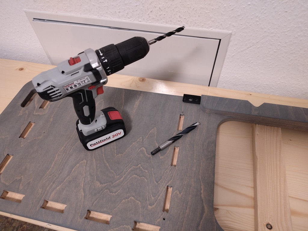
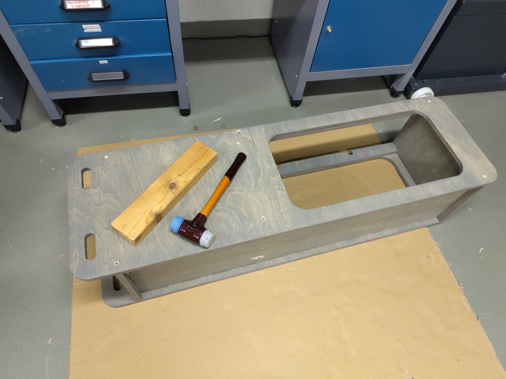
The next step was to take my two side pieces and reinforce them. For this, I used wooden dowels, reinforced with wood glue. So, at this point, a heartfelt farewell to this week's bonus points.
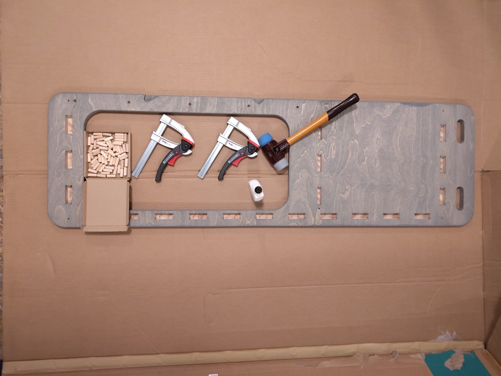
Because at this point I start using and needing additional materials for assembly, here is a short table of my materials.
| material | quantity |
|---|---|
| Wooden dowel 8x24 mm | 10 |
| sleeve nut plus matching screws in 35 mm length and washers | 4 |
| stainless steel screws, 4x40 mm | 6 |
| steel pipe, 16x2 mm, 272 mm length | 1 |
| round steel, diameter 12 mm, 270 mm length | 1 |
| square tube, steel, 20x1,5 mm, 599,5 mm length | 2 |
| square tube, steel, 20x1,5 mm, ~ 320 mm length | 2 |
| fitting screws, 8x50 mm - I recommend looking at the picture | 2 |
| washers for 8 mm screws, steel | 2 |
| washers for 6 mm screws, steel | 2 |
| washers for 8 mm screws, plastic | 2 |
| spring washers for 6 mm screws, steel | 2 |
| self-locking nuts for 6 mm screws | 2 |
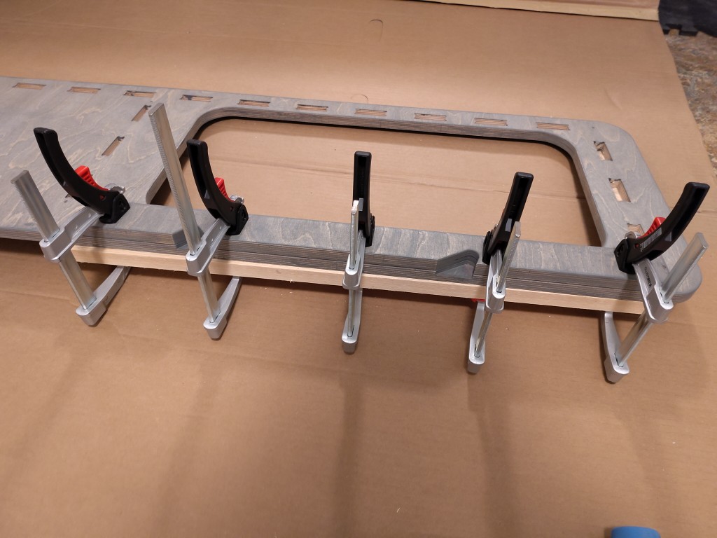
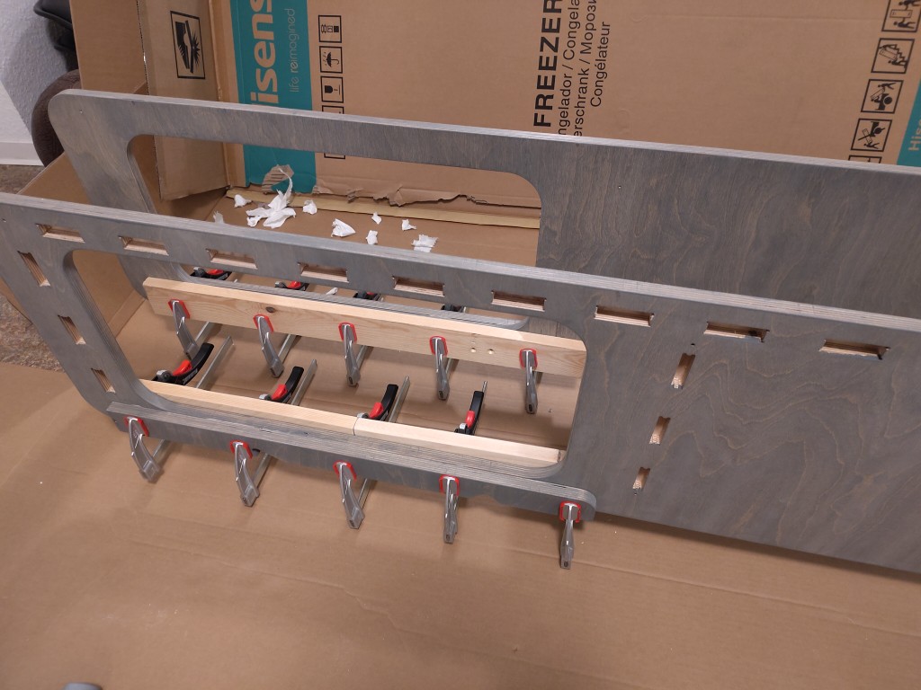
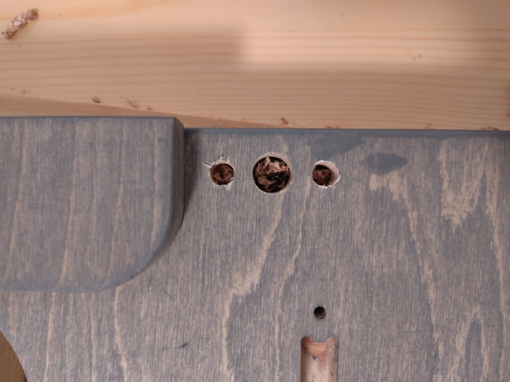
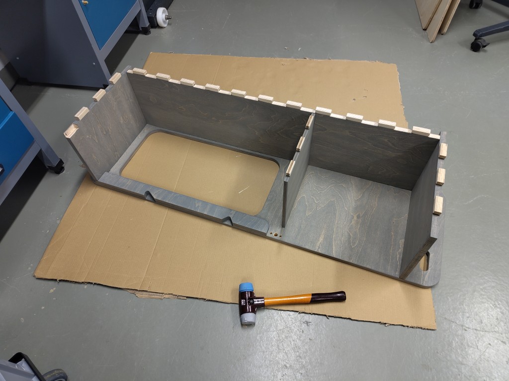
To do this, I took my pre-finished wooden pieces and combined them all. With the friendly assistance of our excellent colleague, Markus, I was able to put everything together bit by bit. Here, too, I used wood glue in some places, and I also used my pre-drilled screw holes on the side panels to additionally screw everything together so that it fits tightly. To ensure the screw heads are flush with the surface and the screw pressure is better, I countersunk the holes beforehand.
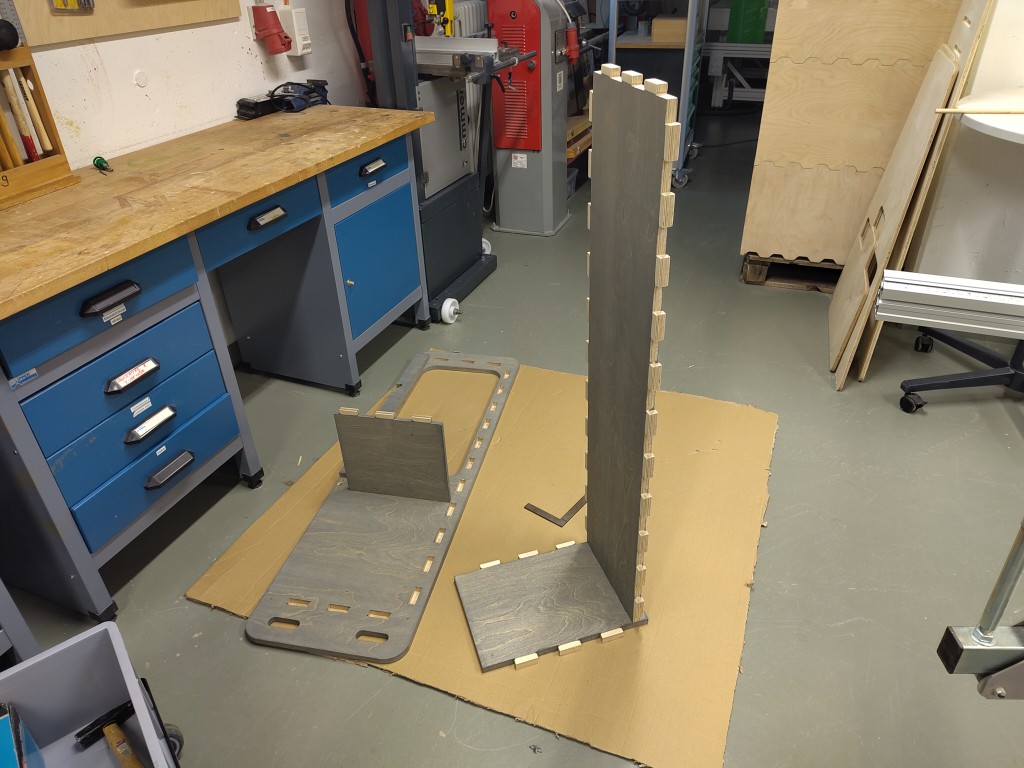
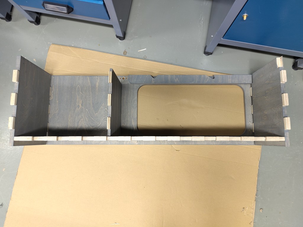
Little by little, I assembled my weight bench as shown in the slideshow.
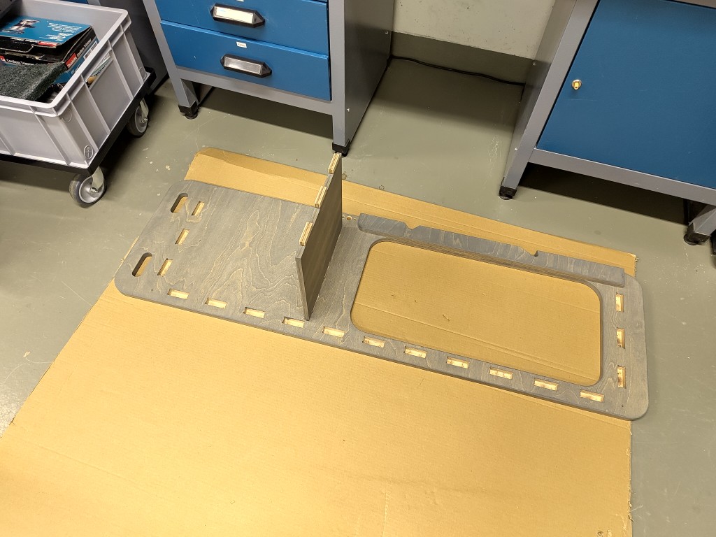
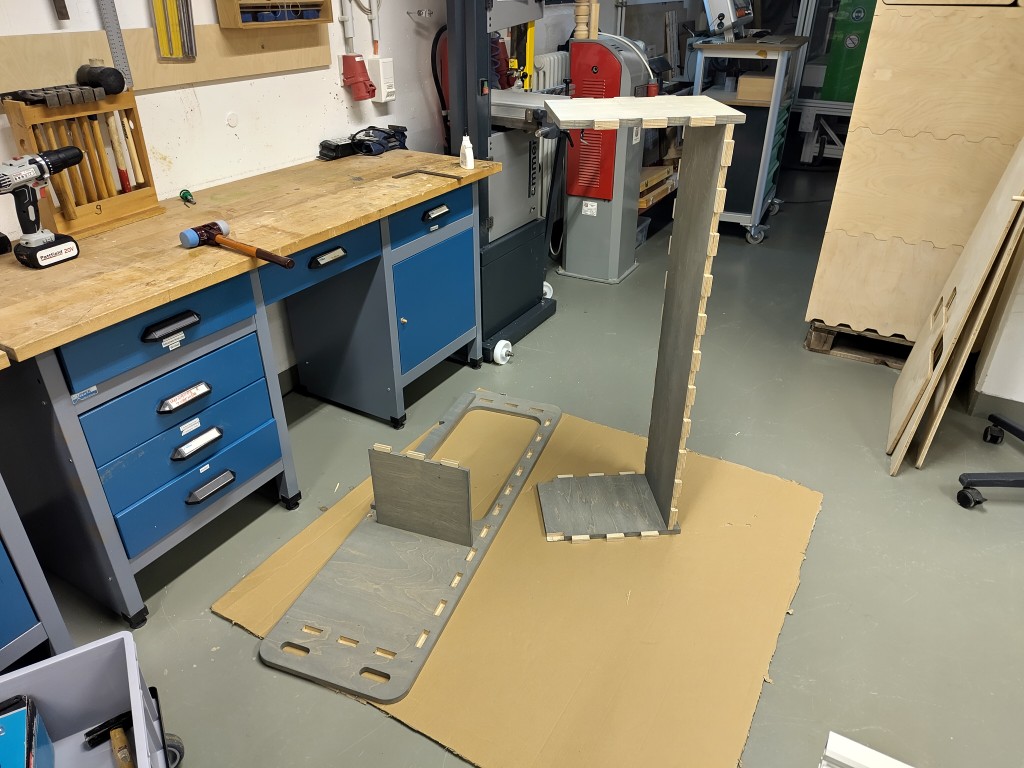
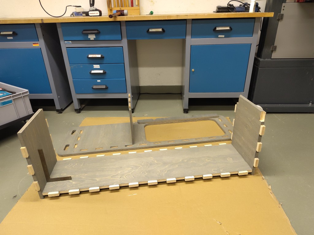
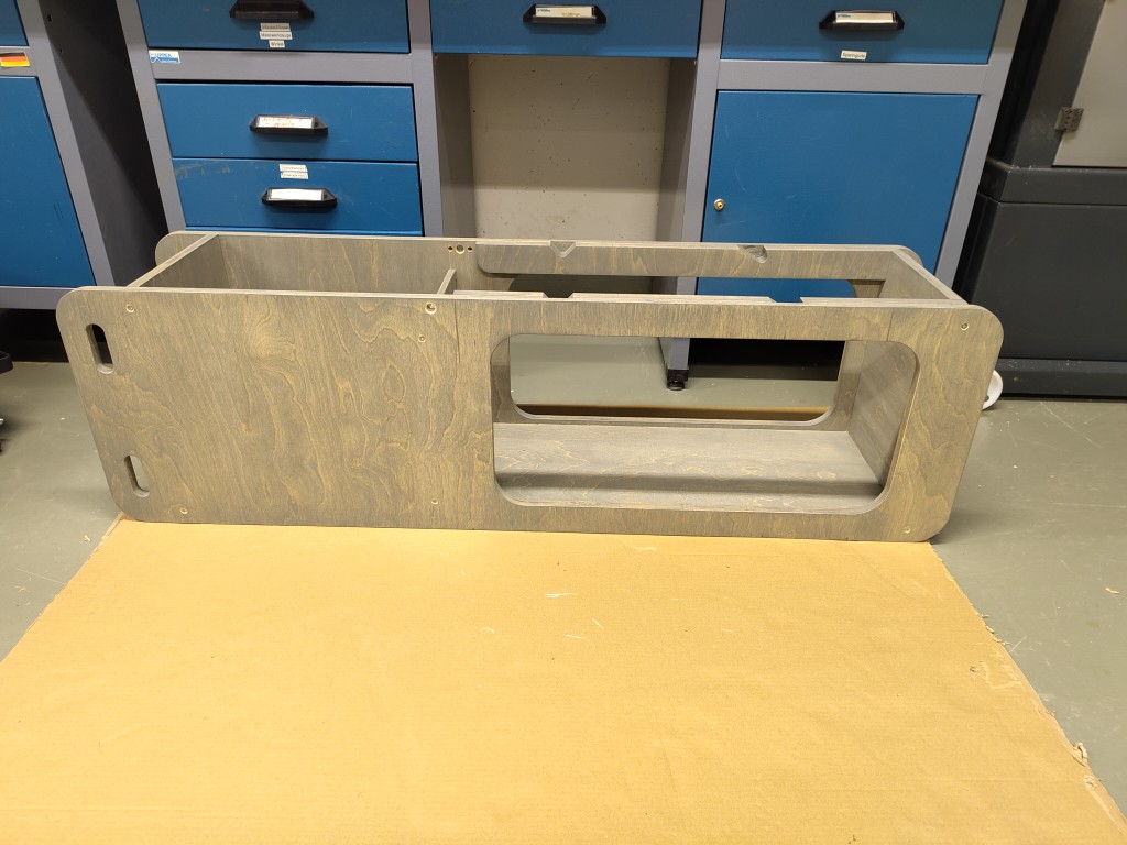
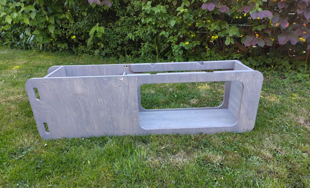
Here's my assembled weight bench in a natural habitat, still largely unpadded, and thus this week's hero shot. Further work will be done on it during Wildcard Week.