This week I have been looking into how print-in-place works and testing our 3D printers and their limitations. The specifications of the
printers do not differ that much, the specific engineering variant of the BambuLab printer offers expanded options in terms of printable
materials. Nevertheless, the benefit compared to the additional cost is rather questionable. When scanning, I was surprised that the partially
reflective material scanned quite well, even if the overall result of the scan did not satisfy me 100%.
3D scan an object
The first step in this assignment is to scan something. Since I've already had experience with this, I wanted to try something a little more
complex and decide on a theme for the week. So, against all reason, I decided to scan a bow tie. To do this, I used the Shining3D EinScan Pro
2X Plus with a turntable. There is a dedicated software called ExScan for this, which I was able to use.
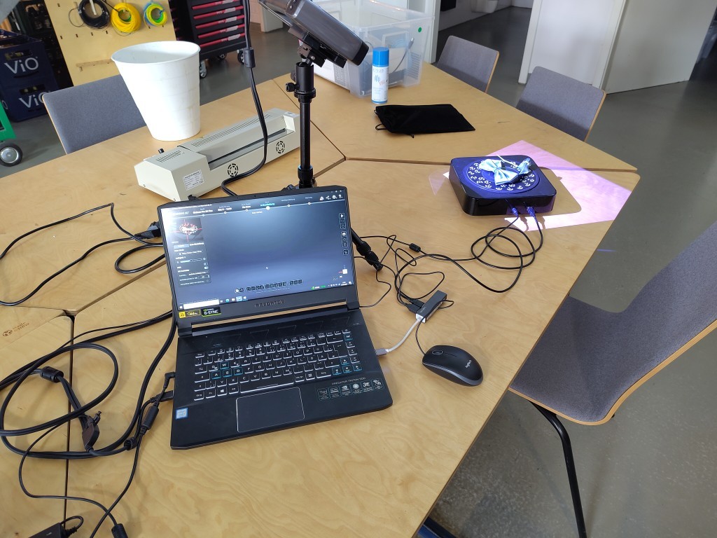
What you can see here is my hardware set-up. As you can see from the picture, I tried to leave some room for improvement in terms of cable management.
There are a few important points when setting up the system, such as the distance between the scanner and the object, which in this case needs to be
set so that the cross that the scanner projects is sharp on the part to be scanned.
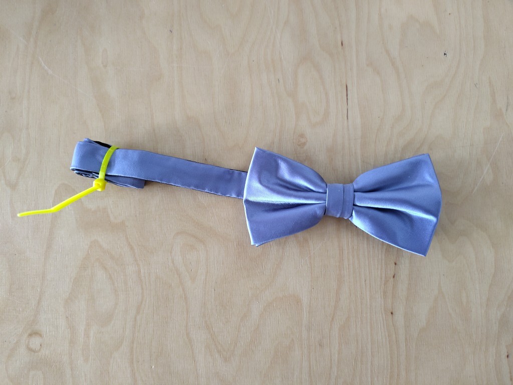
To ensure that the bow tie fits completely on the turntable and that no part dragging behind causes an unwanted rotation during scanning, which would
produce errors, I tied up the overhang.
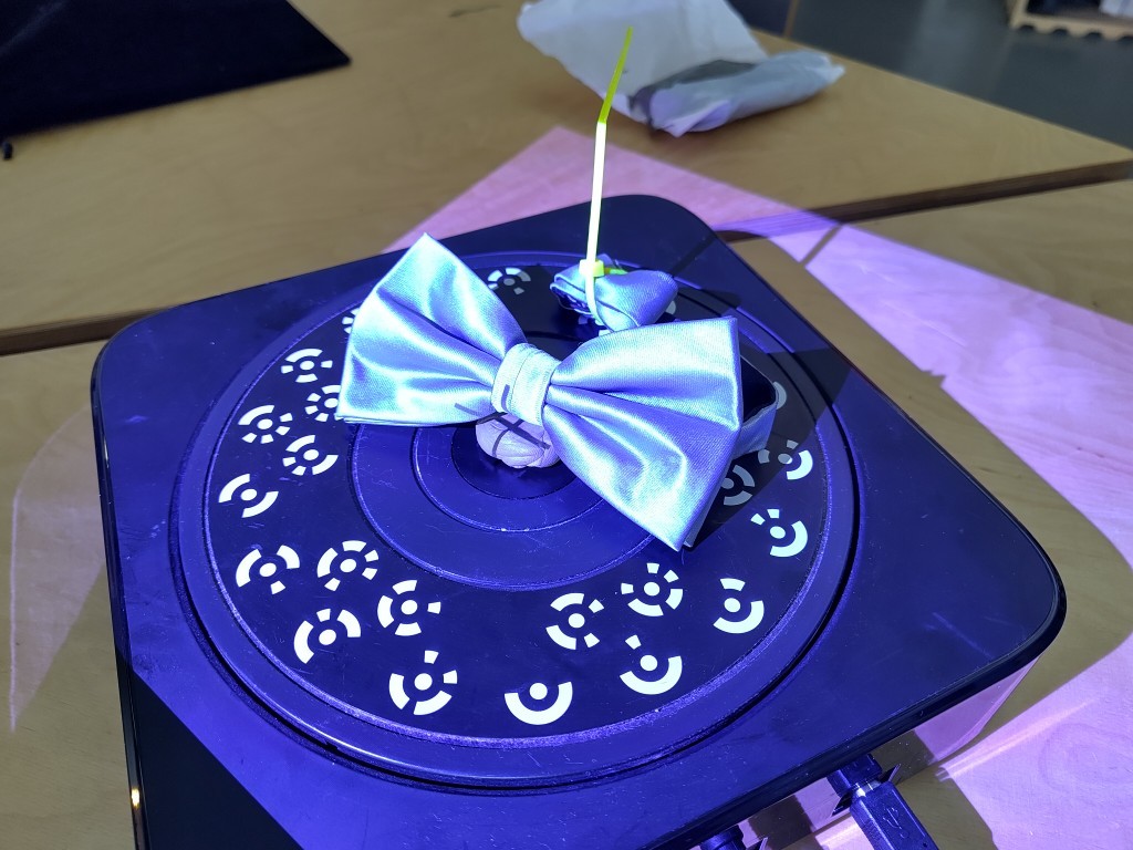
In this picture we no longer see the first scan. Here I am already taking the second perspective, for which the bow tie is slightly set up with clay.
Here you can see, as mentioned before, the projected cross, which is in focus on our object or in the center of the turntable.
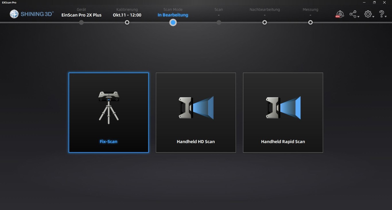
This brings us to the software and how to use it. First of all, we create a new project and use the fix scan.
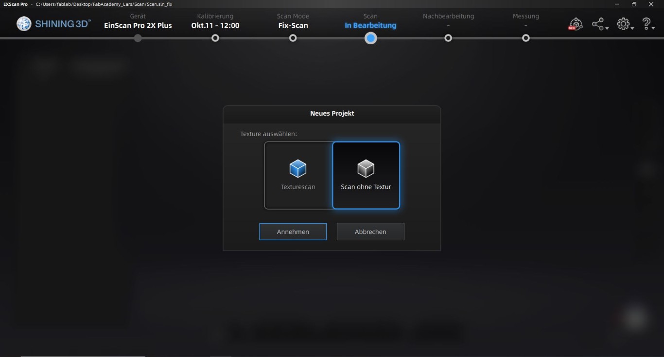
Next, we choose the scan without texture because we cannot detect the color of the object - extensions of the scanner make this possible.
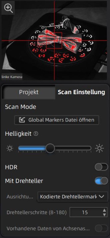
After that, we have created all the settings and are now in the program itself. If we first look at the left menu, we can see the points and surfaces
marked in red in the preview image at the top left that are clearly visible with the current settings for the scanner. This depends largely on the brightness
setting, which is called "Helligkeit" in the German software.
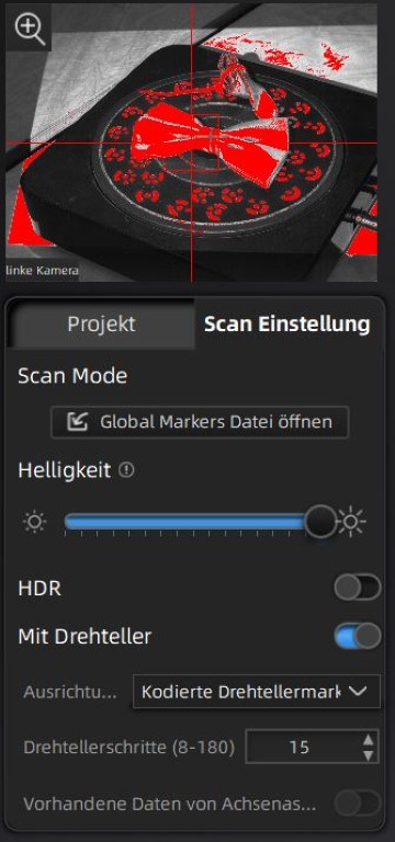
To show the effect of the brightness, I have set the brightness to maximum here. You can clearly see that areas that are clearly outside of our turntable are
now also detected. For scanning itself, the settings shown in the image above are almost optimal; it is enough that part of the surface of the part to be scanned
is highlighted in red.
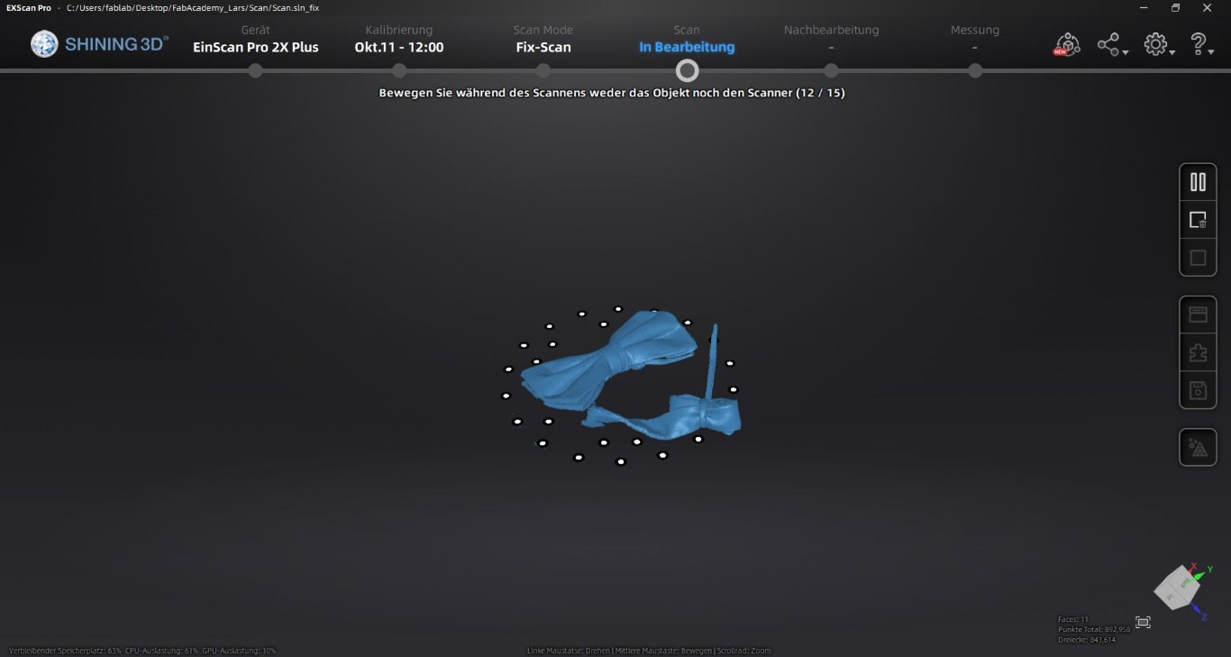
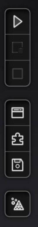
The button on the right, where the pause button is visible in the following image, is a play button that we can use to start the scan without a scan or post-processing
in progress. Here we see the first scan in which 12 of 15 turntable steps have been processed. We also see the turntable markers in black and white, which are needed
to locate the measuring points but are automatically calculated out of the scan.
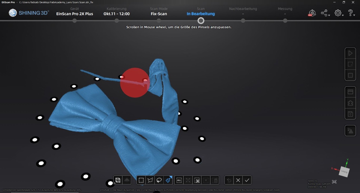
After completing all the steps on the turntable, we get a model in which we can edit or delete the individual data points. By pressing the Shift key, we get a red marker
that works like an eraser in other programs. We use this to mark all the data points that we do not want in our model. In my case, this is mainly the attachment that is on the bow tie.
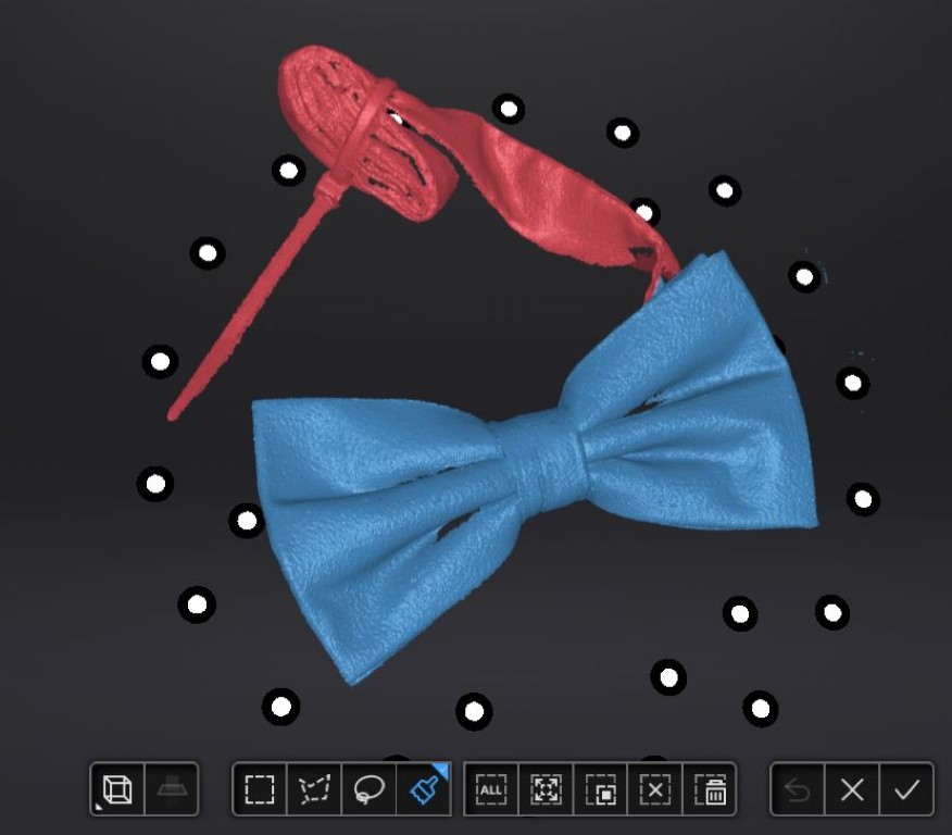
When deleting the data points, it is a good idea to keep playing with the perspective and rotate the object so that all the points to be deleted are easily accessible. In the next step,
the parts or points highlighted in red are deleted from our scan by clicking on the symbol with the trash can at the bottom right. We can then import our scan into our model using the
right-hand button, where the confirmation checkbox is located.
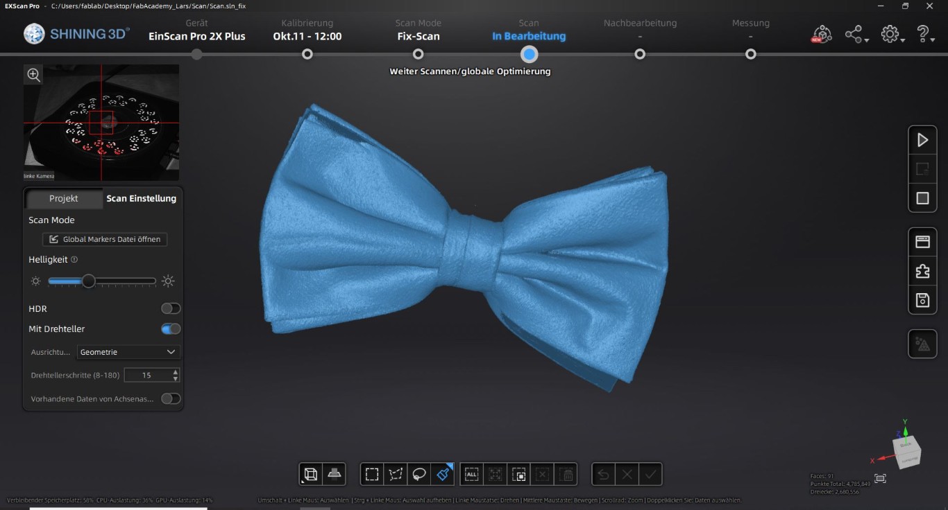
This completed the first scan run. For all subsequent scans, I no longer use the coded turntable markers as orientation, but instead select geometry as the orientation in the menu shown
above, which is located on the left. This means that the program aligns the next scan on our model when inserting it based on the geometries already recognized; continuing to work with the
coded turntable markers here has often led to errors for me in the past.
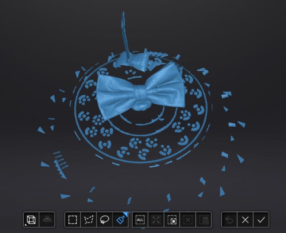
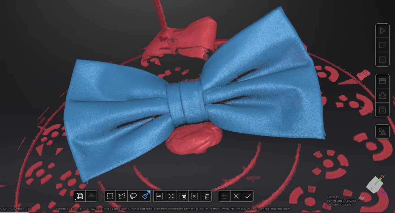
Here you can see the result of the next scan after all 15 steps. The turntable markers are still visible here, but we have to delete them manually as described above. You can also see the
clay that I used to present the bow tie to the scanner from a different perspective. We mark all of these parts in the same way as above.
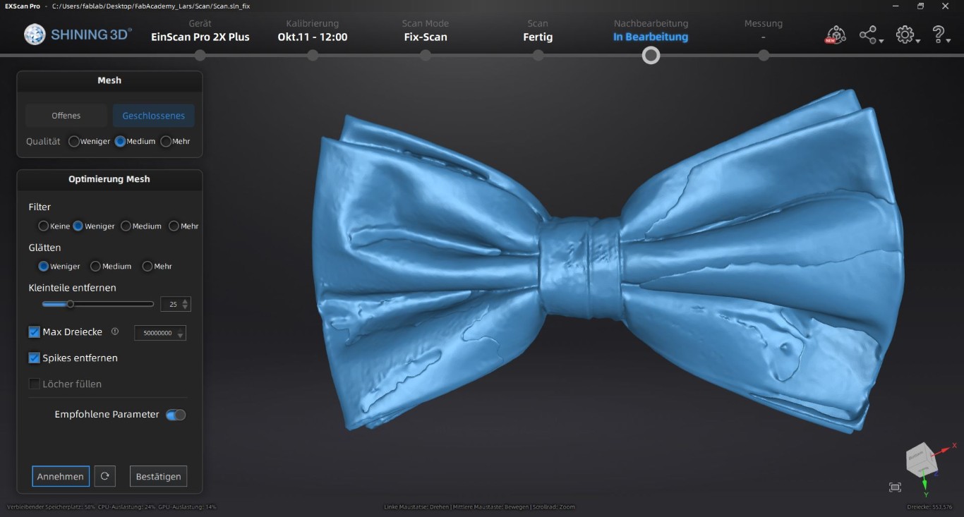
After deleting the points and confirming, the program combines the existing scans to create the following image, which is very close to the bow tie. Nevertheless, you can see parts that
are poorly depicted, in particular the entire back is missing. I therefore took further scans and combined them, but these are not shown in detail here.
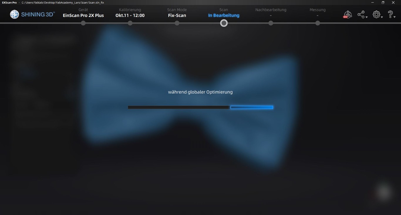
The next thing worth showing is the global optimization, where the program takes our scan points and creates a model from them. As soon as we are happy with our scan we can continue with it,
the option can be found under the start of the next scan. The whole process may take a while, so this is a good opportunity to have a Caipirinha if possible.
After the global optimization, we get the option to mesh the model in the bottom right bar, which is our next step to create a body from our scan.
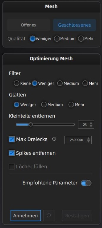
We are then taken to the options, which I will briefly translate below. From top to bottom, we first have the option of choosing between an open and a closed model. Here we choose a closed
mesh so that we can generate a body. Below that, in the "Mesh" block, we choose the quality, where we can choose from less, medium and more.
The next block is about optimizing the mesh. We first get the option to filter, where we can choose none, less, medium and more. Below that is the option to smooth, where we find the same options as above.
We use the slider to set which small parts of which size should be automatically removed from the model. As far as I understand, this is about free bodies that have no connection to our main element
and therefore do not add up to any total size. The option we click on specifies that we can set the maximum number of triangles from which the model is created. This is a very valuable setting for later
processing in Fusion360, for example, as too many triangles often cannot be processed. The second option clicked is for removing spikes and is shown in the recommended parameters. The fact that the
recommended parameters are active is shown below the line with the toggle box.
At the bottom left we can accept the settings as they are, which would trigger the creation of a 3D body that we can then export. However, it will take some time until this happens. At this point I would
like to remind you of the Caipirinha.
As you can see on the left, I have changed the settings again in the meantime. The result is the following model. Unfortunately, some inaccuracies arose when creating the body, but this could probably
have been corrected with more scans.
Because the file would be too big to upload here due to the number of triangles, here is a spectacular GIF of the 3D model rotating, contrary to all reason with the file size. I hope that these 1.12 MB
will be forgiven in view of this wonderfully pixelated representation. In this respect, the last reminder of the drinks is well placed.
Designing an object
This week we can finally declare my lack of creativity to be evergreen. I already have some experience with 3D printing and especially Fusion360,
so it would have been easy to quickly construct something that would not be possible or would be very difficult to produce subtractively. My idea
for this week was the print-in-place mechanism, which I wanted to look into. This means that with 3D printing, with the appropriate design, we are
able to create components that are movable. Under no circumstances can such mechanisms be manufactured subtractively. While looking for examples of
print-in-place applications, I came across a tie on printables.com. I personally find bow ties funnier and believe that they fit better with the
FabLab movement. So this week I set about creating a bow tie for the Fab25.
As an example of the shape and structure, I used the bow tie that I scanned above as a guide and redesigned it approximately in Fusion with the aim of
creating it as a print-in-place.
print in place
I have to admit that I don't find the design for print-in-place that easy. I looked at various tutorials and wasn't really happy with any of them.
Basically, it's about creating bodies that are connected to one another via a mechanism or joint that can move along an axis.
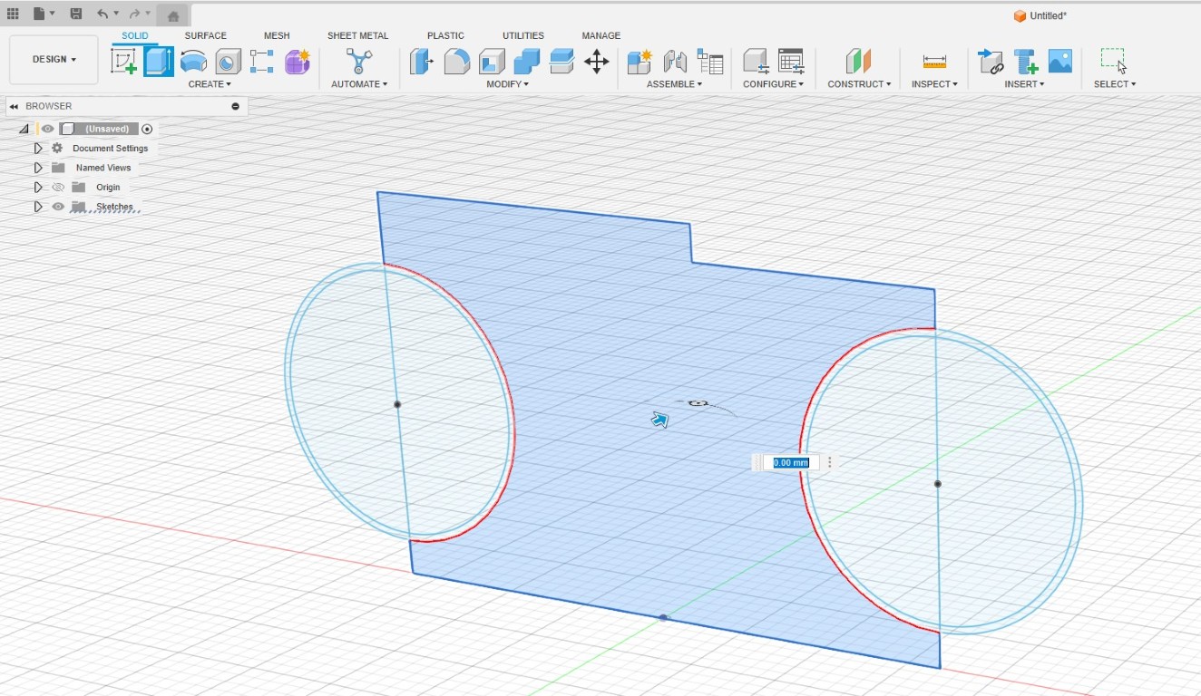
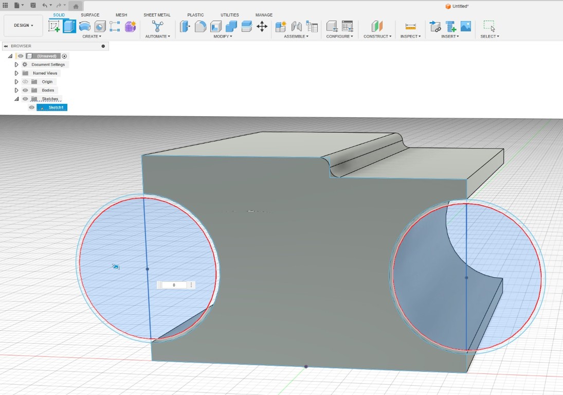
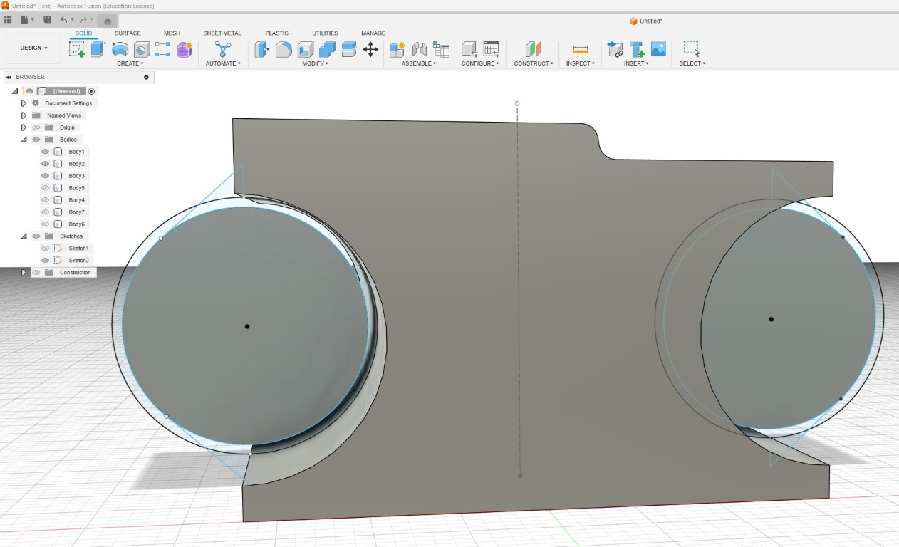
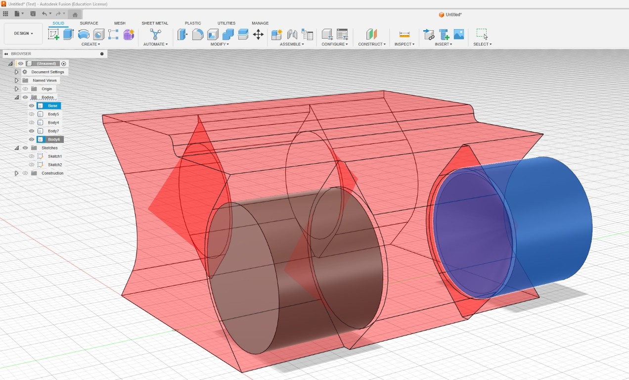
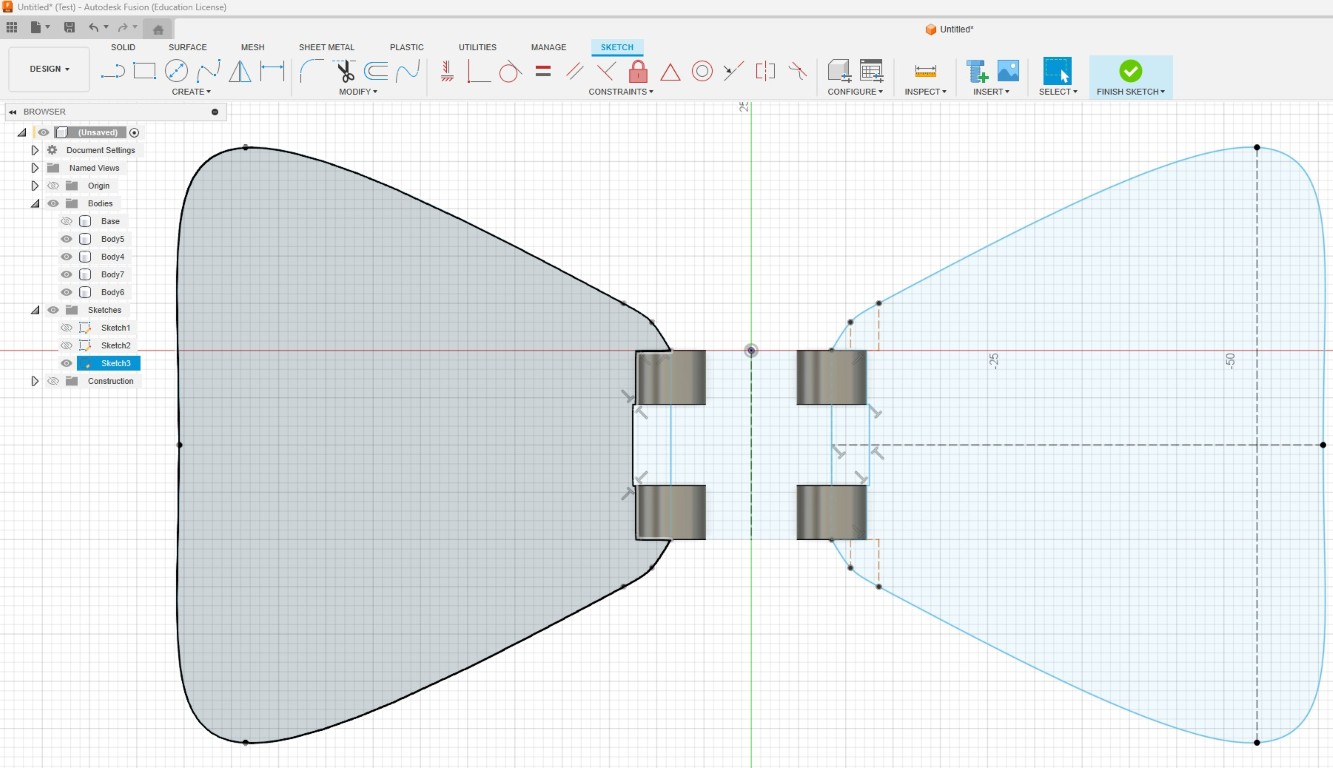
In the picture below you can see the connecting central body for my design and the two circular axes, each of which contains a circle with a radius
0.3 mm smaller, which will be important later. After looking at the various tutorials, the procedure of creating the axis of rotation from this side
and then pressing or pulling seemed to make the most sense to me.
Here you can see that I have already extruded the main body. Next, we need to extrude the inner circle to fit our two axes (left and right). In this
example, I am creating two print-in-place mechanisms at once, so keep in mind that you may only need to create this for your design.
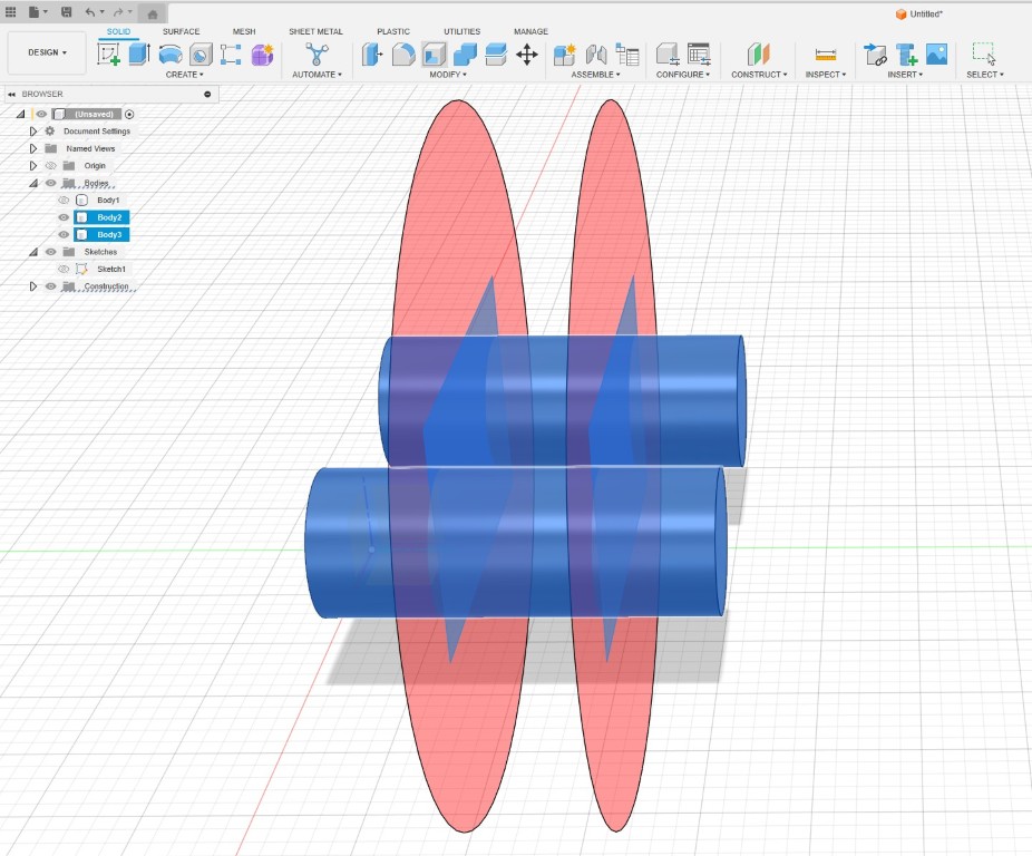
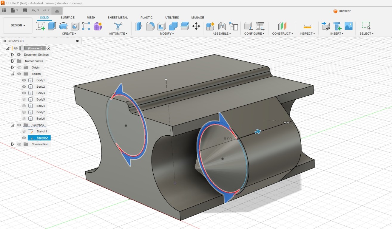
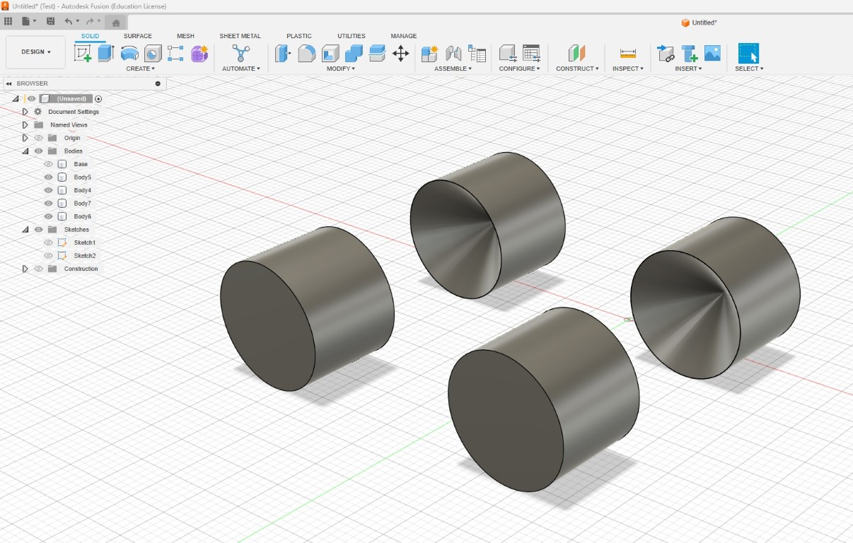
Then I created two planes so that I could divide or cut the rotation axes. In my case, I did it by making two cuts into three parts.
Here is the cutting operation. The distance from the outer sides is 6 mm each. The inner body is not symmetrical, it has a length of 8 mm.
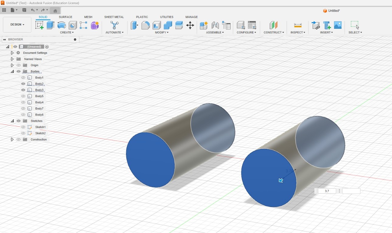
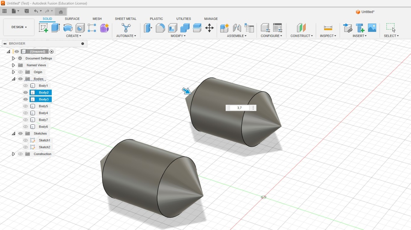
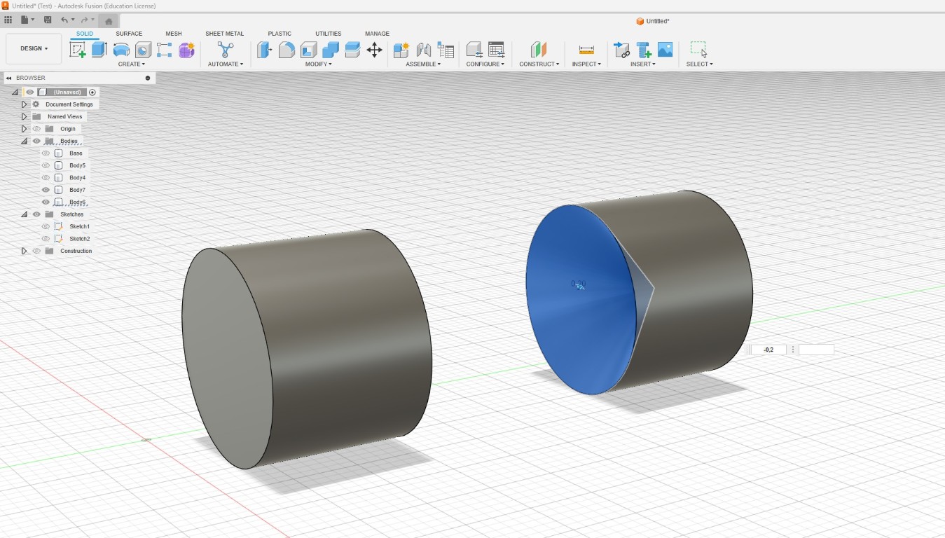
Then I extruded the inner body or part of the rotation axes around the radius (3.7 mm) in both directions. Then I created some space between each
of the three bodies and shortened the two outer bodies from the inside by 0.3 mm to create a gap. 0.3 mm is a good size for this on modern printers.
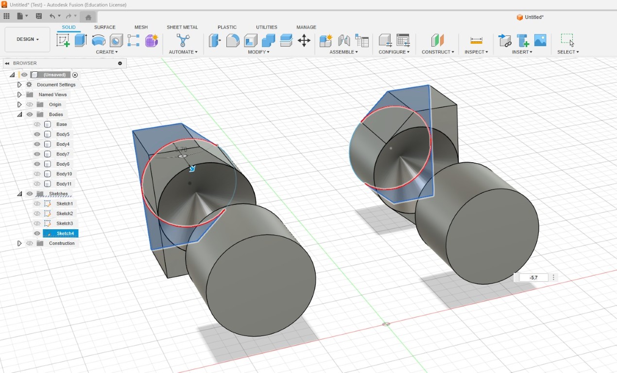
I then chamfered both ends to the length of the extrusion, which creates the pointed ends on both sides. They are the trick to connecting the components together.
The chamfer has a slope of 45° and can therefore still be printed easily using the layered process. At the same time, this geometry extends so far into the second
part of the design with the matching mounts in the counterpart that it no longer falls out when printed later.
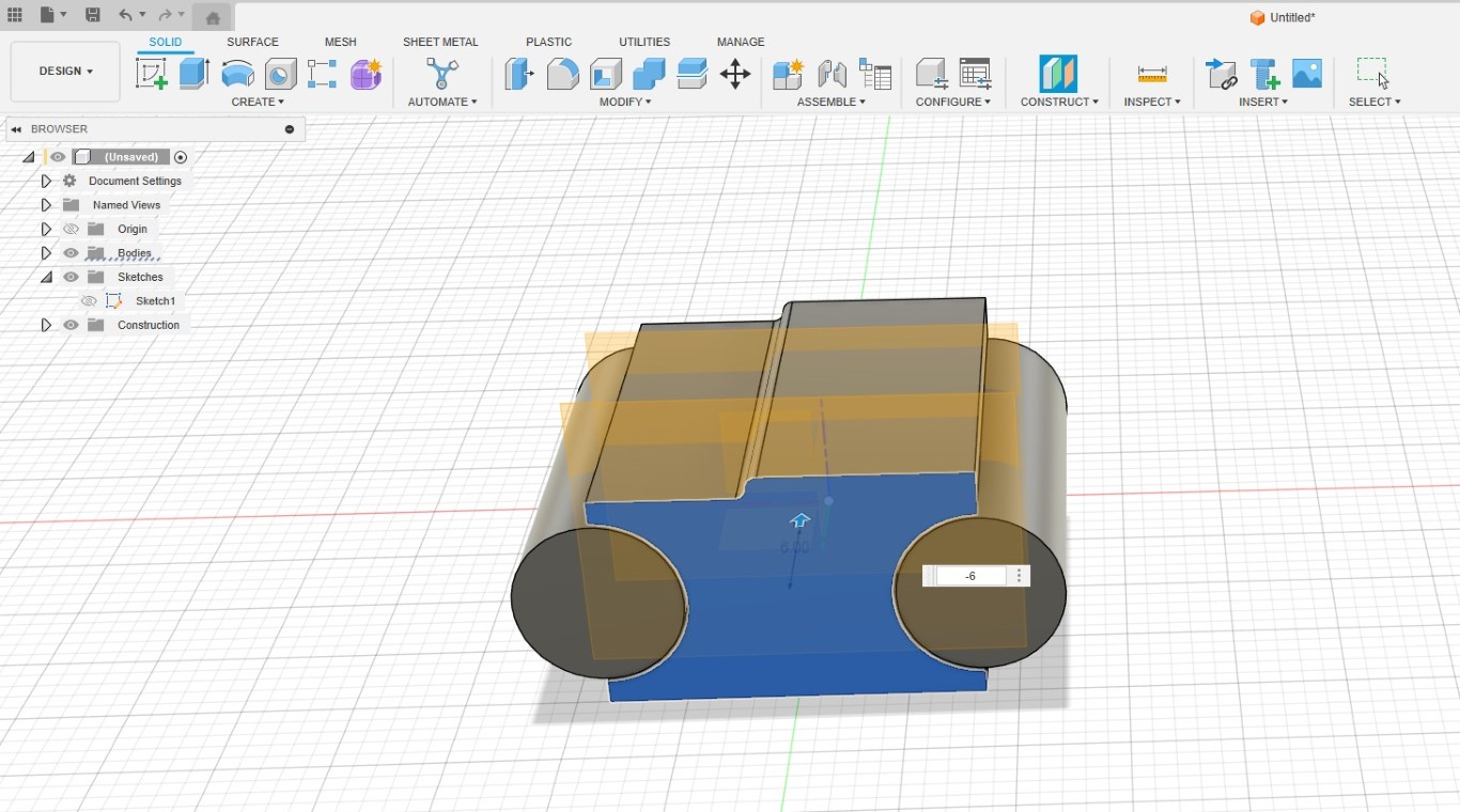
Next, I edited the existing sketch so that I could connect the middle part to the base body.
This is the corresponding extrusion operation. I haven't connected the bodies yet.
In the next step, it is important to create room for movement in order to benefit from the movable mechanism later. In a later operation, which unfortunately
is not illustrated, I increased the freedom of movement by increasing the cut-out angle. The middle part with both pointed cones will be connected to the middle
body at the end. The smaller bodies along the axis in front and behind will later be connected to the wings of the bow tie.
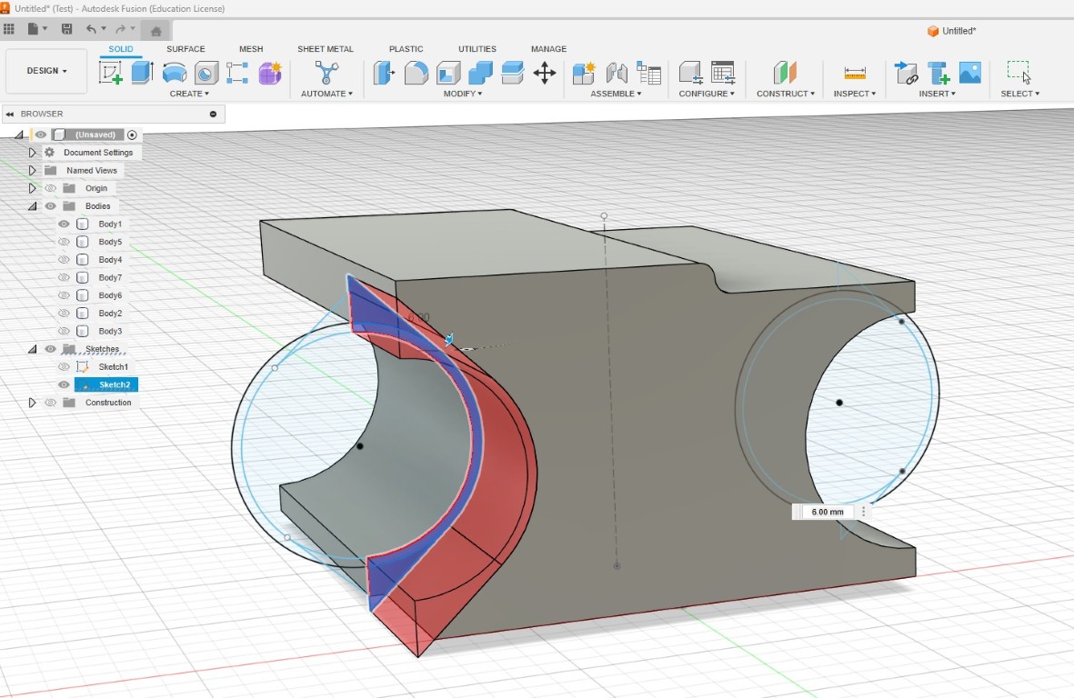
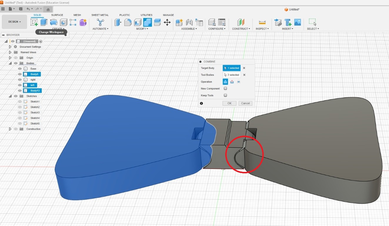
Then I connected the middle body to the base and cut it out of the two outer joint parts so that the bevel could fit there.
Because this operation would have created a flush cut that we would not have been able to remove after printing or that would have caused a lot of friction, I
pressed the surfaces further in.
This is what the result looks like so far.
Now it's time to work on the attachment points on the two joint parts that will later be connected to the wings of the bow tie. I made sketches for each of these
and extruded them. Here, too, I later adjusted the angle. I will point out the change in other pictures where appropriate.
Here is a cross-section of the print-in-place joint or component as a video, where you can see the principle again clearly.
designing the bow tie
Using a few rough measuring points from the original bow tie, I created a rough shape using splines and then extruded and connected it.
Circled in red you can see the rework I did on the angle for the print-in-place. It's not much, but you might notice the change.
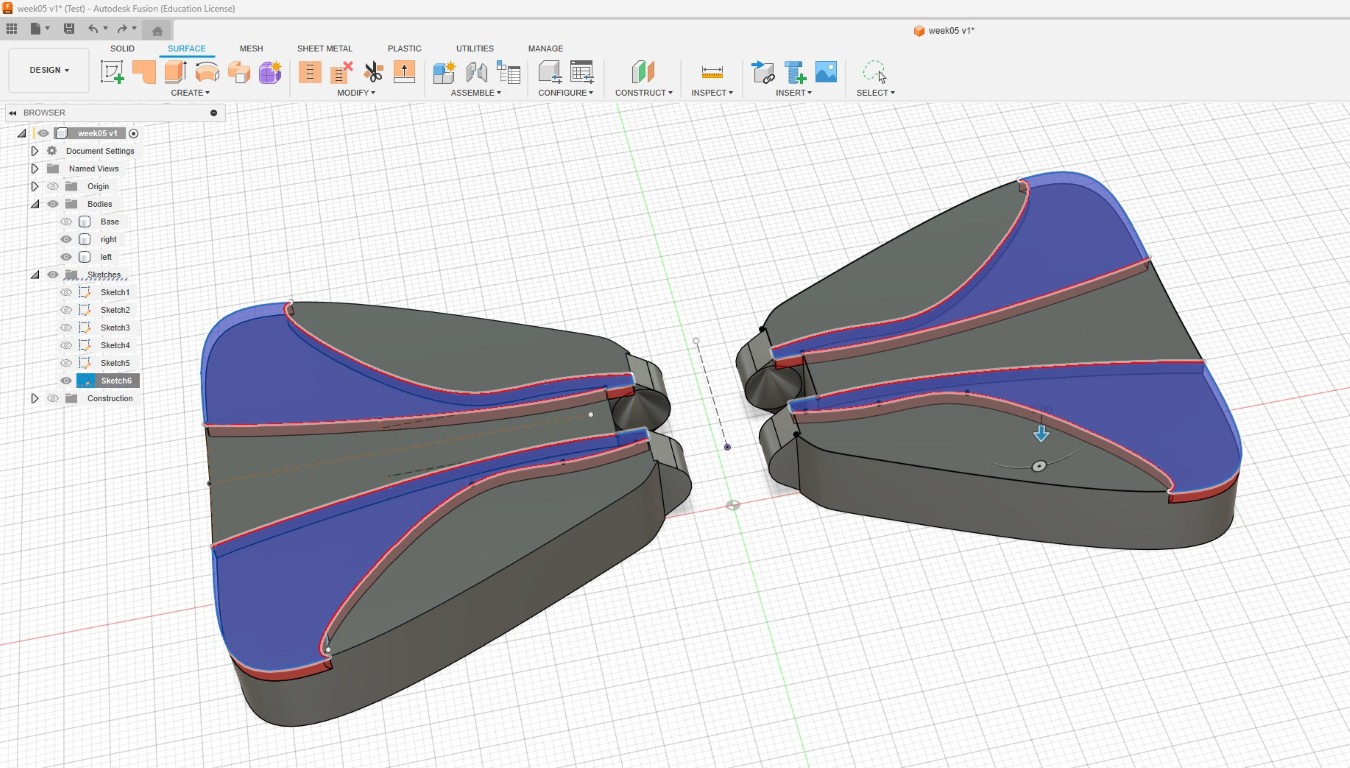
Also based on some rough measurements, I tried to recreate the waves in the fabric to get rid of the flat surface. For this, I also worked with splines,
which I later mirrored onto the other wing of the bow tie and cut out on both pieces.
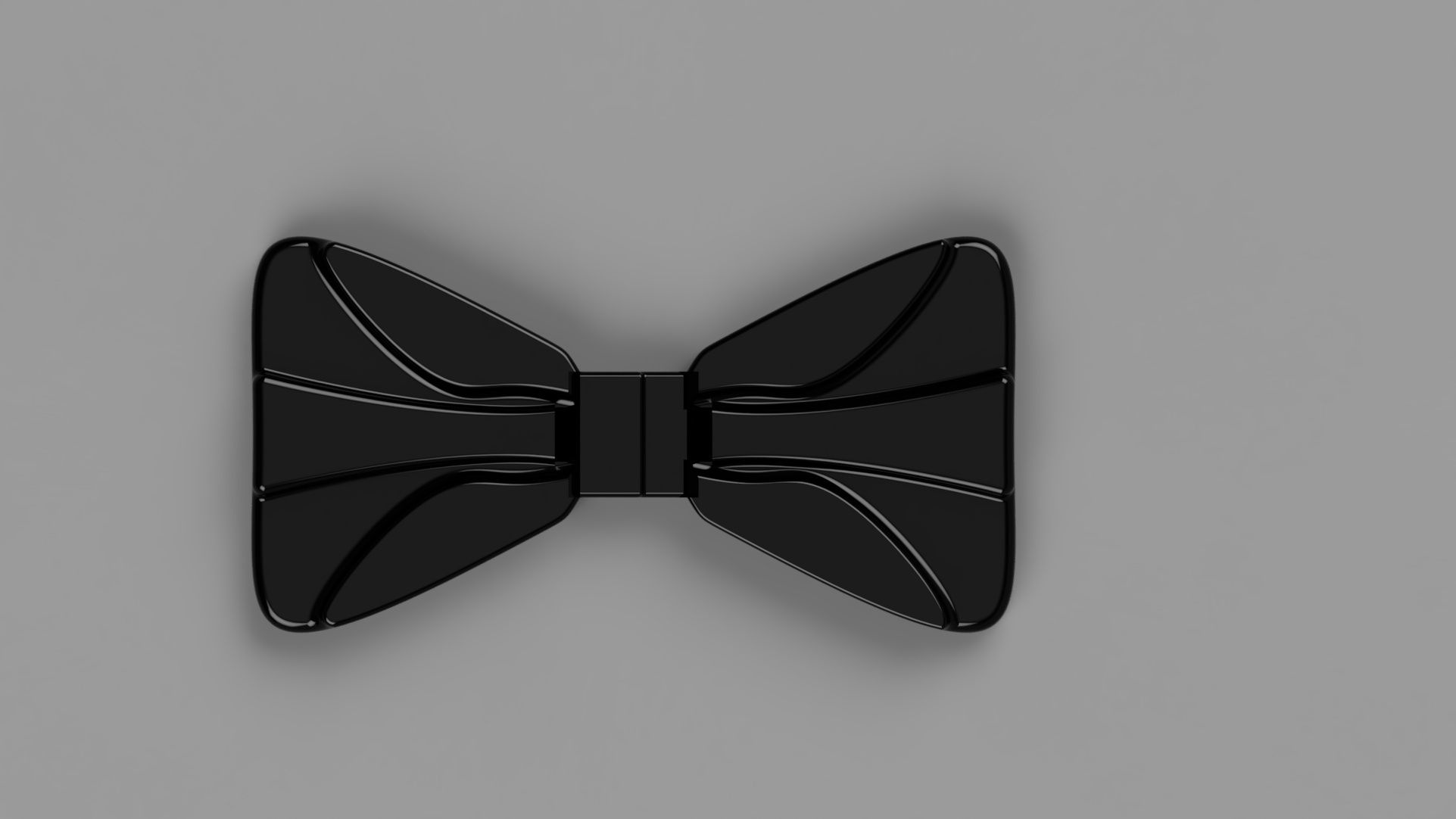
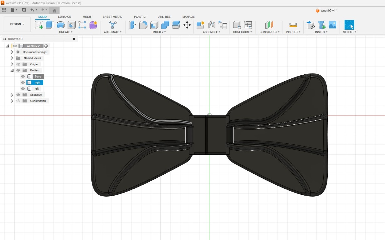
Finally, I rounded off all edges and chose black plastic for the representation.
To keep in practice, I quickly rendered the design in Fusion360 and this is the result.
Let’s see what the bow tie will look like printed.
3D printing
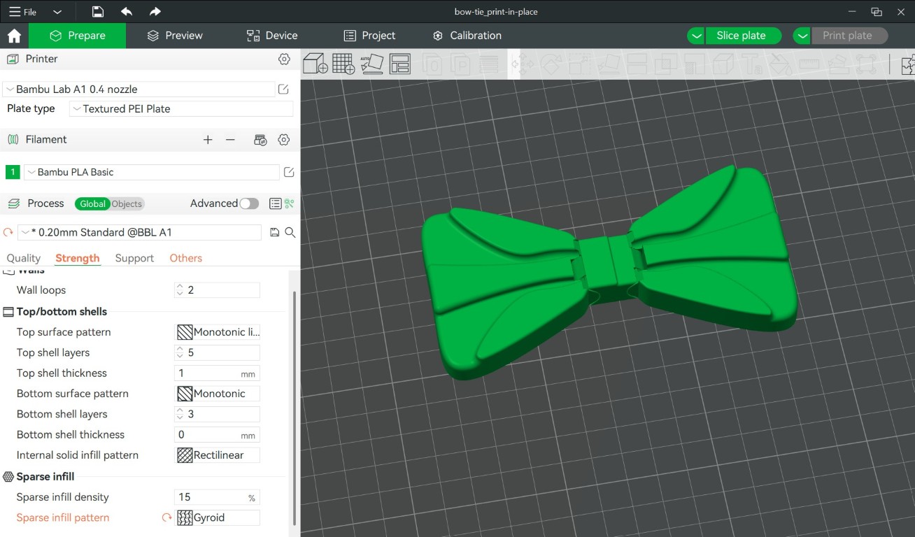
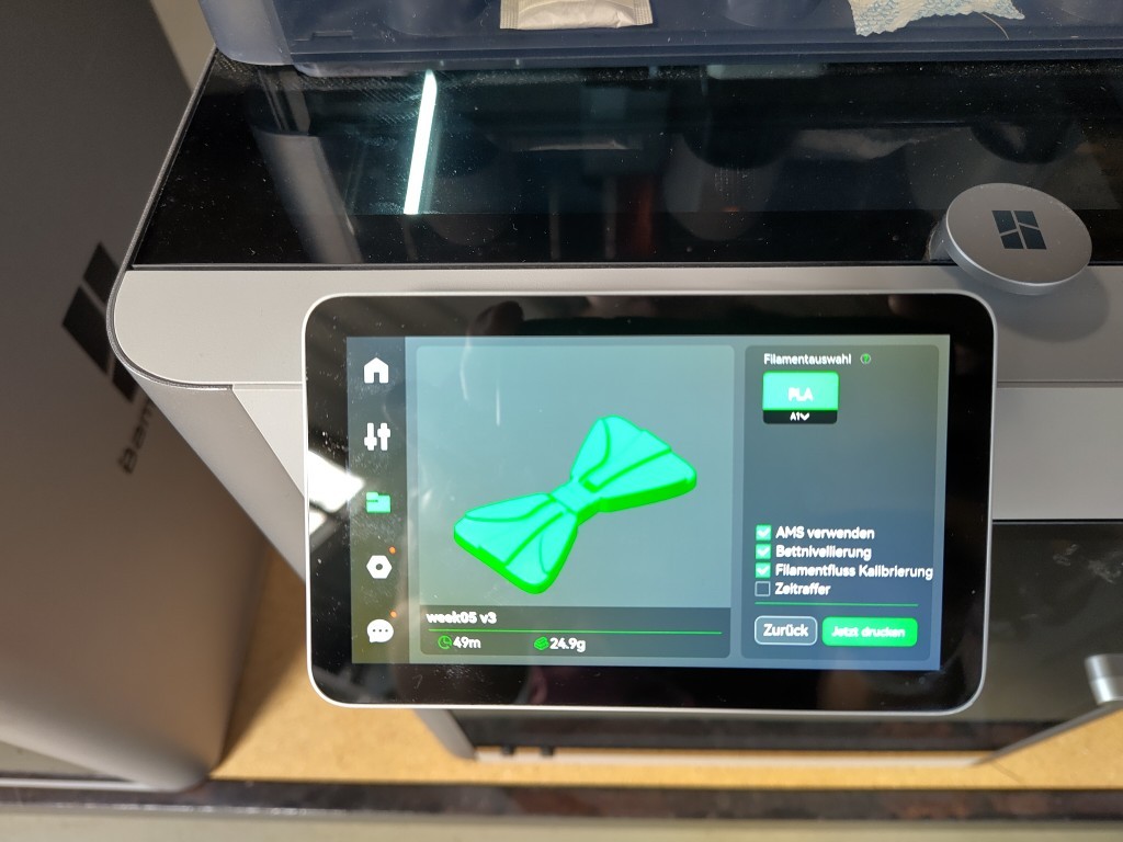
Because I use a BambuLab printer, I also use the slicer offered by BambuLab to create the G-code from the .3mf file that the printer works with.
This is what the software looks like when opened after you have inserted your component, in my case via drag and drop.
The only two changes I made here compared to the default settings were to change the orange highlighted Sparse infill pattern to Gyroid and to add two
skirt loops under Others.
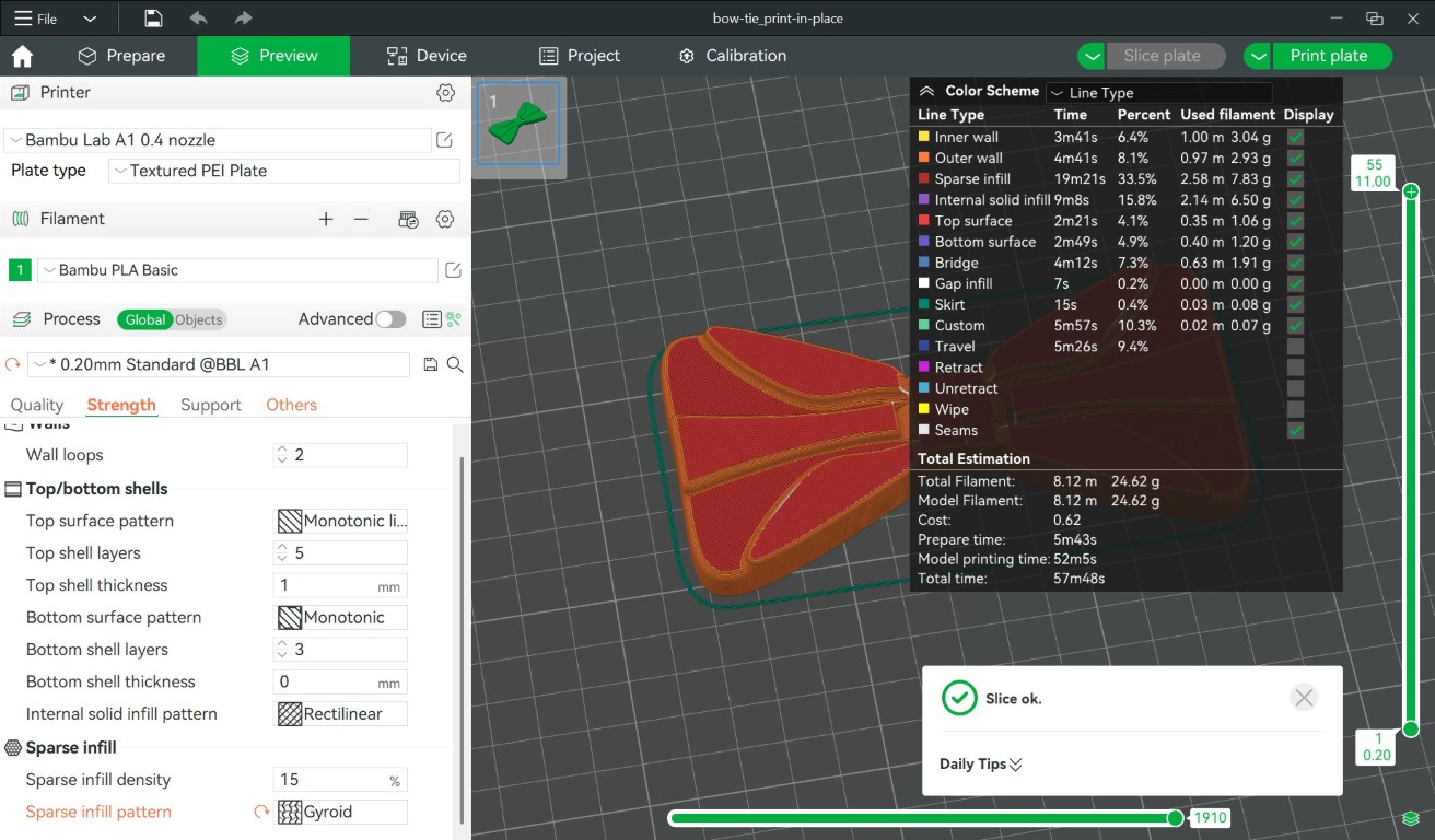
Then I moved on to the slice plate, in dark green around the actual print you can see the two skirt loops. This is where the printer gets rid of any
possible contamination or overextrusions so that the intended print itself is a little cleaner if something goes wrong.
We have already cut the design of the print-in-place in Fusion in the front view. Here is another short video in which you can see the whole thing
layer by layer from the printer's perspective. Such a mechanism cannot be produced subtractively.
After this short demo, we will continue by opening the drop-down menu in the top right menu instead of the "print plate" and then switching to
"Export plate sliced file" and selecting this. I do this because I am not or was not connected to the printer via the network, but rather I am
loading the file via a MicroSD card.
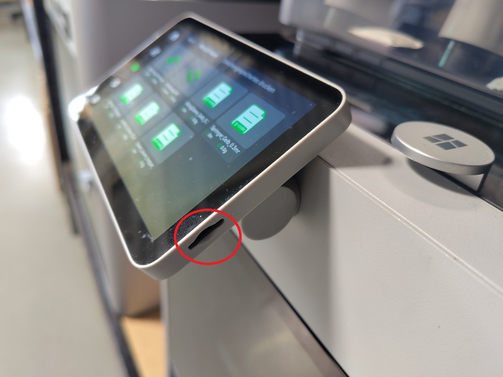
The sliced file can then be saved to the MicroSD card and then inserted into the printer slot.
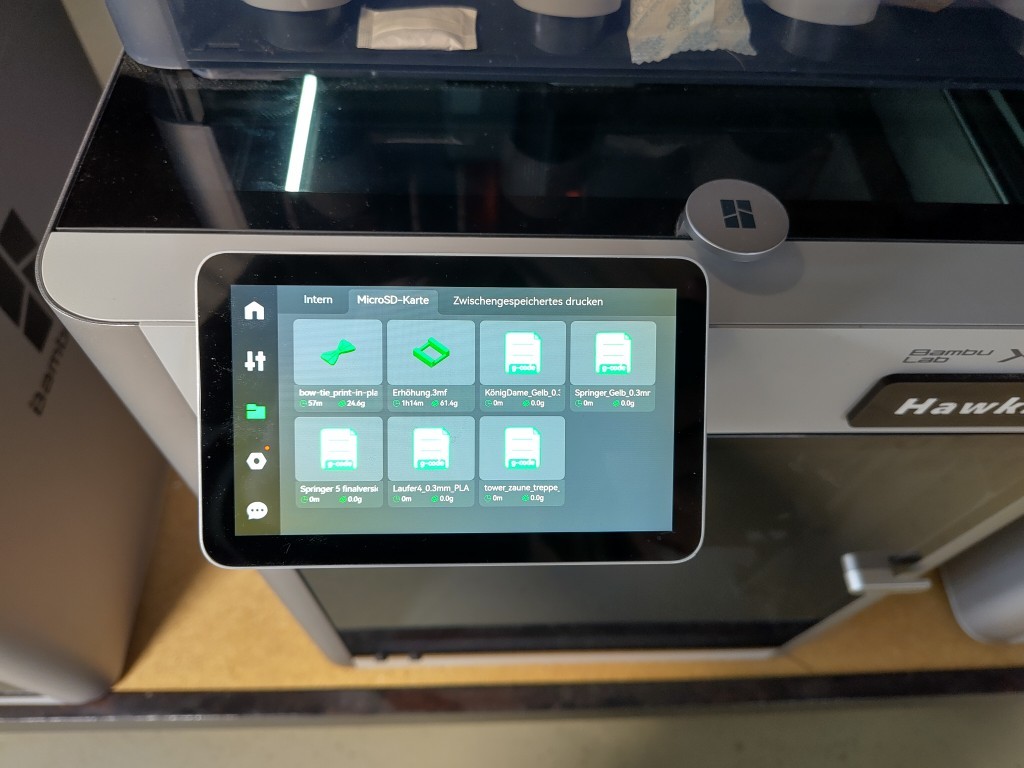
In the file explorer of the Bambu Lab printer you can now search for the file on the SD card that you want to print.
From here on, the path is extremely simple, unless you do it like I do. I always think it's great to translate proverbs. In Germany, we like to
say that what you don't have in your head is in your legs. In my case, that meant that I had selected the wrong printer in the top left of the
slicer software. So I had to slice the file again and put it on the MicroSD card. This also explains how the print time between the top image
and the image below miraculously shortens by 8 minutes. With the button at the bottom right, which translates as "print now", we can finish it
here and now.
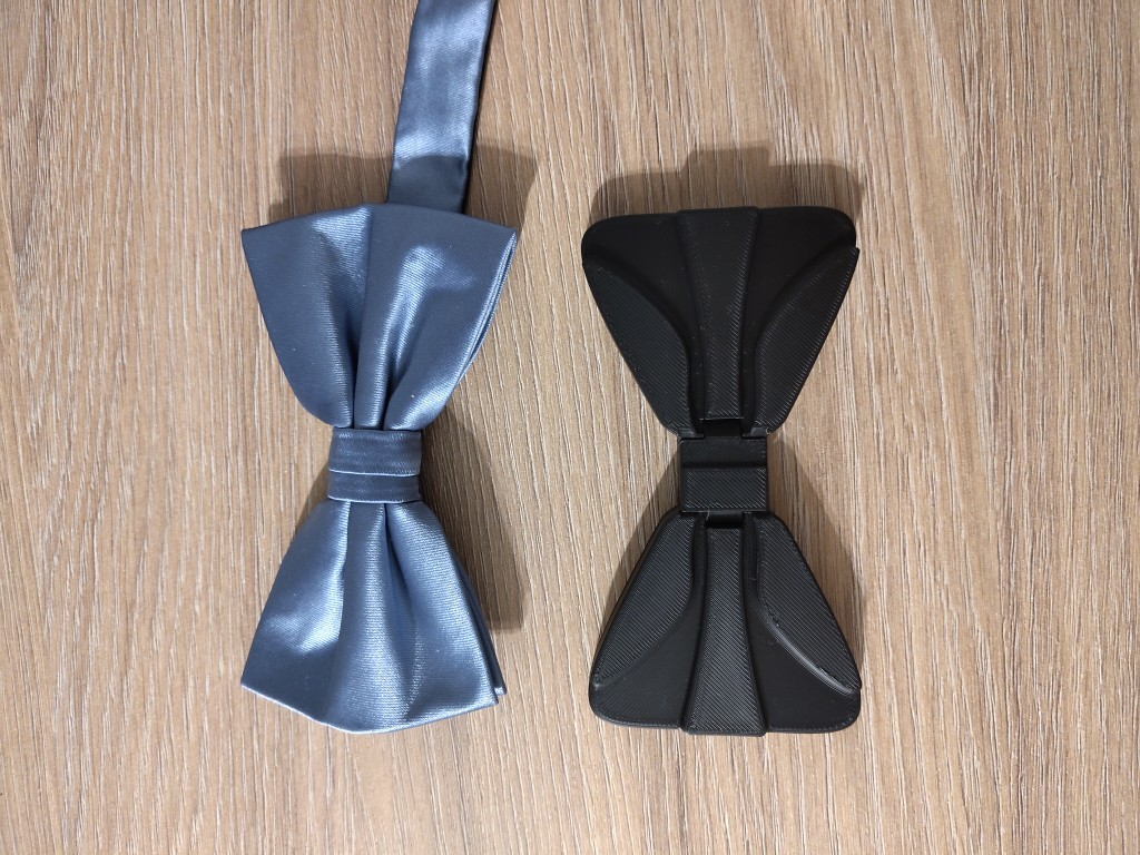
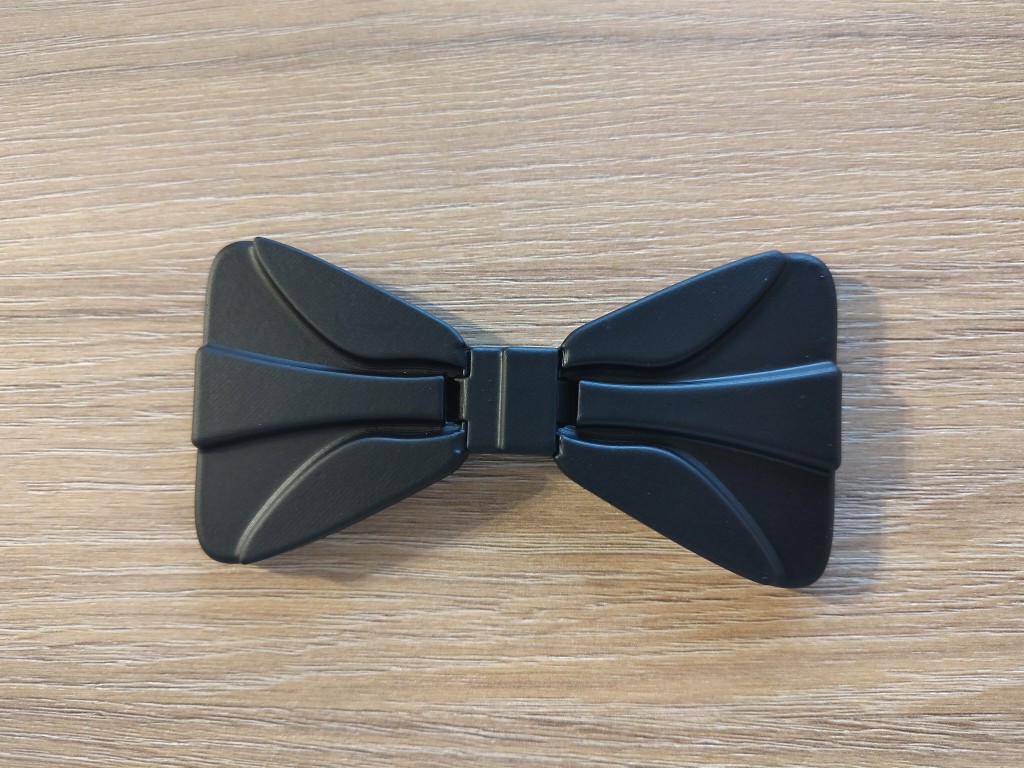
So this week ends without a final popcorn time, but with the picture of a printed bow tie in print-in-place style.
Update from week 06:
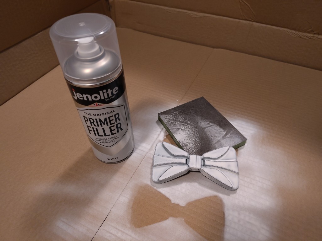
To see what you can get out of a 3D print, I decided to try my hand at post-processing. To do this, I took my bow tie, sanded it and sprayed it with two layers of filler.
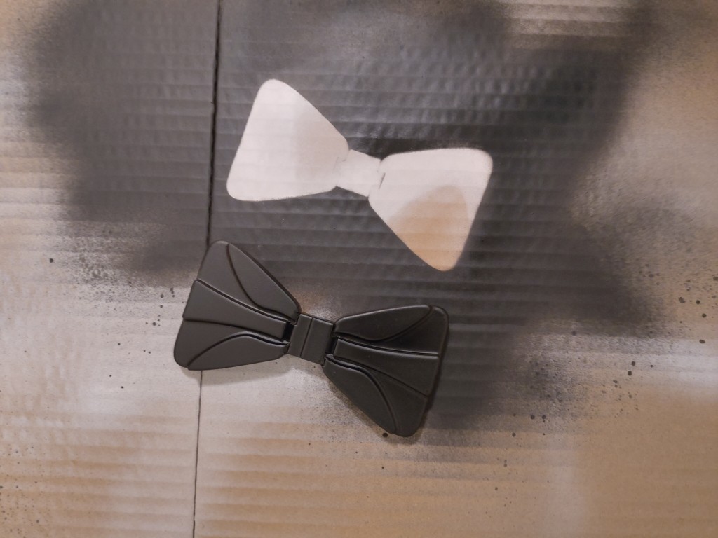
Then I sanded it again and painted it with black spray paint. Can you figure out where the bow tie was when I sprayed it?
After a second coat of paint, the result was as follows, I think it's pretty good. I didn't put too much effort into the post-processing, and the black paint unfortunately didn't spray cleanly either, but sometimes threw out small droplets. What I do think is very important or helpful, however, is the fine sanding sponge used, which adapts well to the geometries of the print. For other geometries, you might not need it so much.