Embedded Programming
This weeks individual assignment:
- Browse through the datasheet for your microcontroller
- Write a program for a microcontroller, and simulate its operation, to interact (with local input &/or output devices) and communicate (with remote wired or wireless connection)
- reflect on your individual page what you learned
This weeks learnings:
This week I discovered that microcontrollers differ more than I would have expected as a layman. If you know what functions you need, it makes sense to be very specific when choosing a microcontroller. At the same time, the programming can be so specific that it may not always be worth learning about it for individual projects.
My microcontroller
As the microcontroller for this week, I chose the ESP32-C3 because of its different functionalities, which I will explain in more detail below. With an eye on the next few weeks,
I have already ordered copies of this in advance, so I was pretty much set for this week.
The ESP32-C3 is particularly suitable for my project because it has extensive wireless connectivity, enough IO pins and predefined energy saving modes. The version offered by Seed Studio
also mentions a LiPo charger. All of this means that the ESP32-C3 is very well suited for mobile and especially communicative applications. It supports both Bluetooth and WiFi, which is
good because I cannot and do not want to decide what I will use in my final project and what I may add to my final project after the FabAcademy. Communication with a smartphone, for example,
is conceivable, but two projects could also communicate with each other at the same time.
Datasheet
Looking at the data sheet is overwhelming at first, if you want to try it yourself, you can do so. That's why I'll just pick individual points from the data sheet here.
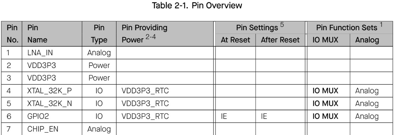
Pin Layout
The pin assignment that I was able to get from the data sheet is shown below. The ESP32-C3 has a total of 32 pins, each with different functions. All pins are divided into three categories: IO pins, analog pins and power pins. Each individual pin is broken down in more detail in the data sheet. I would like to explain just a short excerpt as an example, which follows in the form of a table below the image.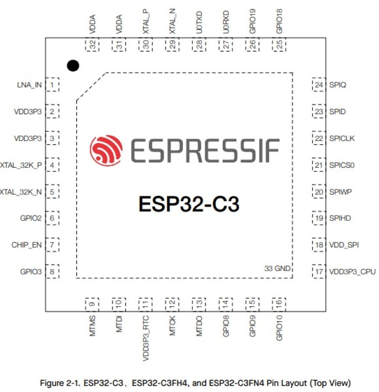
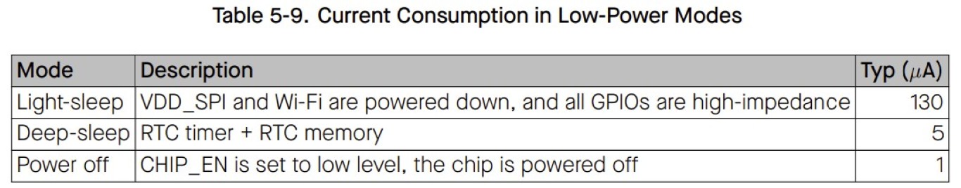
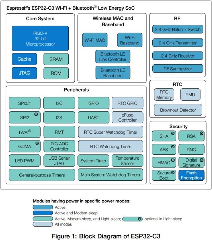
Power Management
Ideally, I will be able to run my final project with batteries. In order to get a little closer to this goal, I obviously have to think about how I can program as energy-efficiently as possible. According to the data sheet, this seems to be complex overall and it is recommended to use fixed modes. According to the data sheet, the following options can be used sensibly. The functionalities that can still be actively used differ depending on the degree of energy saving mode according to the following list.- Active mode: The CPU, RF circuits, and all peripherals are on. The chip can process data, receive, transmit, and listen.
- Modem-sleep mode: The CPU is on, but the clock frequency can be reduced. The wireless connections can be configured to remain active as RF circuits are periodically switched on when required.
- Light-sleep mode: The CPU stops running, and can be optionally powered on. The chip can be woken up via all wake up mechanisms: MAC, RTC timer, or external interrupts. Wireless connections can remain active. Some groups of digital peripherals can be optionally shut down.
- Deep-sleep mode: Only RTC is powered on. Wireless connection data is stored in RTC memory.
Programming and Simulation in Wokwi
Wokwi is a good tool for programming and testing the code in a simulation on the hardware at the same time. I could imagine that the spread of the tool is manageable and
the servers are sized accordingly. Since Neil pointed out this tool to all of us last week, I could imagine that the workload this week is unusually high - so our Bottrop
team unfortunately had frequent overload problems on the server, which is why our projects often couldn't be compiled and simulated. That was definitely frustrating this
week, but I'm confident that that won't be the case if you're reading this and want to work with Wokwi. There is also the option of working locally with VS Studio Code
independently of the servers, but I personally decided against it for time reasons.
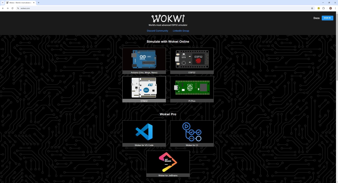
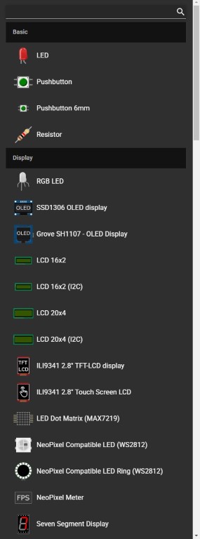
This is what the website looks like. Wokwi offers the option to choose from the microcontrollers displayed, unfortunately all of them cannot be simulated - in my case
with the ESP32-C3 I was lucky.
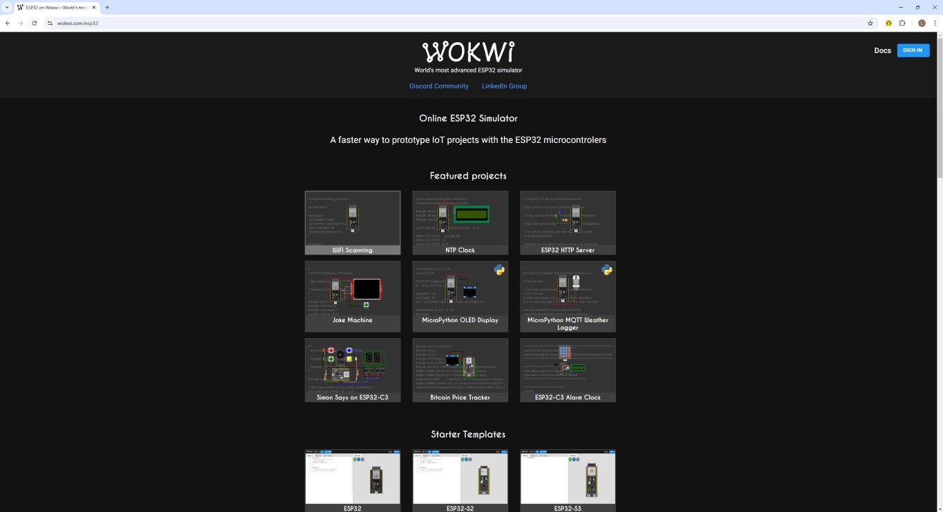
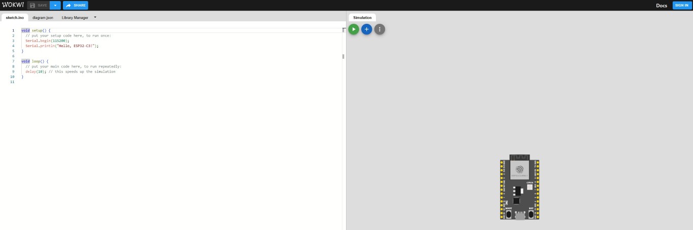
But there are many other examples that you can look at. After looking at some featured projects, I opened a starter template for the ESP32-C3. This will generate the following empty project. The code is on the left, the hardware simulation is on the right.
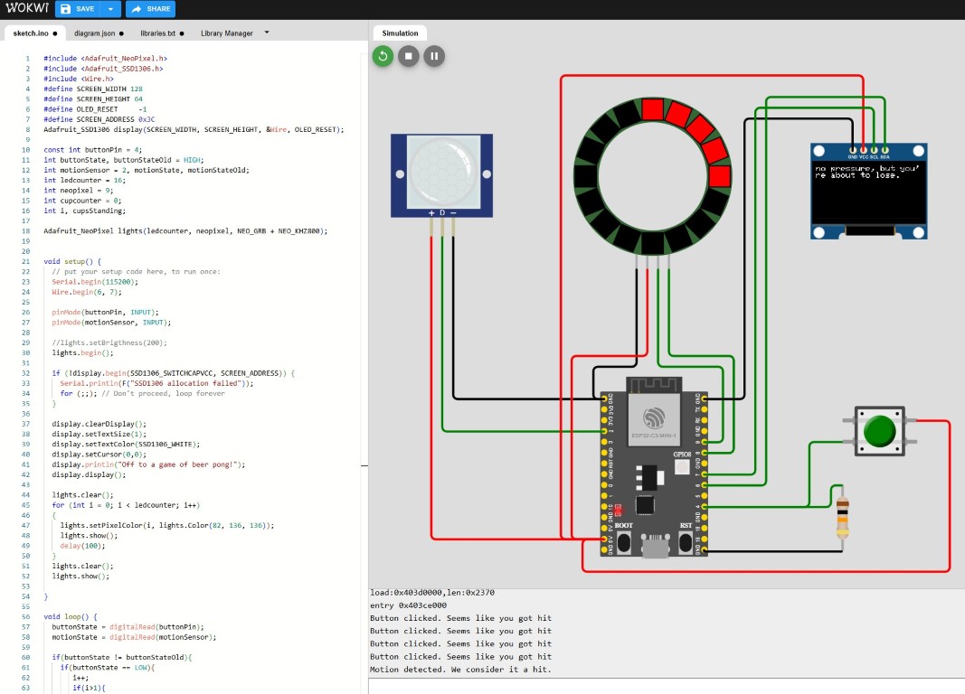
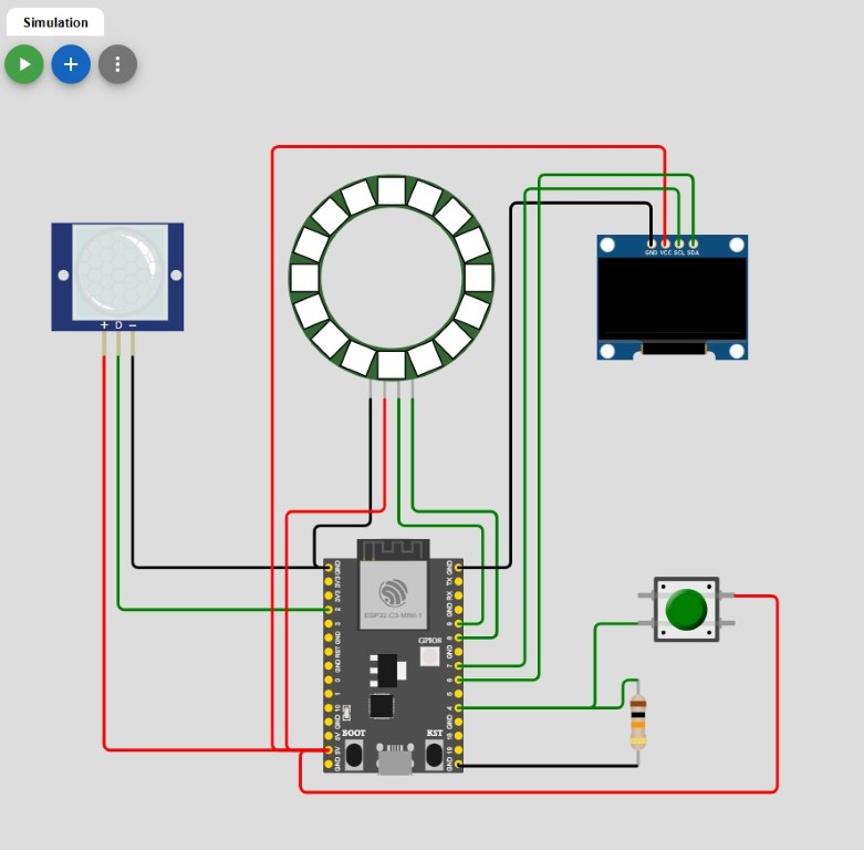
Here you can see my final assembly including wiring. The programming here is in the context of my final project, in which I want to build an interactive area for ten beer pong cups, which is ideally able to recognize hits. I find motivational sayings from sports to be very flat and worn out, but I can laugh very well at demotivation, which is well placed in the context of beer pong. That's why I want to count the cups that are still standing, display or react to the number via LED and output stupid sayings on the screen.
From left to right we see a motion sensor, which in my case is the replacement for hit detection. Next to it is an LED ring of WS2812b LEDs, which will ultimately be a longer LED strip. The display can be seen on the right. Below that is a switch with a pull-up resistor that is supposed to simulate a targeted user input that is supposed to be part of the assignment and that I also symbolize a hit in this simulation.
What I think is great in Wokwi and what you should definitely take with you into real life is the definition of the cable colors. Here you can easily orientate yourself on the standard that red is the power supply, black is ground and green is the data connection. For data connections, however, it is advisable to use other cable colors; at least I would separate data in and data out.
After the hardware, we turn our attention to the software. In the spirit of spiral design, I gradually integrated the code for each individual component and tested the functionality. I can only recommend this approach to everyone, it makes troubleshooting much easier and errors will occur. Here is the code that the project starts with. As you can see from the comments behind the "//"", our program consists of a setup and a loop. The program does nothing more than display "Hello, ESP32-C3!" on the serial monitor.
void setup() {
	// put your setup code here, to run once:
	Serial.begin(115200);
	Serial.println("Hello, ESP32-C3!");
}

void loop() {
	// put your main code here, to run repeatedly:
	delay(10); // this speeds up the simulation
}
void setup() {
	Serial.begin(115200);
	hello_esp();
}

void hello_esp() {
	Serial.println("Hello, ESP32-C3!");
}
const int buttonPin = 4;
int buttonState, buttonStateOld = HIGH;

void setup() {
	pinMode(buttonPin, INPUT);
}

void loop() {
	buttonState = digitalRead(buttonPin);

	if(buttonState != buttonStateOld){
		if(buttonState == LOW){
			hello_esp();
		}

		buttonStateOld = buttonState;
	}

	delay(100);
}
#include "Ardafruit_SSD1306.h"
#include "Wire.h"
#define SCREEN_WIDTH 128
#define SCREEN_HEIGHT 64
#define OLED_RESET -1
#define SCREEN_ADDRESS 0x3C
Adafruit_SSD1306 display(SCREEN_WIDTH, SCREEN_HEIGHT, &Wire, OLED_RESET);

void setup() {
	Wire.begin(6,7);

	if(!display.begin(SSD1306_SWITCHCAPVCC, SCREEN_ADDRESS)) {
		Serial.println(F("SSD1306 allocation failed"));
		for (;;); // Don't proceed, loop forever
	}

	display.clearDisplay();
	display.setTextSize(1);
	display.setTextColor(SSD1306_WHITE);
	display.setCursor(0,0);
	display.println("Hello, ESP32-C3!");
	display.display();
}
int motionSensor = 2, motionState, motionStateOld;

void setup() {
	pinMode(motionSensor, INPUT);
}


void loop() {
	motionState = digitalRead(motionPin);

	if(motionState != motionStateOld){
		if(motionState == HIGH){
			Serial.println("Motion Sensor working. Hello, ESP32-C3!");
		}

		motionStateOld = motionState;
	}

	delay(100);
}
#include "Adafruit_NeoPixel.h"

int ledcounter = 16;
int neopixel = 9;

Adafruit_NeoPixel lights(ledcounter, neopixel, NEO_GRB + NEO_KHZ800);

void setup() {
	lights.begin();

	lights.clear();
	for (int i = 0; i < ledcounter; i++)
	{
	  lights.setPixelColor(i, lights.Color(255, 0, 0));
	  lights.show();
	  delay(500);
	}
	lights.clear();
	lights.show();

}
Next and last, I move from the general operations that are probably best suited for copying to my specific weekly project. The entire code follows, where I'll try to outline the broadest bit without duplicating anything.
initialization and setup()
In the initialization before setup, the only thing that changes is the announcement of the variables cupcounter, cupsStanding and i. Apart from the light color, nothing changes in the setup itself.additional functions
As you can see, I'm not a fan of making the loop() too big, so I outsourced many operations into own functions. In this configuration I have two actions that trigger a hit - the button pressed and the registered movement. On the one hand, I would like to simulate a hit animation, which in this case is defined in the got_hit() function. The LED ring makes two quick rounds in white color.The cup counter is then counted up in the counting_cups() function, which is then passed to the next function and further processed in a switch case.
The function generate_motivation() may not have the most appropriate name, but depending on the number of cups hit, it generates a screen output and ensures that it is displayed. What's important to know is that the screen is visible to the team whose cups decrease when the opponent scores. Accordingly, smaller numbers of remaining cups become increasingly critical. If there are no more cups left and the game is lost, a request for the next game appears as an interim display until counting can begin again. The counter is also finally reset.
Before, the counter is passed on from this function in order to calculate the number of cups that are still standing in the set_lights() function. A red LED is finally switched on for each standing cup.
loop()
As already described, the loop() function is narrow, many parts are already known. The only important thing is the scanning of our detected hits. For debugging I use the serial monitor and corresponding outputs so that in case of doubt I can always use the serial monitor to check whether my program jumps to the right if queries at the right times. During debugging, I noticed that the first if query is always triggered when the program starts and produces the output of the clicked button. That's why I installed an additional counter that intercepts the first jump into this function every time the microcontroller is restarted.That's it for the code, have fun looking through it. To try it out, my entire Wokwi project for this week can be downloaded below. Of course, a blockbuster-like video of the simulation follows in order to have more than this bland and dry functional description of the code.
#include "Adafruit_NeoPixel.h"
#include "Adafruit_SSD1306.h"
#include "Wire.h"
#define SCREEN_WIDTH 128
#define SCREEN_HEIGHT 64
#define OLED_RESET     -1
#define SCREEN_ADDRESS 0x3C
Adafruit_SSD1306 display(SCREEN_WIDTH, SCREEN_HEIGHT, &Wire, OLED_RESET);

const int buttonPin = 4;
int buttonState, buttonStateOld = HIGH;
int motionSensor = 2, motionState, motionStateOld;
int ledcounter = 16;
int neopixel = 9;
int cupcounter = 0;
int i, cupsStanding;

Adafruit_NeoPixel lights(ledcounter, neopixel, NEO_GRB + NEO_KHZ800);


void setup() {
  Serial.begin(115200);
  Wire.begin(6, 7);

  pinMode(buttonPin, INPUT);
  pinMode(motionSensor, INPUT);

  //lights.setBrigthness(200);
  lights.begin();

  if (!display.begin(SSD1306_SWITCHCAPVCC, SCREEN_ADDRESS)) {
    Serial.println(F("SSD1306 allocation failed"));
    for (;;); // Don't proceed, loop forever
  }

  display.clearDisplay();
  display.setTextSize(1);
  display.setTextColor(SSD1306_WHITE);
  display.setCursor(0,0);
  display.println("Off to a game of beer pong!");
  display.display();

  lights.clear();
  for (int i = 0; i < ledcounter; i++)
  {
    lights.setPixelColor(i, lights.Color(82, 136, 136));
    lights.show();
    delay(100);
  }
  lights.clear();
  lights.show();

}

void loop() {
  buttonState = digitalRead(buttonPin);
  motionState = digitalRead(motionSensor);

  if(buttonState != buttonStateOld){
    if(buttonState == LOW){
       i++;
       if(i>1){
       Serial.println("Button clicked. Seems like you got hit");
       got_hit();
       counting_cups();
       }
    }

    buttonStateOld = buttonState;
  }

  if(motionState != motionStateOld){
    if(motionState == HIGH){
      Serial.println("Motion detected. We consider it a hit.");
      got_hit();
      counting_cups();
    }

    motionStateOld = motionState;
  }

  delay(100); // this speeds up the simulation
}

void counting_cups(){
  cupcounter ++;

  generate_motivation(cupcounter);
}

void generate_motivation(int a){
  switch(cupcounter){
    case 1:
      display.clearDisplay();
      display.setCursor(0,0);
      display.println("if this is what the start looks like, I don't want to see the end.");
      display.display();
      set_lights(cupcounter);
      break;
    case 2:
      display.clearDisplay();
      display.setCursor(0,0);
      display.println("it looks like your opponents are starting to warm up. maybe that's not even a good thing.");
      display.display();
      set_lights(cupcounter);
      break;
    case 3:
      display.clearDisplay();
      display.setCursor(0,0);
      display.println("every beginning is difficult, but slowly it becomes uncomfortable.");
      display.display();
      set_lights(cupcounter);
      break;
    case 4:
      display.clearDisplay();
      display.setCursor(0,0);
      display.println("if you keep playing like this, you’ll soon just be drinking out of frustration.");
      display.display();
      set_lights(cupcounter);
      break;
    case 5:
      display.clearDisplay();
      display.setCursor(0,0);
      display.println("no pressure, but you're about to lose.");
      display.display();
      set_lights(cupcounter);
      break;
    case 6:
      display.clearDisplay();
      display.setCursor(0,0);
      display.println("statistically speaking, you now have even fewer chances.");
      display.display();
      set_lights(cupcounter);
      break;
    case 7:
      display.clearDisplay();
      display.setCursor(0,0);
      display.println("maybe throwing isn't your thing... try drinking");
      display.display();
      set_lights(cupcounter);
      break;
    case 8:
      display.clearDisplay();
      display.setCursor(0,0);
      display.println("that doesn’t look good. So for you.");
      display.display();
      set_lights(cupcounter);
      break;
    case 9:
      display.clearDisplay();
      display.setCursor(0,0);
      display.println("diamonds are created under pressure - or sometimes just excuses.");
      display.display();
      set_lights(cupcounter);
      break;
    case 10:
      display.clearDisplay();
      display.setCursor(0,0);
      display.println("what a defeat! sometimes you lose, sometimes the others win. don't get discouraged, it has to work at some point.");
      display.display();
      set_lights(cupcounter);
      break;
    case 11:
      display.clearDisplay();
      display.setCursor(0,0);
      display.println("no problem if you want to get right back to losing - just keep it up! Here comes the next round.");
      display.display();

      cupcounter = 0;
      set_lights(cupcounter);
      break;
  }

}


void got_hit(){
    lights.clear();
  for (int i = 0; i < ledcounter; i++)
  {
    lights.setPixelColor(i, lights.Color(255, 255, 255));
    lights.show();
    delay(10);
  }
  lights.clear();
  lights.show();

  for (int i = 0; i < ledcounter; i++)
  {
    lights.setPixelColor(i, lights.Color(255, 255, 255));
    lights.show();
    delay(10);
  }
  lights.clear();
  lights.show();
  }


void set_lights(int a){
  lights.clear();
  cupsStanding = 10 - cupcounter;

  for (int i = 0; i < cupsStanding; i++)
  {
    lights.setPixelColor(i, lights.Color(255, 0, 0));
    lights.show();
    delay(100);
  }
}
Here you can see the final version of my project for this week. I tried to give an idea of the functionality of my final project with the existing and usable components in Wokwi, but I will definitely have to change a lot of the code and hardware. In particular, I would like to be able to move the programming to Visual Studio Code as well, but unfortunately I wasn't able to do that this week due to other time constraints and unresolvable errors. But now it's popcorn time again, enjoy the simulation and maybe stop every now and then when you need some demotivation.