This week, I explored the process of creating vinyl stickers with the Cricut Maker 3, from designing in the software to the actual cutting,
while learning the importance of settings like cutting depth and mirroring. Additionally, I worked with Fusion360 to create a parametric design
and used a laser cutter to bring it to life, gaining insights into material settings and safety precautions. Despite my ongoing struggle with creativity,
experimenting with different tools and techniques still led to satisfying results.
cutting with a vinyl cutter
My design
One problem this week is my extreme lack of creativity, which is why my design for the vinyl cut is relatively simple. I have many friends
who did not grow up with German as their mother tongue, but learned it. In conversations, you often notice funny things that you probably
wouldn't have noticed otherwise because they have already become so ingrained. In our beautiful and easy-to-learn language, we often express
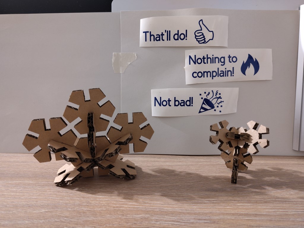
our enthusiasm for successes and successful developments with comments like: "Nicht schlecht", "Kann man so machen" or "Nichts zu meckern".
The British use language in some ways is similar; translated, we say things like "Not bad", "That'll do" or "Nothing to complain!" to express
particular joy. As a little anticipation of our teams feedback in the coming weeks, I took this as an opportunity to work on stickers.
For this I ventured to use the vinyl cutter, which is the Cricut Maker 3 in the FabLab in Bottrop.
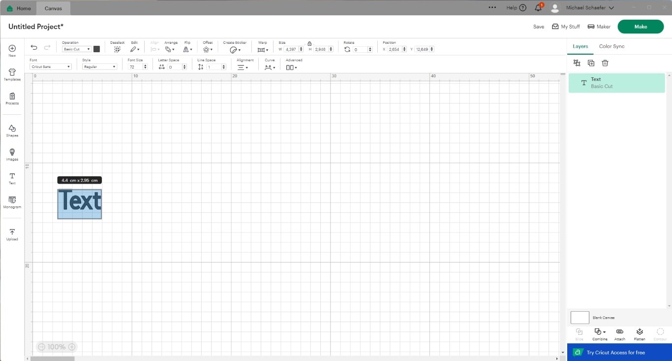
The software to be used for this is that of Cricut itself. This is where you can create the design and also control the machine. After opening
the Cricut software, I created a new project, then an "Untitled Project" was created, which is initially empty. In the following screenshot, I
have already created text from the elements on the left. Here you can enter free text and make further customizations in the menu bar at the top,
in addition to other fonts.
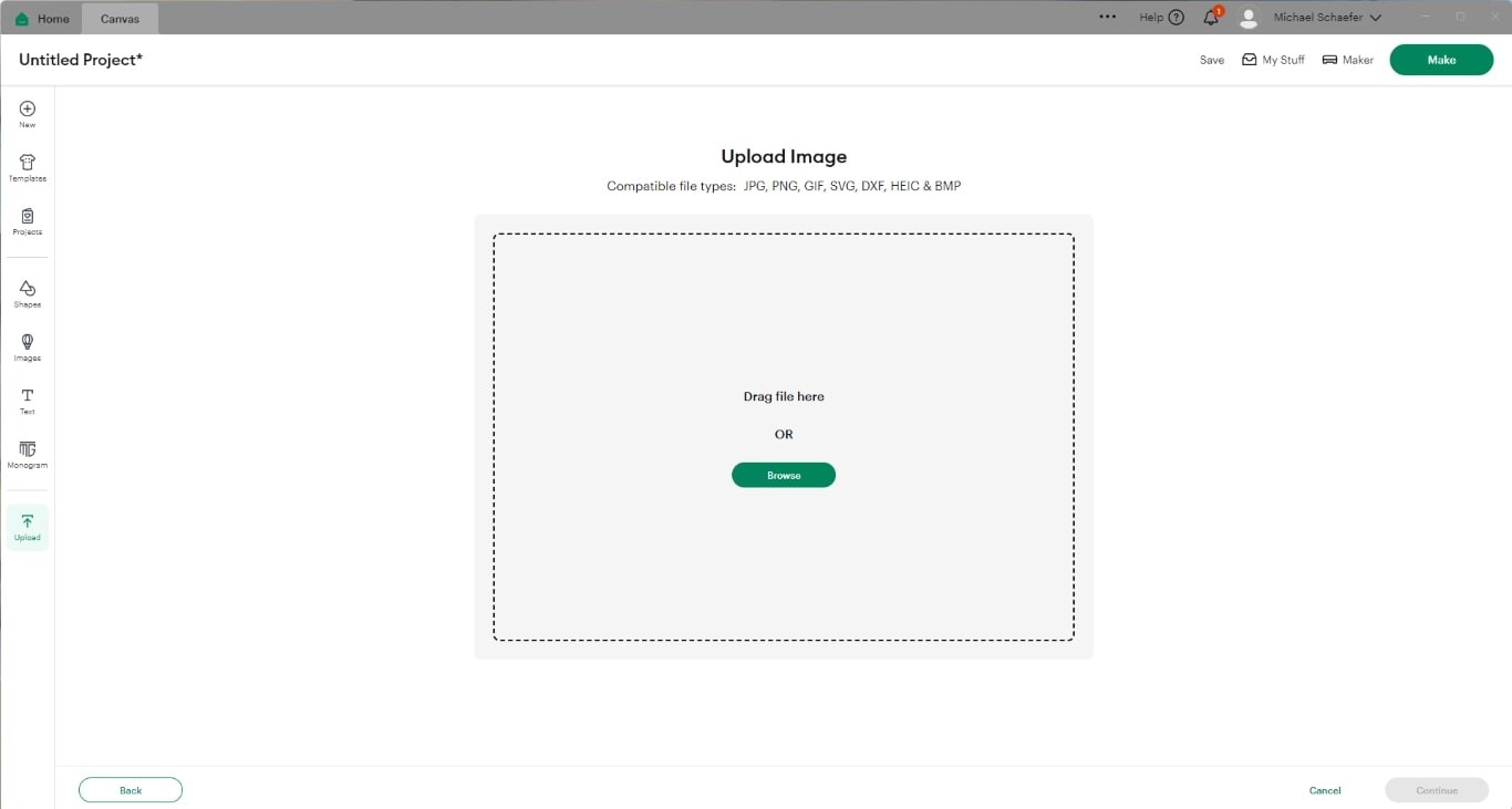
In addition to the font, I need icons to implement my idea, for which I have used existing files from the Internet. This is easily possible using
the Cricut software. At the very bottom of the left bar you will find the "Upload" button. This opens the option to upload files as shown below.
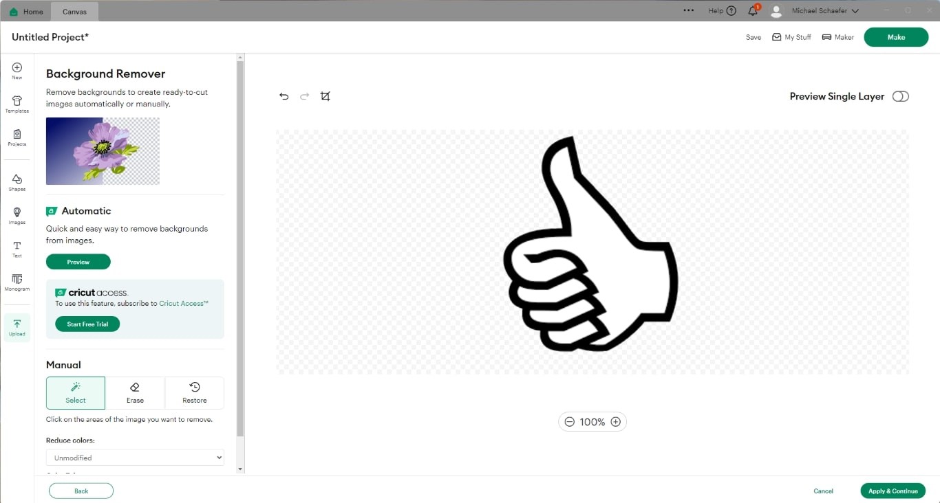
After uploading, a preview image is displayed that corresponds to the image below. You can see that the area outside the icon is shaded with gray
squares. Now it's a matter of removing the background or defining the cutout. The contents of the hand would currently belong to the sticker, only
the outer contour would be cut.
To change this, we use the mouse to select all the non-shaded white areas within the hand. The icon should then look like this, as should any other
image you want to use for vinyl cutting with Cricut.
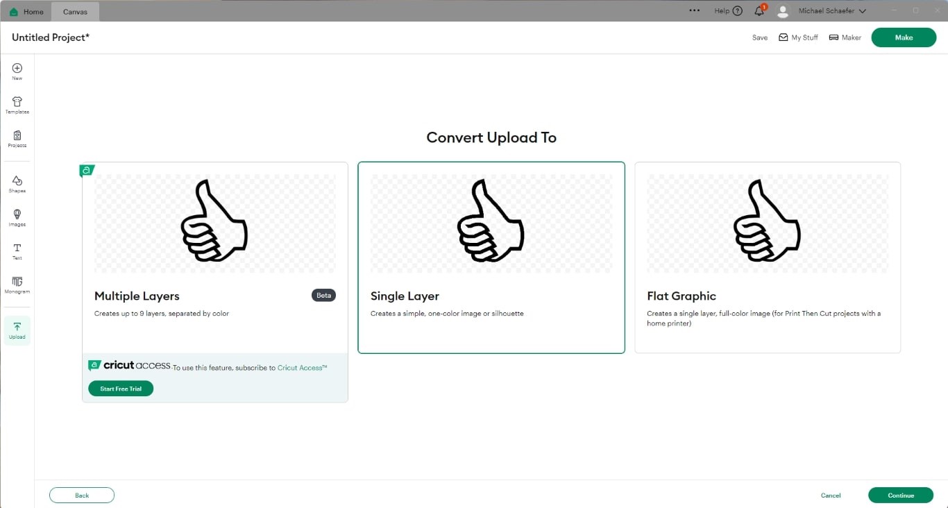
In the next menu we choose Single Layer because our design will be one color. After that another preview image will appear, which we finally confirm
by clicking "Upload" if it is correct.
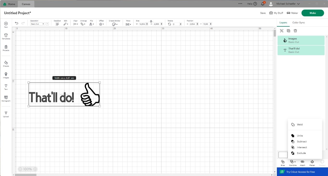
Together with the happy German saying, we have designed a wonderful sticker. Currently, the text and icon are only loosely arranged and would be arranged
freely during the cutting process. To prevent this, we mark both parts and select "Combine" and then "unite" in the bottom right corner. This is how we
have created a sticker from the components. If we want or need to undo this, we can also do this via the field at the bottom right.
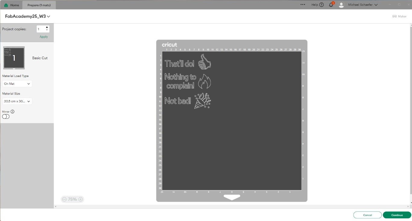
I created the other two stickers in the same way and added them to the workspace. Here you can see the production environment, which you get to when you
click the "Make" button in the top right corner of the design. An important setting to consider in this step is "Mirror". In my case - making stickers -
no mirroring is necessary. The sticker film has an adhesive back and is applied as we see it. With thermal transfer film, i.e. flock or anything that is
applied to textiles, our cut is turned afterwards and the carrier film is on top when ironed on - that's why it's super important to mirror here!! But don't
stress, you're bound to make the mistake at some point.
Clicking "Continue" takes us to the next page where the material is set. For the sticker film that I use, I can choose vinyl as the material from the
predefined selection. The different materials have different cutting depths, so you should give this a little thought. If the cutting depth is not
sufficient, it quickly stops being fun.
Actual cutting
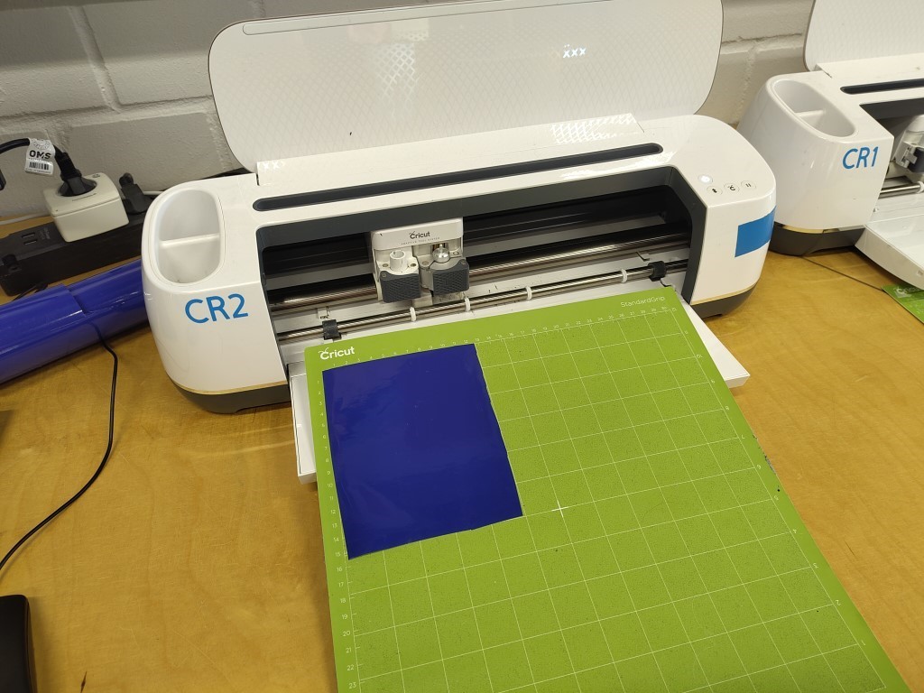
I consider the next step to be part of the actual production process of the stickers. First, sticker film has to be stuck onto the base plate, which corresponds
to the position and size of the cut in the preview above. Next, you can see the two dark gray wheels on the front axle of the machine itself. The base plate including the sticker film has to be handed over to these so that these wheels
can pull it in in the next step.
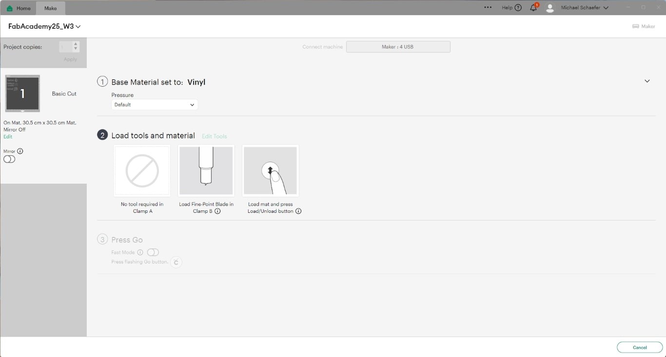
After clicking the "Continue" button at the bottom right of the software, we get to the following menu. I didn't change the contact pressure under point 1, although I probably should have set a higher pressure here. A few individual
cuts didn't go all the way through the sticker film and had to be cut manually afterwards. Now the button shown under point 2 on the machine starts to flash; on the machine it can be found on the right directly under the power button.
After pressing it, the machine loads the mat and the software also jumps to point 3.
Now the button with the Cricut logo on the right next to the loading and unloading lights up on the Cricut Maker 3, which starts the cutting process.
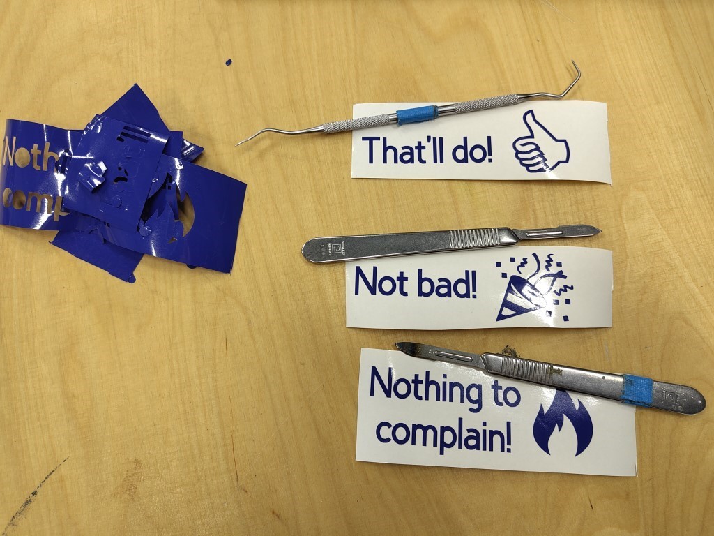
After cutting, we have to unload the mat again and can peel off our sticker film. Finally, we remove all the sticker film that is not part of our design and thus get these wonderful and very German stickers.
Given the final result, in my opinion there is nothing to complain about. Except maybe the slightly dirty table, but that'll do.
Parametric construction kit
My design
Because I'm already familiar with Fusion360 and Inkscape hasn't won my affection yet, I decided to create the parametric design with Fusion.
Once again this week, my lack of creativity has struck. I would have liked to do something useful, but I didn't have any ideas that could be implemented under the given requirements. To avoid producing waste, I used a broken moving
box that I still had as material. My design is inspired by various other years and is very simple. I decided to create a hexagon with six different plug-in options so that you could build different things with it.
If you, like me, are new to parametric design with Fusion360, I can highly recommend the following tutorial from Prusa.
Funnily enough, Autodesk itself also links to this tutorial. In 12 minutes, you'll learn everything you need to know.
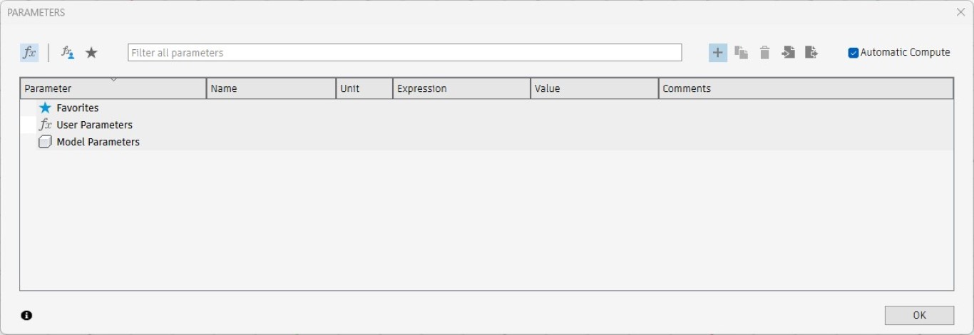
First of all, we start by creating parameters for a new document in Fusion so that we can reference them later in the sketch. We do this by clicking on the Modify > Change Parameters button. This opens the following menu, in which
we can add new parameters using the plus symbol in the top right.
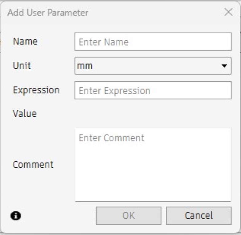
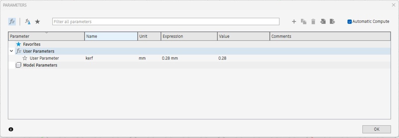
The following window opens to create each new parameter.
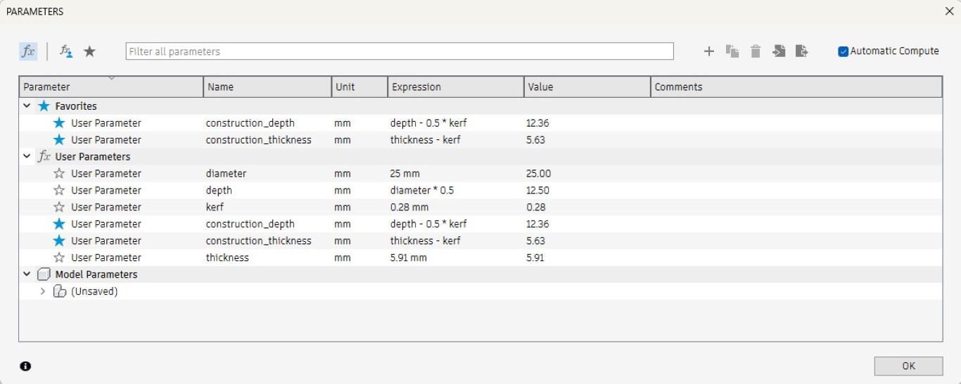
I have created the Kerf here as an example. This way the parameters are still manageable. The following image already contains all the parameters, some of which are calculated from the entered data.
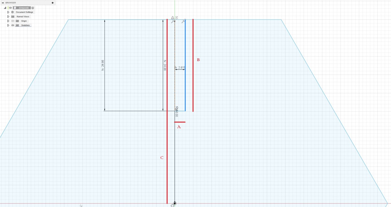
After all the parameters were set, I started with the design. After creating a new sketch, I created a polygon with six corners under Create > Polygon > Circumscribed Polygon. The radius is also requested, which I incorrectly set
as the diameter in the parameters in the retrospective (C). The image already zooms in heavily on the upper half of the hexagon to illustrate the subsequent design. I started with a construction line that runs from the middle of
the hexagon's outer line to the center and whose length corresponds to the construction_depth variable. I set the construction_depth relatively arbitrarily with half the radius, but half a kerf has to be subtracted from this, since
one cut and thus half a cutting width is in the depth. From this point, I went to the right by constructing half the construction_thickness in each case. The construction_thickness is calculated as the material thickness minus the
kerf, because two cuts and thus the full cutting width are made here (A). From there, analogous to the procedure for the construction line, I used a real line to go up again by the construction_depth to connect to the hexagon (B).
The fx in front of the dimension indicates in Fusion that these are calculated values. I mirrored the two lines A and B on the construction line and followed the same pattern for all sides of the hexagon.
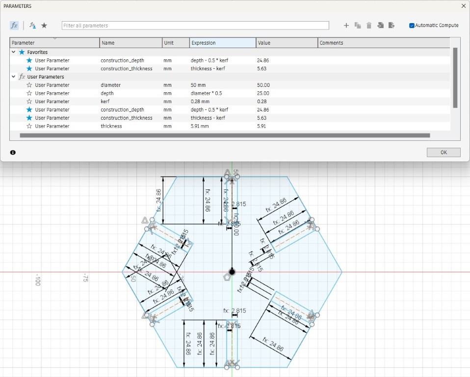
The full sketch including the parameter table then looks like this.
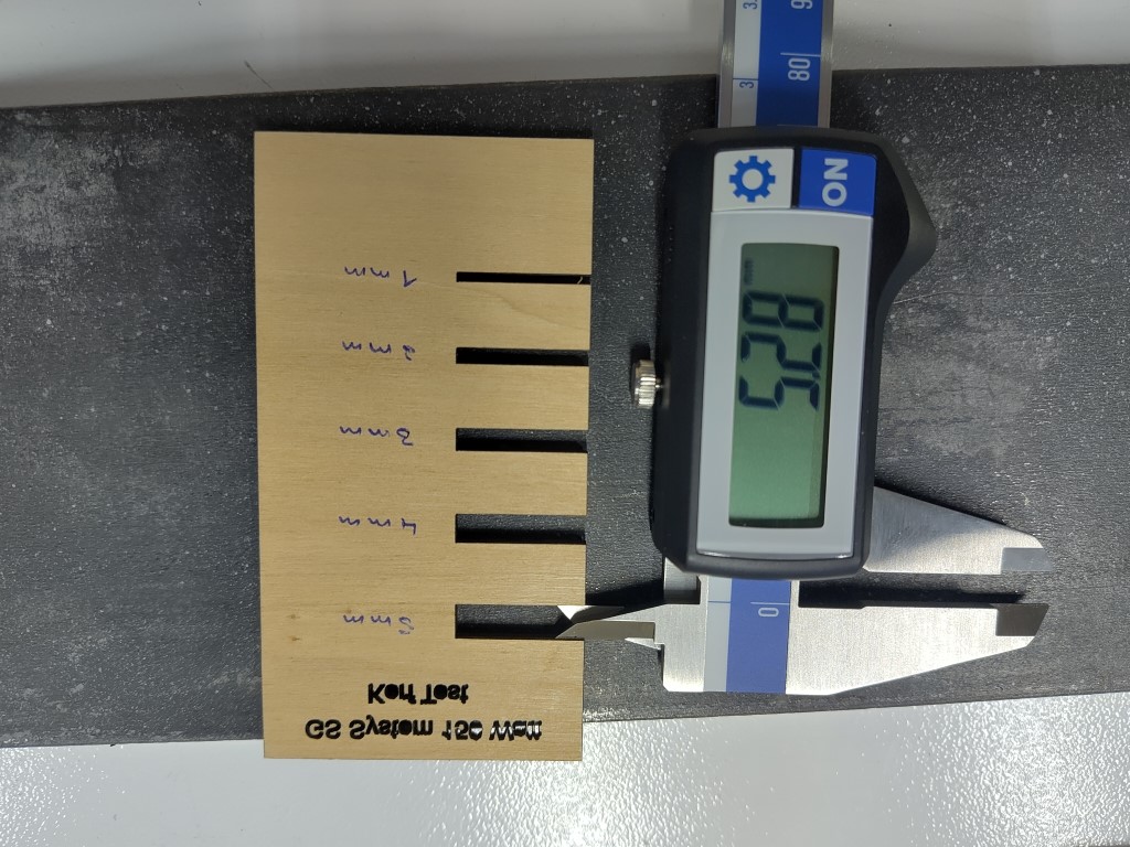
Here you can see my parametric design in action. Kerf is used to set the cutting width of the laser, which in my case comes from the Kerf test of the group assignment. The material thickness can also vary and should be measured
precisely in each case; I would not trust the measurement given when purchasing. By entering these two parameters and the diameter on which the hexagon is based, this design is completely variable. Now that I can see this from a
distance, I notice that the parameter called diameter should actually be called radius. Then it would correspond to what it triggers in reality.
Actual cutting
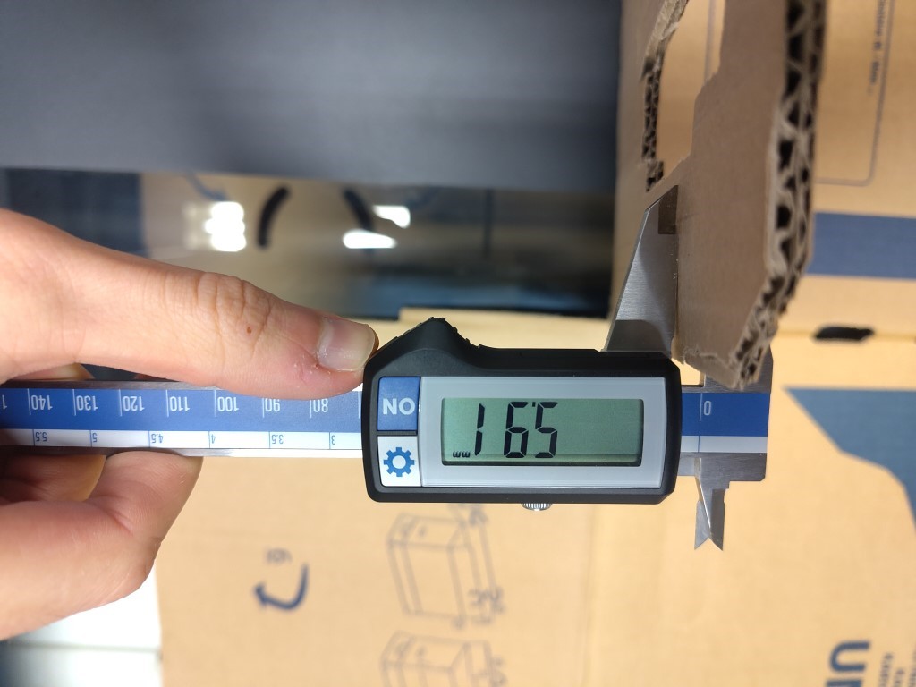
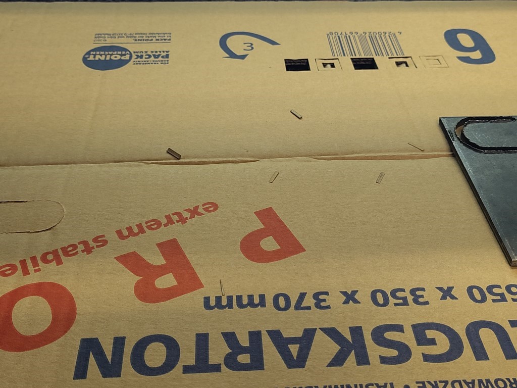
After completing the parametric design in Fusion360, I set the appropriate parameters for my material and the laser cutter. As you can see from the pictures, the cardboard of my moving box was 5.91 mm thick, and the kerf was 0.28 mm,
as previously determined.
I generated a .dxf file for both a 30 mm and a 50 mm diameter by right-clicking on my sketch, which I could use for the laser cutter. The transfer to the laser cutter was done via the
RDWorks software, which is freely available.
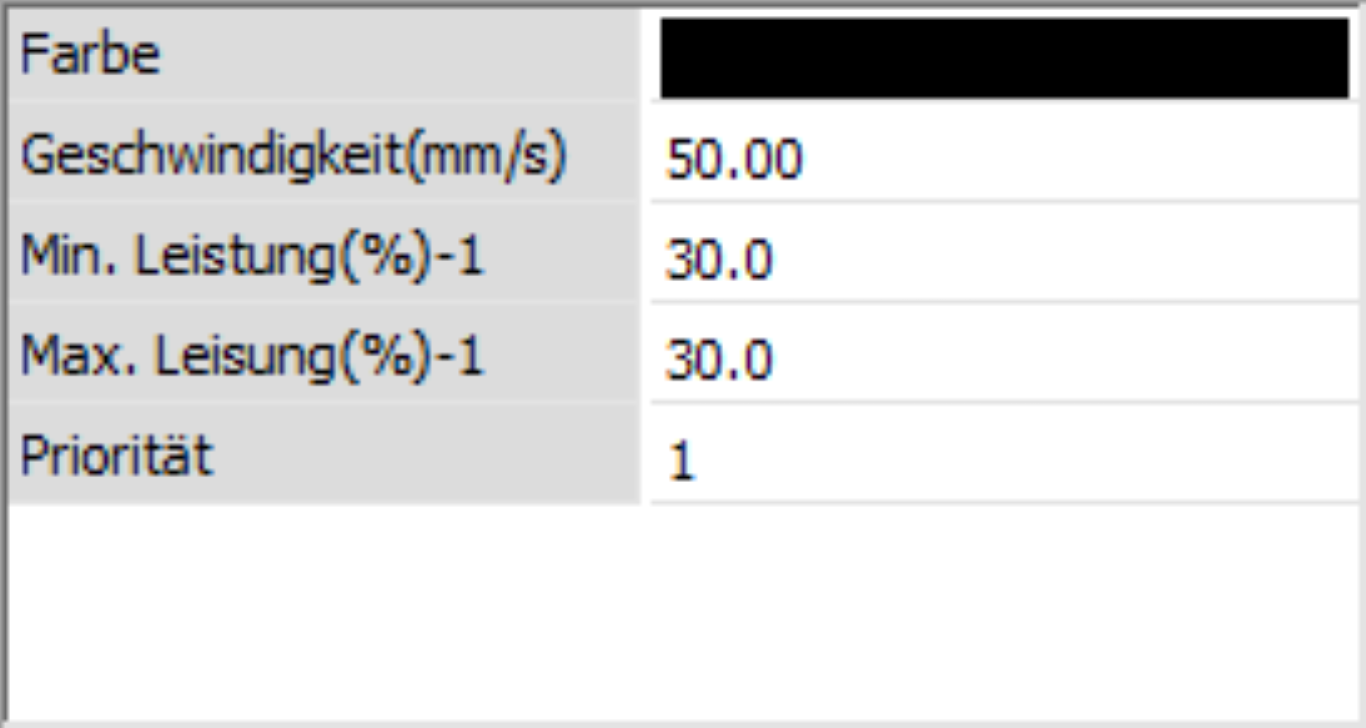
By test cutting small squares, I found that I can cut the cardboard well if I run the laser over
it twice at 50 mm/s speed and 30% power. Because of the fire hazard with cardboard, I didn't want to increase the power or reduce the speed, so it was a good compromise for me to run the laser twice.
Because the software was in German, here is a short translation: The color is shown in line one. This is followed by speed, minimum power, maximum power and priority.
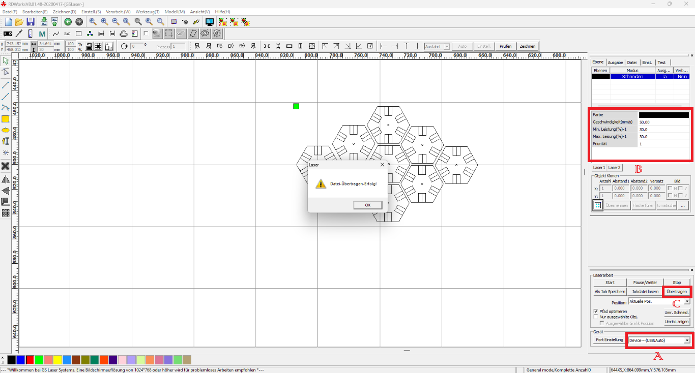
Here you can see my final order for the laser cutter in RDWorks. Starting with importing my .dxf file from Fusion360, I copied the simple design several times using the keyboard shortcut CTRL+C and CTRL+V and arranged
it as shown. At the bottom right you can see that the laser cutter and the PC from which I sent the order were connected via USB (A). After setting the cutting parameters as above (B), I sent the job by clicking on "Übertragen" (C).
That's why the message "Datei-Übertragen-Erfolg!" is displayed in the middle of the screen, which means that the file transfer was successful.
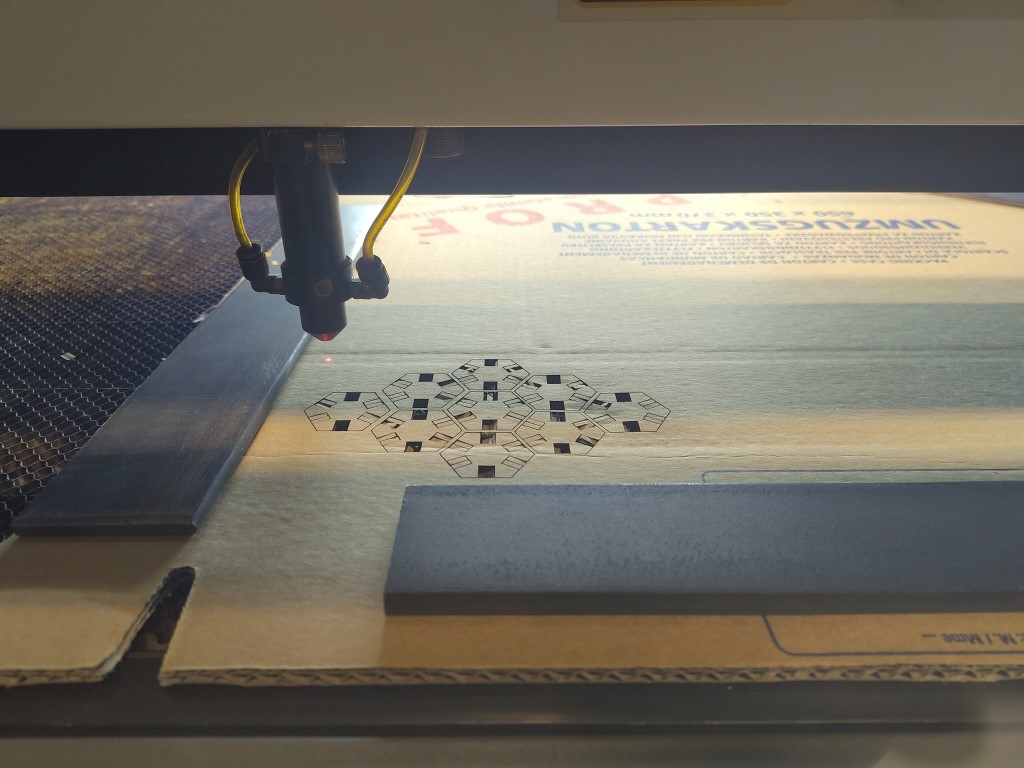
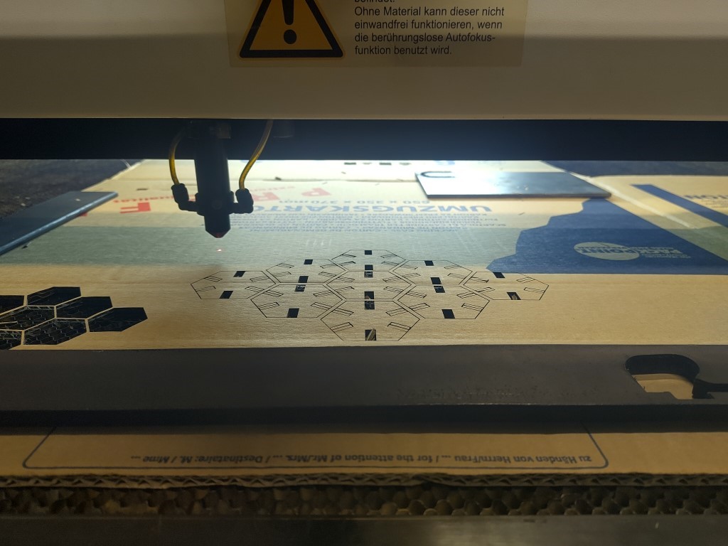
I then loaded the material into the laser cutter itself, activated the autofocus and set an origin. I was then able to safely start the job and make the following cut.
I carried out the second job in a similar way.
When the cardboard is cut, especially if you cut twice like I did, the compressed air causes small pieces to quickly whirl through the laser cutter. Due to the fire hazard posed by these particles, it is in your own interest to vacuum
the construction area thoroughly after production. Hopefully you can see what I mean in the picture. The same particles also land between the honeycombs of the grid or at the bottom of the laser.
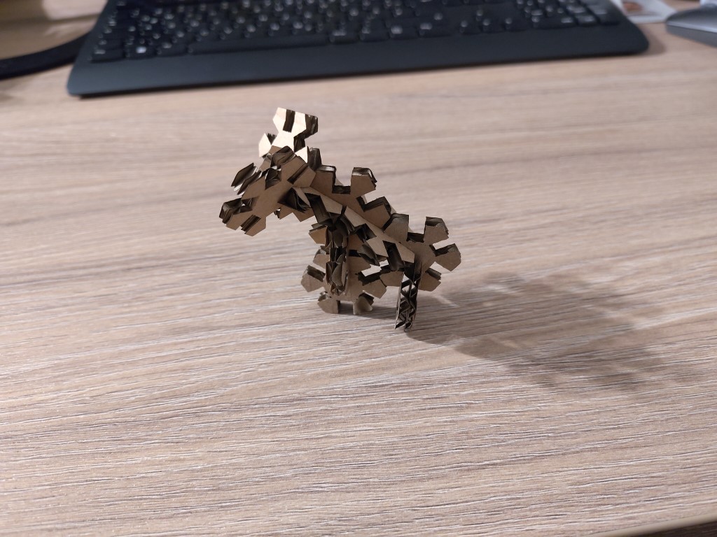
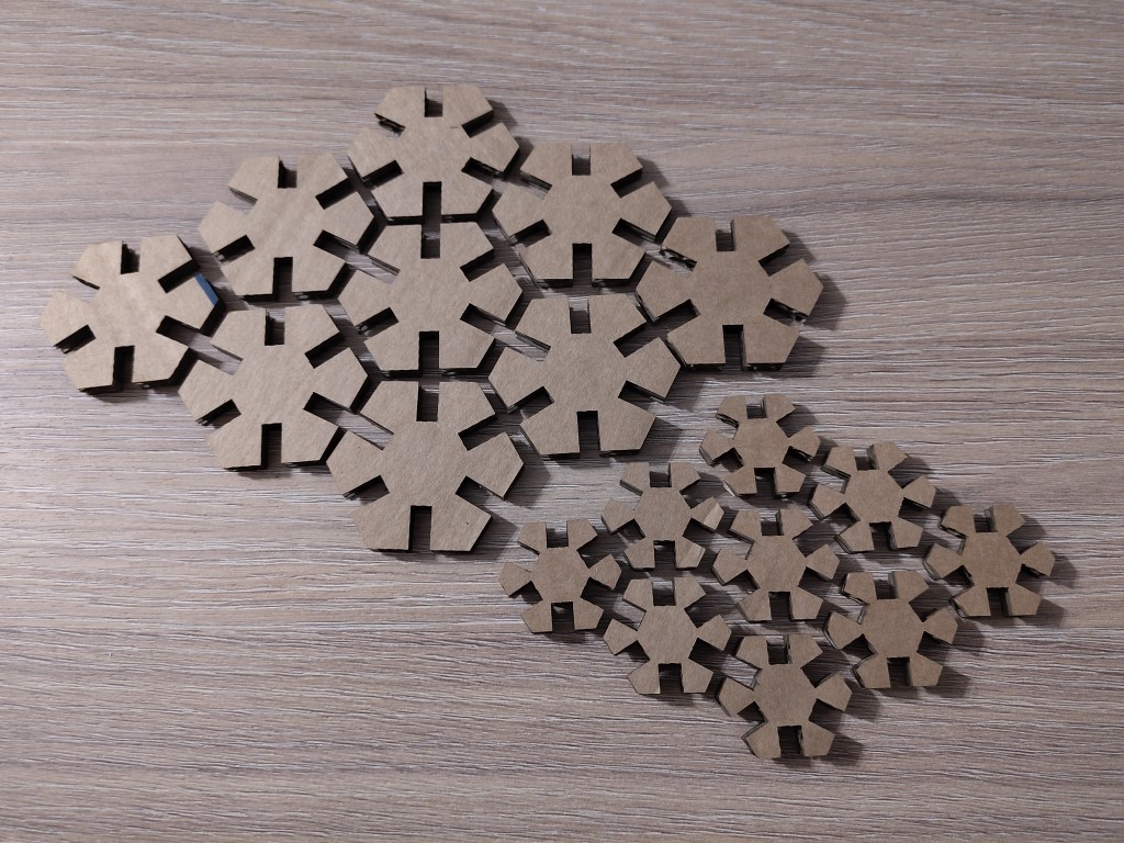
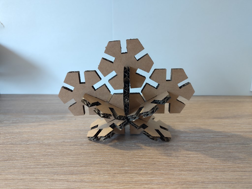
The result is sections of my parametric design, which I then used to express my lack of creativity. The following three images emerged.
That brings me to my hero shot for this week. Thank you for your time.